Table of Contents
Advertisement
Quick Links
Advertisement
Table of Contents

Subscribe to Our Youtube Channel
Related Manuals for Dynojet 250


Summary of Contents for Dynojet 250
- Page 2 ©2014-2018 Dynojet Research, Inc. All Rights Reserved. Upgrade Model 200/250 Dynamometer to DynoWare RT Installation Guide This manual is copyrighted by Dynojet Research, Inc., hereafter referred to as Dynojet, and all rights are reserved. This manual, as well as the software described in it, is furnished under license and may only be used or copied in accordance with the terms of such license.
-
Page 3: Table Of Contents
..........2-14 Upgrade Model 200/250 Dynamometer to DynoWare RT Installation Guide... - Page 4 ............Index-i Upgrade Model 200/250 Dynamometer to DynoWare RT Installation Guide...
-
Page 5: Warnings
Dynojet reserves the right to revise this publication and to make changes from time to time in the content hereof without obligation of Dynojet to notify any person of such revision or changes. - Page 6 To avoid ESD damage, always practice good ESD control precautions when servicing the dynamometer. Dynojet designs its dynamometers to be very tolerant of static shocks by the users, but the electronics are vulnerable when the electronics are exposed.
- Page 7 Do not repair or replace any part of the dynamometer or attempt any servicing unless specifically recommended in published user-repair instructions that you understand and have the skills to carry out. Version 7 Upgrade Model 200/250 Dynamometer to DynoWare RT Installation Guide...
- Page 9 200/250 RT U ODEL PGRADE Thank you for purchasing the DynoWare RT upgrade for your Dynojet dynamometer. This upgrade gives you the latest Dynojet dynamometer electronics, the latest software, and future upgrades to the software giving you the power to get the maximum performance out of vehicles you evaluate.
-
Page 10: Introduction
C H A P T E R 1 Introduction INTRODUCTION Before installing the DynoWare RT electronics on your Dynojet dyno, please take a moment to read this guide for installation instructions, features, and other important information. ONVENTIONS ANUAL The conventions used in this manual are designed to protect both the user and the equipment. -
Page 11: Dynoware Rt Electronics
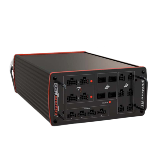
DynoWare RT electronics can be found in the Power Core help. DynoWare RT eddy current main module brake driver air fuel ratio module speed pickup Figure 1-1: DynoWare RT Electronics Version 7 Upgrade Model 200/250 Dynamometer to DynoWare RT Installation Guide... - Page 12 Do not press this button unless drum 2 speed inputs and Instructions instructed to do so by a Dynojet digital brake outputs. technician. This button may need to be pressed to update the device. Upgrade Model 200/250 Dynamometer to DynoWare RT Installation Guide...
-
Page 13: Network Connections
ETWORK ONNECTIONS The Dynojet DynoWare RT dyno electronics connects to your computer directly or over a Local Area Network. If you have an existing network, connect the DynoWare RT main module to a router or a network switch on your network. If you do not have an existing network, you can create a network for the DynoWare RT by connecting the main module to a router. -
Page 14: Unpacking The Dynoware Rt Parts
network cable P/N 42900000 pickup (2) P/N 76950203 connector cable, pickup/brake P/N 44329902 P/N 76950548 socket (2) cable, IR temp sensor P/N 44359120 P/N 76950628 *model 250 dynos only Upgrade Model 200/250 Dynamometer to DynoWare RT Installation Guide... -
Page 15: Unpacking The Dynoware Rt Parts
CAN control adapter P/N 66400019 P/N 76950807 *model 250 dynos only speed pickup screw, mach 8-32 x 1/2" (2) P/N 68300002 P/N 8-32 X .5 SCREW pendant assembly P/N 76100007 Version 7 Upgrade Model 200/250 Dynamometer to DynoWare RT Installation Guide... -
Page 16: Remove The Dynoware Ex Electronics
Remove the four bolts securing the eddy current brake cover and set aside. Remove the 3/8-inch bolts and clamps. eddy current brake cover clamp MC0006 Figure 1-3: Remove the Eddy Current Brake Cover Upgrade Model 200/250 Dynamometer to DynoWare RT Installation Guide... - Page 17 Remove the four bolts securing the hood to the dyno and set aside. Prop up the hood. If present, disconnect the wires to the key switch. Remove the hood from the dyno and set aside MC0007 key switch Figure 1-4: Remove the Hood Version 7 Upgrade Model 200/250 Dynamometer to DynoWare RT Installation Guide...
- Page 18 10 Remove the four screws securing the theta controller and remove the theta controller and bumpers. Set aside the screws and bumpers. theta controller EB014 Figure 1-6: Removing the Theta Controller Upgrade Model 200/250 Dynamometer to DynoWare RT Installation Guide 1-10...
- Page 19 11 Remove the two screws securing the pickup card. 12 Remove the pickup card and pickup card cable. 13 Remove the 25-pin communication cable. pickup card MC136 Figure 1-7: Removing the Pickup Card Version 7 Upgrade Model 200/250 Dynamometer to DynoWare RT Installation Guide 1-11...
-
Page 20: Dynoware Rt Installation
ICKUP ISK AND ICKUP The existing pickup disk will remain installed on the dyno for both model 200 and 250 installations. Install the speed pickup disk on the drum shaft. • Model 200 dynos—Model 200 dynos will use the existing pickup disk with the new speed pickup card. - Page 21 Secure the pickup card to the dyno using two 8-32 x 1/2-inch screws and two #10 flat washers. pickup card pickup card model 200 dynos model 250 dynos Figure 1-9: Securing the Pickup Card Version 7 Upgrade Model 200/250 Dynamometer to DynoWare RT Installation Guide 1-13...
- Page 22 Tighten the pickup disk screws and the pickup card mounting screws. Note: For model 250 dynos, bend the old pickup disk to the side to clear the new pickup card. pickup disk...
-
Page 23: Installing The Eddy Current Brake Driver
NSTALLING THE URRENT RAKE RIVER Use the following instructions if your dyno (model 250) is equipped with an eddy current brake. Secure each mounting bracket (P/N 21200068) to the eddy current brake driver using two 4-40 x 1/4-inch screws each. -
Page 24: Verifying The Eddy Current Brake Wiring Configuration
Connect the other 240VAC leg to the white wire in the existing cable. Connect the ground conductor to the green wire in the existing cable. Alternatively, you can order the Dynojet plug and socket set P/N 78100034 (European P/N 78100035) and use the instructions in... -
Page 25: Cable Routing
Dynojet Powersports products to the DynoWare RT (PCV, OBD2) I - 76950791 CAN control cable, 15' connects the eddy current brake driver to the DynoWare RT using the CAN adapter cable Version 7 Upgrade Model 200/250 Dynamometer to DynoWare RT Installation Guide 1-17... -
Page 26: Routing The Cables
Attach the 2-pin connector from the pickup/brake cable (E) to the brake solenoid leads. Note: The white two-pin connector on the speed pickup/brake cable is only used if an air brake is installed. Upgrade Model 200/250 Dynamometer to DynoWare RT Installation Guide 1-18... - Page 27 18b Insert the PCV CAN termination plug (N) in the PCV module. Note: If you are not using a PCV, be sure to save the PCV CAN termination plug (N) for future use. Version 7 Upgrade Model 200/250 Dynamometer to DynoWare RT Installation Guide 1-19...
- Page 28 C H A P T E R 1 Cable Routing Figure 1-15: Routing the Cables Upgrade Model 200/250 Dynamometer to DynoWare RT Installation Guide 1-20...
-
Page 29: Testing
Figure 1-16: Use the Pendant to Release the Brake Spin the drum. Look for the LED on the pickup card to flash. LED light on pickup card Figure 1-17: Pickup Card LED Light Apply the brake. Version 7 Upgrade Model 200/250 Dynamometer to DynoWare RT Installation Guide 1-21... -
Page 30: Replace The Covers
If present, connect the wires to the key switch. Lower the hood and secure to the dyno using the four bolts removed earlier. MC0007 key switch Figure 1-18: Replacing the Hood Upgrade Model 200/250 Dynamometer to DynoWare RT Installation Guide 1-22... - Page 31 Secure the clamps using the 3/8-inch bolts removed earlier. Secure the eddy current brake cover using the four bolts removed earlier. eddy current brake cover clamp MC0006 Figure 1-19: Replacing the Eddy Current Brake Cover Version 7 Upgrade Model 200/250 Dynamometer to DynoWare RT Installation Guide 1-23...
- Page 33 • Grounding the Vehicle, page 2-9 • Pre-Run Inspection, page 2-10 • Using the Starter, page 2-12 • Using the Dyno, page 2-12 • Making a Test Run, page 2-13 • Preventative Maintenance, page 2-14 Upgrade Model 200/250 Dynamometer to DynoWare RT Installation Guide...
-
Page 34: Loading The Bike
With the motorcycle in neutral, align the wheel in the center of the knurl by pressing the dyno starter switch. tire stop tire strap center drive axle on dyno drum adjust carriage to align rear axle with drum Figure 2-1: Align the Wheel and Axle Upgrade Model 200/250 Dynamometer to DynoWare RT Installation Guide... - Page 35 Never perform a dyno run if the tie-down straps are not in place or they are damaged. tie-down strap tie-down location Figure 2-2: Attach the Tie-down Straps Version 7 Upgrade Model 200/250 Dynamometer to DynoWare RT Installation Guide...
-
Page 36: Connecting The Rpm Pickup
Connecting the RPM Pickup CONNECTING THE RPM PICKUP Your Dynojet dynamometer includes two primary wire inductive pickups and two secondary wire inductive pickups. These small “clothespin like” inductive pickups are used to sense RPM. An RPM pickup is required if you want to view torque graphs. -
Page 37: Connecting The Primary Inductive Pickup
Refer to “Grounding the Vehicle” on page 2-9. connect the primary pickup opposite the battery source ignition box primary secondary coil from battery source Figure 2-3: Tachometer Pickup Primary Inductive Version 7 Upgrade Model 200/250 Dynamometer to DynoWare RT Installation Guide... - Page 38 Pink Ducati Gray or Green/Brown Green or Violet/Yellow Harley Blue or Pink Honda Yellow or Yellow/Blue Kawasaki Green Suzuki White or Black/Blue Triumph Brown/Yellow Yellow/Blue Green/Black Black/Green Yamaha Orange or Gray Upgrade Model 200/250 Dynamometer to DynoWare RT Installation Guide...
-
Page 39: Connecting The Secondary Inductive Pickup
Note: When using one secondary pickup, disconnect the other pickup from the dyno electronics. connect a secondary pickup to an available ignition box spark plug wire primary secondary Secondary Coil from battery source Figure 2-4: Tachometer Pickup Secondary Inductive Version 7 Upgrade Model 200/250 Dynamometer to DynoWare RT Installation Guide... - Page 40 • Using a jumper wire, ground the metal case of the inductive clip to the motorcycle chassis. • Rout the inductive wire(s) 90 degrees (perpendicular) away from the motorcycle. When laid alongside (parallel) to the motorcycle they can act as an antenna. Upgrade Model 200/250 Dynamometer to DynoWare RT Installation Guide...
-
Page 41: Grounding The Vehicle
Secure the grounding bracket to this location using one 1/4-20 x 1/2-inch screw. Attach the vehicle ground cable to an exhaust bolt or engine bolt on the vehicle. Attach the vehicle ground cable to the grounding bracket. Version 7 Upgrade Model 200/250 Dynamometer to DynoWare RT Installation Guide... -
Page 42: Pre-Run Inspection
Never allow any person(s) to stand behind the dyno or vehicle when it is being operated. Only the operator should be near the dyno or the vehicle during the test. Upgrade Model 200/250 Dynamometer to DynoWare RT Installation Guide 2-10... -
Page 43: Before Starting The Engine
• Fix any fuel, oil, or coolant leaks that may have shown up after engine warm up and check the carburetor for leaks. • Any loud or unusual engine noises or excessive exhaust smoke should be resolved before continuing. Version 7 Upgrade Model 200/250 Dynamometer to DynoWare RT Installation Guide 2-11... -
Page 44: Using The Starter
With the bike properly loaded and secured, you are now ready to begin making runs and using your dyno. From here you will need to refer to the Power Core Help for detailed information on using the Power Core suite of applications. Upgrade Model 200/250 Dynamometer to DynoWare RT Installation Guide 2-12... -
Page 45: Making A Test Run
Press the red brake button to apply 100% braking and slow down the vehicle. Using the vehicle’s own brakes to slow or stop the drum at speeds over 30 m.p.h. can severely overheat the brake parts. Dynojet dynamometers with the air brake or eddy current brake accessory can be used to slow the vehicle and drum to a full stop at any speed. -
Page 46: Preventative Maintenance
C H A P T E R 2 Preventative Maintenance PREVENTATIVE MAINTENANCE To maintain proper dynamometer operation, Dynojet recommends you make routine checks of the dyno. • Drum—keep the drum clean and keep all objects clear of the drum. • Brake Pads—check the brake pad clearance regularly. Change the brake pads when they are worn to less than 0.060 inch thick. -
Page 47: Appendix A Power Requirements And Installation
This Appendix is divided into the following categories: • North America, Japan, and Locations Using 60 Hz Power, on page A-2 • Excluding North America and Japan, on page A-5 Upgrade Model 200/250 Dynamometer to DynoWare RT Installation Guide... -
Page 48: North America, Japan, And Locations Using 60 Hz Power
UL and NEC safety standards. Note: If you are installing your dyno in North American or Japan and the dyno is not equipped with twist lock four wire grounded plug, contact Dynojet before attempting to connect the dyno. -
Page 49: Testing For Correct Voltages
You must have a licensed electrician correct the power connection. Connecting the dyno to the incorrect voltage can result in damage to the dyno and will void the dyno warranty. Contact Dynojet with any questions. Using a voltmeter that is capable of measuring AC voltage, measure between the points listed below and verify that the correct voltages are present. -
Page 50: Hard Wiring To The Building
Refer to the previous table for testing and probe the new connections as follows: • white wire as location #2 • black wire as location #4 • green wire as location #3 Upgrade Model 200/250 Dynamometer to DynoWare RT Installation Guide... -
Page 51: Excluding North America And Japan
Failure to follow these instructions could result in personal injury or damage to the dyno. Connecting the dyno to the incorrect voltage will void the dyno warranty. Contact Dynojet with any questions. The dedicated wall receptacle is a three-pin IEC grounded 30A type and must be wired in accordance with local building codes and requirements. -
Page 52: Installing The Wall Receptacle
Connect the grounded 240V conductor to the N terminal. Connect the ungrounded 240V conductor to the L terminal. Connect the ground conductor to the green terminal. L terminal N terminal ground terminal (green) Figure A-2: Wiring the Wall Receptacle Upgrade Model 200/250 Dynamometer to DynoWare RT Installation Guide... -
Page 53: Testing For Correct Voltages
Refer to the previous table for testing and probe the new connections as follows: • white wire as location #1 • black wire as location #3 • green wire as location #2 Version 7 Upgrade Model 200/250 Dynamometer to DynoWare RT Installation Guide... -
Page 55: Index
A-2, A-5 electronics 1-3 hard wiring A-4, A-7 electrostatic discharge iv installation A-2, A-5 emergency stop 1-4 installing receptacle A-2, A-6 ESD precautions iv requirements A-2, A-5 testing voltages A-3, A-7 Upgrade Model 200/250 Dynamometer to DynoWare RT Installation Guide Index-i... - Page 56 1-4 RPM 1-4 switch 1-4 temperature 1-4 technical support 1-2 temperature 1-4 termination plug CAN 1-18 PCV 1-18 testing voltages A-3, A-7 theta controller, removing 1-10 tire carriage 2-2 Upgrade Model 200/250 Dynamometer to DynoWare RT Installation Guide Index-ii...
Need help?
Do you have a question about the 250 and is the answer not in the manual?
Questions and answers