Table of Contents
Advertisement
Quick Links
Advertisement
Table of Contents

Related Manuals for Dynojet sd12


Summary of Contents for Dynojet sd12
- Page 2 Dynojet. Dynojet assumes no responsibility or liability for any error or inaccuracies that may appear in this manual. Except as permitted by such license, no...
-
Page 3: Table Of Contents
Opening the Dyno ........... 2-14 Model SD12 Scooter Dynamometer Installation Guide... - Page 4 ............Index-i Model SD12 Scooter Dynamometer Installation Guide...
-
Page 5: Warnings
Dynojet reserves the right to revise this publication and to make changes from time to time in the content hereof without obligation of Dynojet to notify any person of such revision or changes. - Page 6 To avoid ESD damage, always practice good ESD control precautions when servicing the dynamometer. Dynojet designs its dynamometers to be very tolerant of static shocks by the users, but the electronics are vulnerable when the electronics are exposed.
- Page 7 Do not repair or replace any part of the dynamometer or attempt any servicing unless specifically recommended in published user-repair instructions that you understand and have the skills to carry out. Version 2 Model SD12 Scooter Dynamometer Installation Guide...
-
Page 9: Chapter 1 Specifications And Operating Requirements
Whether you are new to the benefits of a chassis dynamometer or an experienced performance leader, the repeatability and diagnostic tools of Power Core software and a Dynojet dynamometer will give you the professional results you are looking for. -
Page 10: Introduction
For assistance, please contact Dynojet Technical Support at 1-800-992-3525, or write to Dynojet at 2191 Mendenhall Drive, North Las Vegas, NV 89081. Visit us on the World Wide Web at www.dynojet.com where Dynojet provides state of the art technical support, on-line shopping, and press releases about our latest product lines. -
Page 11: Your Dyno Room
This section is not meant to imply that a dyno room is essential to repeatable results on a Dynojet dynamometer. However, a dyno room with an engine cooling intake fan, exhaust extraction, and noise reduction capabilities can add a new dimension to your shop. -
Page 12: Dynamometer Specifications And Requirements
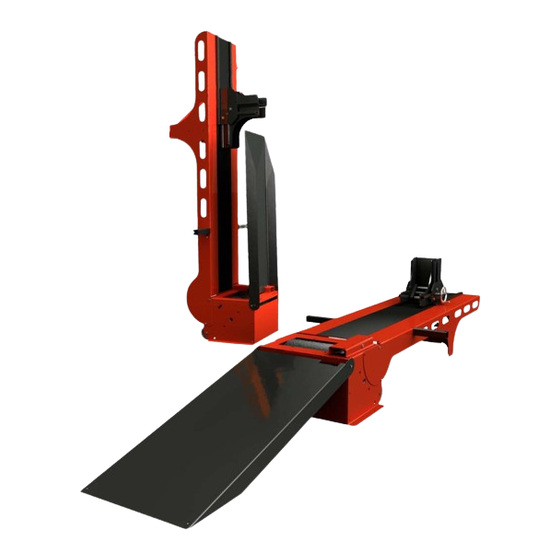
35.56 cm (14.00 in.) Frame structural steel Maximum Speed 175 KPH (109 MPH) Maximum Scooter Length (front of front 188.27 cm (74.125 in.) wheel to center of rear wheel) Remote Switches remote software control Model SD12 Scooter Dynamometer Installation Guide... - Page 13 (34.00 in) 335.92 cm (131.25 in) SD001 218.70 cm (86.10 in) 61.10 cm (24.05 in) 31.00 cm (12.21 in) Figure 1-1: Model SD12 Dyno Dimensions Folding Ramp Tie-Down Front Support SD002 Wheel Clamp Air Pump Option Stand Alone Blowers Option...
-
Page 14: Compressed Air Requirements
CD Rom Drive Printer Printer, if prints or needed Color printer, if prints are needed NVIRONMENTAL EQUIREMENTS description specifications Temperature operating min./max 10°C/50°C (50°F/122°F) storage min./max 0°C/60°C (32°F/140°F) Humidity 0 to 95% non condensing Model SD12 Scooter Dynamometer Installation Guide... -
Page 15: Forklift Requirements
NTERNET CCESS Dynojet recommends you have a phone close to the dyno to call for assistance in an emergency. You may also wish to contact Dynojet to troubleshoot your dyno. Internet access on your computer is desirable for contacting Dynojet and downloading new information and updates. -
Page 16: Dynoware Rt Electronics
More detailed information for configuring the DynoWare RT electronics can be found in the Power Core Help. main module air fuel ratio module speed pickup Figure 1-3: DynoWare RT Electronics Model SD12 Scooter Dynamometer Installation Guide... -
Page 17: Main Module Connections
Connect to the drum 1 and Refer to Do not press this button unless drum 2 speed inputs and Instructions instructed to do so by a Dynojet digital brake outputs. Technician. This button may need to be pressed to update the device. -
Page 18: Network Connections
ETWORK ONNECTIONS The Dynojet DynoWare RT dyno electronics connects to your computer directly or over a Local Area Network. If you have an existing network, connect the DynoWare RT main module to a router or a network switch on your network. If you don't have an existing network, you can create a network for the DynoWare RT by connecting the main module to a router. -
Page 19: Installation
This chapter is divided into the following categories: • Unpacking the Dyno, page 2-2 • Installation, page 2-5 • Cable Routing, page 2-8 • Ramp Installation, page 2-11 • Fold and Move the Dyno, page 2-12 Model SD12 Scooter Dynamometer Installation Guide... -
Page 20: Unpacking The Dyno
UNPACKING THE DYNO When you receive your dyno, examine the exterior of the shipping container for any visible damage. If damage is detected at this stage, contact the shipper or Dynojet before proceeding with unpacking. Use the following steps to unload your dyno. You will need to provide equipment capable of lifting a minimum of 454 kg (1000 pounds) to move the crated dyno into position in your dyno room. - Page 21 front support assembly P/N 61300035 pickup (2) P/N 76950203 drum unit assembly cable, CAN powersports P/N 62100009 P/N 76950680 dynoware RT main module cable, CAN control adapter P/N 66100016 P/N 76950807 Version 2 Model SD12 Scooter Dynamometer Installation Guide...
-
Page 22: Removing The Drum From The Crate
Using two people, carefully lift the drum off the crate and move into position in your dyno room. shaft hole steel bar SD018 Figure 2-1: Insert the Steel Bar and Lift the Drum off the Crate Model SD12 Scooter Dynamometer Installation Guide... -
Page 23: Installation
• 62100009 Drum Unit Assembly • 71300003 Wheel Clamp Assembly NSTALLING THE RONT UPPORT Place the front support on the drum. front support drum SD003 Figure 2-2: Place Front Support on the Drum Version 2 Model SD12 Scooter Dynamometer Installation Guide... - Page 24 Lift the spring plunger to slide the wheel clamp to a different position. Release the spring plunger to lock the wheel clamp in the new position. Note: The wheel clamp may already be installed. wheel clamp SD007 spring plunger Figure 2-4: Install the Wheel Clamp Model SD12 Scooter Dynamometer Installation Guide...
- Page 25 Secure the control cable to the inside of the front support using two cable ties. control lever control lever bracket control cable cable ties S 033 Figure 2-5: Install the Control Lever Bracket and Cable Version 2 Model SD12 Scooter Dynamometer Installation Guide...
-
Page 26: Cable Routing
Dynojet Powersports products to the DynoWare RT I - 76950798 CAN dyno user cable, 15' connects the air fuel module to the DynoWare RT using the CAN adapter cable or CAN network cable chain *optional accessory Model SD12 Scooter Dynamometer Installation Guide... -
Page 27: Routing The Cables
13b Insert the PCV CAN termination plug (K) in the PCV module. Note: If you are not using a PCV, be sure to save the PCV CAN termination plug (K) for future use. Version 2 Model SD12 Scooter Dynamometer Installation Guide... - Page 28 C H A P T E R 2 Cable Routing Figure 2-6: Routing Cables Model SD12 Scooter Dynamometer Installation Guide 2-10...
-
Page 29: Ramp Installation
Place the ramp on the drum. Install the ramp axle shaft. Secure the shaft in place using two retaining rings. ramp axle shaft axle shaft SD008 retaining ring Figure 2-7: Install the Ramp Version 2 Model SD12 Scooter Dynamometer Installation Guide 2-11... -
Page 30: Fold And Move The Dyno
Lift the spring plunger and slide the wheel clamp until it locks the ramp in place. Release the spring plunger. slide wheel slide wheel clamp to clamp forward lock ramp in place raise ramp lock front support in place SD021 Figure 2-8: Folding the Dyno Model SD12 Scooter Dynamometer Installation Guide 2-12... -
Page 31: Moving The Dyno
With the scooter dyno in the folded position, grab the front support leg brace. Tilt the dyno towards you. Roll the dyno to the desired position. front support leg brace front support leg brace S 035 Figure 2-9: Moving the Dyno Version 2 Model SD12 Scooter Dynamometer Installation Guide 2-13... -
Page 32: Opening The Dyno
Lower the ramp to the floor. Squeeze the control lever to release the front support. Lower the front support to the floor. slide wheel clamp forward control lever lower ramp S 036 Figure 2-10: Opening the Dyno Model SD12 Scooter Dynamometer Installation Guide 2-14... - Page 33 HAPTER ASIC PERATION The Dynojet Dynamometer gives you the state of the art technology, durability, and accuracy that you need. Dynojet’s advanced engineering delivers the precise horsepower measurements a technician needs to make quick and accurate evaluations of engine performance and drive train problems.
-
Page 34: Loading The Vehicle
Turn the wheel clamp handle until the front tire is held securely in the wheel clamp. slide the wheel clamp center drive axle wheel clamp on dyno drum handle Figure 3-1: Load the Vehicle Model SD12 Scooter Dynamometer Installation Guide... - Page 35 10 Tighten the tie-down straps evenly making sure the drive wheel remains centered on the drum. Never perform a dyno run if the tie-down straps are not in place or they are damaged. Figure 3-3: Attach the Tie-Downs Version 2 Model SD12 Scooter Dynamometer Installation Guide...
-
Page 36: Connecting The Rpm Pickup
Connecting the RPM Pickup CONNECTING THE RPM PICKUP Your Dynojet dynamometer includes a primary wire inductive pickup and two secondary wire inductive pickups. These small “clothespin like” inductive pickups are used to sense RPM. An RPM pickup is required if you want to view torque graphs. -
Page 37: Connecting The Secondary Inductive Pickup
Note: You must ground the vehicle to the dyno for the electronics to function properly. Refer to “Grounding the Vehicle” on page 3-7. connect secondary coil inductive pickup on the coil wire Figure 3-4: Connect the Secondary Inductive Pickup Version 2 Model SD12 Scooter Dynamometer Installation Guide... -
Page 38: Connecting The Primary Inductive Pickup
Note: You must ground the vehicle to the dyno for the electronics to function properly. Refer to “Grounding the Vehicle” on page 3-7. connect primary coil inductive pickup on the negative side of the coil Figure 3-5: Connect the Primary Inductive Pickup Model SD12 Scooter Dynamometer Installation Guide... -
Page 39: Grounding The Vehicle
Secure the grounding bracket to this location using one 1/4-20 x 1/2-inch screw. Attach the vehicle ground cable to an exhaust bolt or engine bolt on the vehicle. Attach the vehicle ground cable to the grounding bracket. Version 2 Model SD12 Scooter Dynamometer Installation Guide... -
Page 40: Pre-Run Inspection
• Perform any other safety inspections appropriate to running your vehicle on the dyno. Never allow any person(s) to stand behind the dyno or vehicle when it is being operated. Only the operator should be near the dyno or the vehicle during the test. Model SD12 Scooter Dynamometer Installation Guide... -
Page 41: Before Starting The Engine
• Fix any fuel, oil, or coolant leaks that may have shown up after engine warm up and check the carburetor for leaks. • Any loud or unusual engine noises or excessive exhaust smoke should be resolved before continuing. Version 2 Model SD12 Scooter Dynamometer Installation Guide... -
Page 42: Making A Test Run
• Perform any other safety checks that you deem appropriate to your particular situation. You are now ready to make a high speed run on the dyno. Refer to your Power Core Help for more detailed instructions. Model SD12 Scooter Dynamometer Installation Guide 3-10... -
Page 43: Preventative Maintenance
PREVENTATIVE MAINTENANCE This section contains basic preventative maintenance and troubleshooting information. To maintain proper dynamometer operation, Dynojet recommends you make routine checks of the dyno. • Drum—keep the drum clean and keep all objects clear of the drum. • Carriage Slide—keep the carriage slide clean and lightly lubricated. -
Page 44: Adjusting The Brake Tension
Back off the eyebolt nut until it no longer contacts the lever. eyebolt adjust brake tension here brake release pedal Figure 3-7: Adjust the Brake Tension Model SD12 Scooter Dynamometer Installation Guide 3-12... -
Page 45: Appendix A Reset Bearing Set Screws
Resetting the bearing set screws can alleviate bearing noise that may occur after an SD12 dyno is shipped. To ensure safety and accuracy in the procedures, perform the procedures as they are described. Be sure to read and understand the warnings included in this appendix. -
Page 46: Reset The Bearing Set Screws
Reset the Bearing Set Screws RESET THE BEARING SET SCREWS Resetting the bearing set screws can alleviate bearing noise that may occur after an SD12 dyno is shipped. Use the following instructions to access, loosen, and reset the bearing set screws. EMOVING THE... -
Page 47: Loosening The Brake Spring Eyebolt
Lock the front support and ramp into the upright position. Tip the dyno forward until the front support rests on the floor. This will expose the bottom of the drum module. SD037 Figure A-3: /Access the Bottom of the Drum Module Version 2 Model SD12 Scooter Dynamometer Installation Guide... -
Page 48: Loosening And Resetting The Set Screws
Using the access hole in the drum assembly, tighten the brake actuator spring eyebolt. Use the mark placed on the eyebolt. Refer to “Loosening the Brake Spring Eyebolt” on page A-3. Replace the brake pedal. Model SD12 Scooter Dynamometer Installation Guide... -
Page 49: Index
1-4 unpacking 2-2 weight 1-4 identifying cables 2-8 width 1-4 Industrial Noise Control, Inc. 1-3 dyno electronics 1-8 inspection 3-8 dyno room 1-3 intake air fan 1-3 equalizer box 1-3 exhaust extraction 1-3 Model SD12 Scooter Dynamometer Installation Guide Index-i... - Page 50 CAN termination plug 2-9 DynoWare RT power 2-8 identifying cables 2-8 network 2-8 PCV CAN termination plug 2-9 pendant 2-8 pickup card 2-8 remote atmos 2-8 RPM pickup 2-8 speed pickup, brake 2-8 Model SD12 Scooter Dynamometer Installation Guide Index-ii...
Need help?
Do you have a question about the sd12 and is the answer not in the manual?
Questions and answers