Table of Contents
Advertisement
Quick Links
Advertisement
Table of Contents
Troubleshooting

Related Manuals for Dynojet 200iX


Summary of Contents for Dynojet 200iX
- Page 2 Dynojet. Dynojet assumes no responsibility or liability for any error or inaccuracies that may appear in this manual. Except as permitted by such license, no...
-
Page 3: Table Of Contents
..........1-10 Above Ground Model 200iX/250iX Motorcycle Dynamometer Installation Guide... - Page 4 ........... . 2-63 Above Ground Model 200iX/250iX Motorcycle Dynamometer Installation Guide...
- Page 5 Troubleshooting CPI Fuses ........4-11 Version 1 Above Ground Model 200iX/250iX Motorcycle Dynamometer Installation Guide...
- Page 6 ..........C-7 Above Ground Model 200iX/250iX Motorcycle Dynamometer Installation Guide...
- Page 7 ..........Index-i Version 1 Above Ground Model 200iX/250iX Motorcycle Dynamometer Installation Guide...
-
Page 9: Warnings
Dynojet reserves the right to revise this publication and to make changes from time to time in the content hereof without obligation of Dynojet to notify any person of such revision or changes. - Page 10 To avoid ESD damage, always practice good ESD control precautions when servicing the dynamometer. Dynojet designs its dynamometers to be very tolerant of static shocks by the users, but the electronics are vulnerable when the electronics are exposed.
- Page 11 Do not repair or replace any part of the dynamometer or attempt any servicing unless specifically recommended in published user-repair instructions that you understand and have the skills to carry out. viii Version 1 Above Ground Model 200iX/250iX Motorcycle Dynamometer Installation Guide...
-
Page 13: Specifications And Operating Requirements
EQUIREMENTS Thank you for purchasing Dynojet’s Above Ground Model 200iX/250iX Motorcycle Dynamometer. Dynojet’s software and dynamometers will give you the power to get the maximum performance out of vehicles you evaluate. Whether you are new to the benefits of a chassis dynamometer or an experienced performance leader, the repeatability and diagnostic tools of WinPEP 7 software and a Dynojet dynamometer will give you the professional results you are looking for. -
Page 14: Introduction
UARD AFETY WITCH This appendix describes the procedures for installing the EEC finger guards and door safety switch. HETA ONTROLLER This appendix describes how to make power adjustments to the theta controller. Above Ground Model 200iX/250iX Motorcycle Dynamometer Installation Guide... -
Page 15: Conventions Used In This Manual
For assistance, please contact Dynojet Technical Support at 1-800-992-3525, or write to Dynojet at 2191 Mendenhall Drive, North Las Vegas, NV 89081. Visit us on the World Wide Web at www.dynojet.com and www.winpep.com where Dynojet provides state of the art technical support, on-line shopping, 3D visualizations, and press releases about our latest product lines. -
Page 16: Your Dyno Room
This section is not meant to imply that a dyno room is essential to repeatable results on a Dynojet dynamometer. However, a dyno room with an engine cooling intake fan, exhaust extraction, and noise reduction capabilities can add a new dimension to your shop. -
Page 17: Dynamometer Specifications And Requirements
ATTERY EQUIREMENTS Your 200iX/250iX dyno is designed to carry a group 24 deep-cycle discharge series battery for operating the starter, power carriage, and optional wheel clamp. The typical dimensions for this series of batteries are 27 cm long by 17 cm wide by 23 cm tall (10.625-inches by 6.75-inches by 9.125-inches). - Page 18 C H A P T E R 1 Dynamometer Specifications and Requirements Figure 1-1: Model 250iX Dyno Dimensions Above Ground Model 200iX/250iX Motorcycle Dynamometer Installation Guide...
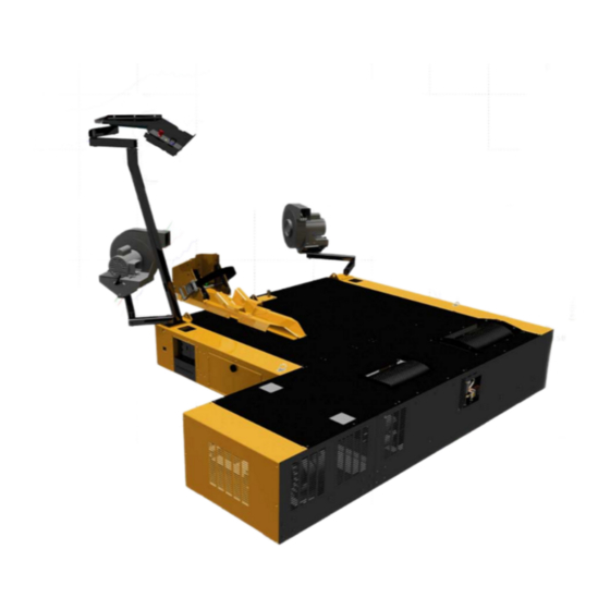
- Page 19 Folding Ramp Option (iX Module) Model 250i Dyno Trike Adapter iX Drum Module Assembly Air Pump Option Air Brake Option (not shown) (not shown) Figure 1-2: Model 250iX Dyno with Accessories Version 1 Above Ground Model 200iX/250iX Motorcycle Dynamometer Installation Guide...
-
Page 20: Compressed Air Requirements
LECTRICAL EQUIREMENTS The Model 200iX/250iX dynamometers require a 240V - 30a single-phase electrical circuit for reliable and precise operation. No other loads should be plugged into these circuits and these circuits should be independent of the lighting in the dyno room. -
Page 21: Environmental Requirements
NTERNET CCESS Dynojet recommends you have a phone close to the dyno to call for assistance in an emergency. You may also wish to contact Dynojet to troubleshoot your dyno. Internet access on your computer is desirable for contacting Dynojet and downloading new information and updates. -
Page 22: Dyno Electronics
RPM inductive system expansion 25-pin socket pickup socket connector atmospheric sensing module RPM module input/output module CPU module power 9-pin RS-232 socket 3-pin power plug Figure 1-3: The Dyno Electronics 1-10 Above Ground Model 200iX/250iX Motorcycle Dynamometer Installation Guide... - Page 23 MC120 dyno electronics enclosure dyno electronics enclosure Figure 1-4: Location of Dyno Electronics 1-11 Version 1 Above Ground Model 200iX/250iX Motorcycle Dynamometer Installation Guide...
-
Page 25: Installation
• Monitor Support, Tray, and Control Panel, page 2-52 • High Pressure Blowers, page 2-58 • Ground Hook Installation, page 2-60 • Final Adjustments and Tests, page 2-61 • Zip Tube, page 2-63 Above Ground Model 200iX/250iX Motorcycle Dynamometer Installation Guide... -
Page 26: Dyno Installation
........When you receive your dyno, examine the exterior of the shipping container for any visible damage. If damage is detected at this stage, contact the shipper or Dynojet before proceeding with unpacking. - Page 27 Remove the six 1/4-inch screws securing the center panel on the dyno and remove the center panel. Note: Dynojet recommends using a T30 Torx driver (Snap-On PFTx30E) to remove the 1/4-inch screws. For dynos with serial numbers lower than 2030152, Dynojet recommends using a hardened 5/32-inch hex driver (such as Snap-On FA5E).
- Page 28 Remove the two top screws securing each side drum cover to the dyno and set aside. top drum cover side drum cover side drum cover Figure 2-3: Remove the Top Drum Cover Above Ground Model 200iX/250iX Motorcycle Dynamometer Installation Guide...
- Page 29 Verify the contents of the hardware boxes and set aside. side drum cover dyno number stamped on frame side drum cover access holes in drum bulkhead (only two visible from this view) Figure 2-4: Remove the Side Drum Covers Version 1 Above Ground Model 200iX/250iX Motorcycle Dynamometer Installation Guide...
- Page 30 P/N 79190001 P/N 43816430 see list of parts below receptacle, turnlok, 30A, power carriage 125/250V P/N 82943001 P/N 43826430 optional accessory control pod spindle banner, dynojet (2) assembly P/N D706 P/N 61329000 Above Ground Model 200iX/250iX Motorcycle Dynamometer Installation Guide...
- Page 31 The following parts are included in the Monitor Arm Assembly P/N 61329003: washer, 1.87 x 1.25 ID x .12 monitor arm (2) THK (3) P/N 61329100 P/N 26215520 cap plug, 1.75 x 1/2” (4) monitor support P/N 35521420 P/N 61329500 Version 1 Above Ground Model 200iX/250iX Motorcycle Dynamometer Installation Guide...
- Page 32 3/8" (2) P/N 10111 P/N 37513200 D-ring bracket, surface washer, 5/16", flat (2) mount P/N DM150-002-007 P/N 10112 washer, 3/8", splitlock, bolt, 3/8-16 x 1", hex (2) steel (2) P/N DM150-019-012 P/N 36932100 Above Ground Model 200iX/250iX Motorcycle Dynamometer Installation Guide...
-
Page 33: Removing The Dyno From The Crate
(5000 lbs.) to lift the dyno off the crate and into position in your dyno room. You will also need a pair of straps capable of supporting 2268 kg (5000 lbs.) to attach to the dyno. Dynojet recommends using a single loop style strap. RECORD Be sure you record the dynamometer number on the inside cover of this manual. - Page 34 Figure 2-6: Loop Strap Placement Carefully lift the dyno off the crate. Figure 2-7: Lift the Dyno off the Crate 2-10 Above Ground Model 200iX/250iX Motorcycle Dynamometer Installation Guide...
- Page 35 Figure 2-8: Route the Power Cable 2-11 Version 1 Above Ground Model 200iX/250iX Motorcycle Dynamometer Installation Guide...
-
Page 36: Pickup Card
Figure 2-9: Install the Pickup Card 2-12 Above Ground Model 200iX/250iX Motorcycle Dynamometer Installation Guide... -
Page 37: Compressed Air Pump Assembly
To ensure accurate readings, pump maintenance should be performed every six months, or sooner, depending on usage. Refer to the Compressed Air Air Fuel Ratio Module Installation and User Guide (P/N 98200006). 2-13 Version 1 Above Ground Model 200iX/250iX Motorcycle Dynamometer Installation Guide... -
Page 38: Compressed Air Requirements
If not already removed, remove the eight screws securing the drum module panel to the dyno. Set the screws and the panel aside. Secure the pump housing to the dyno using four 1/4-20 torx screws. pump housing Figure 2-10: Install the Pump Housing 2-14 Above Ground Model 200iX/250iX Motorcycle Dynamometer Installation Guide... - Page 39 11 Replace the drum module panel using the screws removed earlier. copper sample tube silicon tube solenoid connector sensor attach air Figure 2-11: Installing the Sensor and Copper Sample Tube 2-15 Version 1 Above Ground Model 200iX/250iX Motorcycle Dynamometer Installation Guide...
-
Page 40: Installing The Air Hose With The Air Brake
AP115 air hose to the pump air hose to the pump Figure 2-12: Installing the Air Hose with the Air Brake 2-16 Above Ground Model 200iX/250iX Motorcycle Dynamometer Installation Guide... -
Page 41: Eddy Current Brake
Current Brake Cables” on page 2-38. You will need to provide equipment capable of lifting the eddy current brake off the crate and into position in your dyno room. You will also need a pair of straps. Dynojet recommends using continuous nylon loop style straps. -
Page 42: Unpacking The Eddy Current Brake
For more information on mounting the theta controller refer to page 2-24. RECORD Be sure you record the eddy current brake number on the inside cover of this manual. top cover eddy current brake number Figure 2-13: Remove the Covers 2-18 Above Ground Model 200iX/250iX Motorcycle Dynamometer Installation Guide... - Page 43 Remove the starter brace and set aside. starter brace line up panels EB141 lifting eye remove bolts, washers, and lifting eye nuts from dyno frame Figure 2-14: Move the Brake Next to the Dyno 2-19 Version 1 Above Ground Model 200iX/250iX Motorcycle Dynamometer Installation Guide...
-
Page 44: Installing The Eddy Current Brake
RAKE Insert the key into the keyway on the drum shaft. Use a c-clamp to press the key in. keyway on dyno shaft EB142 connector plate Figure 2-15: Install the Key 2-20 Above Ground Model 200iX/250iX Motorcycle Dynamometer Installation Guide... - Page 45 Secure the starter brace to the starter using the washer and nut removed earlier. starter brace connector plate EB143 three bolts not visible from this view Figure 2-16: Secure the Connector Plates and Starter Brace 2-21 Version 1 Above Ground Model 200iX/250iX Motorcycle Dynamometer Installation Guide...
- Page 46 10 Replace the existing set screws on the driveline assembly with the thread-lock set screws provided. 11 Tighten the driveline assembly set screws. dyno shaft brake shaft set screw Figure 2-18: Tighten the Set Screws 2-22 Above Ground Model 200iX/250iX Motorcycle Dynamometer Installation Guide...
-
Page 47: Securing The Drum And Brake Module To The Floor
ODULE TO THE LOOR Dynojet recommends you anchor the eddy current brake, along with the dyno, to the floor in your dyno room using concrete anchors. You will want to drill the holes and secure the dyno before placing the covers on your dyno. -
Page 48: Installing The Theta Controller
Secure the theta controller to the drum module bulkhead using four 8-32 x 3/8-inch screws. " four 8-32 x 3/8 screws theta controller EB146 Figure 2-20: Installing the Theta Controller 2-24 Above Ground Model 200iX/250iX Motorcycle Dynamometer Installation Guide... -
Page 49: Remove The Dyno Covers
Remove the twelve screws securing the side cover to the dyno and set aside. Remove the side cover and set aside. KD035 top cover side cover Figure 2-21: Removing the Dyno Covers 2-25 Version 1 Above Ground Model 200iX/250iX Motorcycle Dynamometer Installation Guide... -
Page 50: Drum Module Installation
........Examine the exterior of the shipping container for any visible damage. If damage is detected at this stage, contact the shipper or Dynojet before proceeding with unpacking. - Page 51 Remove the crate braces that support the top portion of the crate. Remove the four lag bolts and washers securing the drum to the crate base using a 9/16-inch socket, open or box end wrench. 2-27 Version 1 Above Ground Model 200iX/250iX Motorcycle Dynamometer Installation Guide...
-
Page 52: Installing The Ix Drum Module
10 Continue sliding the drum module towards the dyno until the side panels on the drum module and the dyno are flush. existing screws woodruff key driveline woodruff key KD036 iX drum module existing screws Figure 2-22: Installing the Driveline and the Drum Module 2-28 Above Ground Model 200iX/250iX Motorcycle Dynamometer Installation Guide... - Page 53 15 Replace the existing set screws on the driveline assembly with the thread-lock set screws provided. 16 Tighten the driveline set screws. not visible from this view KD037 secure connector plate Figure 2-23: Securing the Drum Module to the Dyno 2-29 Version 1 Above Ground Model 200iX/250iX Motorcycle Dynamometer Installation Guide...
-
Page 54: Installing The Bulkheads
Secure the middle bulkhead to the dyno frame using five 1/4-20 x 5/8-inch pan- head screws. KD038 monitor support brace front bulkhead middle bulkhead Figure 2-24: Securing the Front and Middle Bulkheads 2-30 Above Ground Model 200iX/250iX Motorcycle Dynamometer Installation Guide... - Page 55 Remove the existing 3/8-inch screw from the drum module and secure the toe kick bracket to the drum module. KD039 toe kick bracket Figure 2-25: Securing the Toe Kick Bracket 2-31 Version 1 Above Ground Model 200iX/250iX Motorcycle Dynamometer Installation Guide...
- Page 56 • Connect the green/yellow wire to ground Secure the dyno side cover to the bulkheads using the eleven screws removed earlier KD040 dyno side cover fan socket Figure 2-26: Securing the Dyno Side Cover 2-32 Above Ground Model 200iX/250iX Motorcycle Dynamometer Installation Guide...
- Page 57 10 Secure the drum side cover to the drum module using the eight 1/4-20 x 5/8-inch button-head screws removed earlier. dyno top cover KD041 drum side cover Figure 2-27: Securing the Dyno Top Cover and Drum Side Cover 2-33 Version 1 Above Ground Model 200iX/250iX Motorcycle Dynamometer Installation Guide...
-
Page 58: Routing Cables
Open the control panel interface (CPI) front panel to access the breakers and Breakout board. monitor support and tray control panel control panel interface dyno (CPI) electronics Figure 2-28: Dyno Room Layout 2-34 Above Ground Model 200iX/250iX Motorcycle Dynamometer Installation Guide... -
Page 59: Battery Requirements
ATTERY EQUIREMENTS The model 200iX/250iX dyno is designed to carry a group 24 deep cycle discharge series battery for operating the starter, optional power carriage, and optional wheel clamp. The typical dimensions for this series of batteries are 10 5/8-inches long by 6 3/4-inches wide by 9 1/8-inches tall. - Page 60 Secure the red battery cable to the positive (+) battery post. Secure the black battery cable to the negative (-) battery post. Secure the battery to the tray with the battery hold-down. battery KD043 Figure 2-29: Install the Battery 2-36 Above Ground Model 200iX/250iX Motorcycle Dynamometer Installation Guide...
-
Page 61: Routing The Pendant, Rs232 Computer Cable, And Control Panel Cable
9-pin RS232 cable to your computer 15-pin control panel cable labelled Button Panel P1 KD044 Figure 2-30: Route the Control Panel and Pendant Cables 2-37 Version 1 Above Ground Model 200iX/250iX Motorcycle Dynamometer Installation Guide... - Page 62 Note: For more information on wiring the Breakout board refer to page 2-39. theta controller input power temperature sensor cable KD045 control cable eddy current brake cable breakout board Figure 2-31: Route the Eddy Current Brake Cables 2-38 Above Ground Model 200iX/250iX Motorcycle Dynamometer Installation Guide...
-
Page 63: Wiring The Breakout Board
J2 J1 temp eddy current brake only or eddy current brake and air brake with control panel pickup card air brake load control only Figure 2-32: Wire the Breakout Board 2-39 Version 1 Above Ground Model 200iX/250iX Motorcycle Dynamometer Installation Guide... -
Page 64: Routing The Power Carriage And Wheel Clamp Cables
Route the power carriage and wheel clamp cables through the opening in the front of the dyno. route cables through cable pass through cover KD046 Figure 2-33: Remove the Cable Pass Through Cover 2-40 Above Ground Model 200iX/250iX Motorcycle Dynamometer Installation Guide... - Page 65 Secure the cable pass through cover to the dyno with the two screws removed earlier. 2-pin wheel clamp cable KD047 3-pin power carriage cable Figure 2-34: Routing Wheel Clamp and Power Carriage Cables 2-41 Version 1 Above Ground Model 200iX/250iX Motorcycle Dynamometer Installation Guide...
-
Page 66: Side And Top Cover Installation
Secure the eddy current brake side cover to the eddy current brake using the eight 1/4-20 x 5/8-inch screws removed earlier. KD048 Figure 2-35: Secure the Eddy Current Brake Side Cover 2-42 Above Ground Model 200iX/250iX Motorcycle Dynamometer Installation Guide... - Page 67 Secure the eddy current brake top cover to the eddy current brake six 1/4-20 x 5/8-inch screws removed earlier. KD049 Figure 2-36: Secure the Eddy Current Brake Top Cover 2-43 Version 1 Above Ground Model 200iX/250iX Motorcycle Dynamometer Installation Guide...
- Page 68 Figure 2-37: Secure the Dyno Drum Top Cover Secure the center cover to the dyno using the six 1/4-20 x 5/8-inch screws removed earlier. KD051 Figure 2-38: Secure the Dyno Top Center Cover 2-44 Above Ground Model 200iX/250iX Motorcycle Dynamometer Installation Guide...
-
Page 69: Installing The Ix Covers
Secure the drum top cover to the drum module using the six 1/4-20 x 5/8-inch screws removed earlier. drum top cover KD052 Figure 2-39: Securing the Drum Module Top Cover 2-45 Version 1 Above Ground Model 200iX/250iX Motorcycle Dynamometer Installation Guide... - Page 70 Place the drum safety cover over the drum. This cover has two pins to keep it in place. Risk of injury. Never run a motorcycle on the dyno without this cover in place. drum safety cover KD054 Figure 2-41: Installing the Drum Safety Cover 2-46 Above Ground Model 200iX/250iX Motorcycle Dynamometer Installation Guide...
-
Page 71: Trike Carriage Adapter And Carriage Assembly
Lube the tracks with the included lube or use grease. 5/16 x 1-inch bolts trike carriage adapter assembly 3/8 x 1-inch bolts Figure 2-42: Installing the Trike Carriage Adapter Assembly 2-47 Version 1 Above Ground Model 200iX/250iX Motorcycle Dynamometer Installation Guide... -
Page 72: Installing The Carriage Assembly
Remove the four 1/4 x 20-inch button-head screws securing the bearing bracket. Remove the bearing bracket and the carriage screw. screw carriage screw bearing bracket Figure 2-43: Remove the Bearing Bracket and Carriage Screw 2-48 Above Ground Model 200iX/250iX Motorcycle Dynamometer Installation Guide... - Page 73 1/4-20 x 1/2-inch button-head screws removed earlier. Note: If you ordered the power carriage accessory, refer to “Power Carriage” on page 3-42 for installation instructions KD056 Figure 2-44: Installing the Carriage Assembly 2-49 Version 1 Above Ground Model 200iX/250iX Motorcycle Dynamometer Installation Guide...
- Page 74 10 Secure the tire lock to the carriage using four 3/8-16 x 1/2-inch button-head flange bolts. Note: If you purchased the wheel clamp accessory, refer to “Wheel Clamp” on page 3-47 for installation instructions. KD057 Figure 2-45: Install the Tire Lock and Tire Stop 2-50 Above Ground Model 200iX/250iX Motorcycle Dynamometer Installation Guide...
-
Page 75: Tie-Down Installation
Refer to step 1 on page 2-52 for more information. tie-down under monitor support tie-down on right side of dyno Figure 2-46: Installing the Tie-Downs 2-51 Version 1 Above Ground Model 200iX/250iX Motorcycle Dynamometer Installation Guide... -
Page 76: Monitor Support, Tray, And Control Panel
Secure the monitor support to the dyno using four 3/8-16 x 1.25-inch button-head flange bolts. Note: Make sure the tie-down is sandwiched in between the dyno panel and the monitor support base. 2-52 Above Ground Model 200iX/250iX Motorcycle Dynamometer Installation Guide... - Page 77 Insert the pin on the monitor tray into the upper blower arm. tray washers arms washer monitor support tie-down under monitor support Figure 2-47: Installing the Monitor Support and Tray 2-53 Version 1 Above Ground Model 200iX/250iX Motorcycle Dynamometer Installation Guide...
- Page 78 10 Attach the control panel cable to the Button board. access hole button board control panel cable with cable harness wrap cable tie CP030 Figure 2-49: Attach the Control Panel Cable to the Button Board 2-54 Above Ground Model 200iX/250iX Motorcycle Dynamometer Installation Guide...
- Page 79 Note: If you plan on routing your cables through a zip tube refer to “Zip Tube” on page 2-63 and skip the following steps. 16 Route the cable bundle along the support arms with service loops to allow movement as shown below. 2-55 Version 1 Above Ground Model 200iX/250iX Motorcycle Dynamometer Installation Guide...
- Page 80 CP023 install control panel spindle if you did not purchase the monitor tray KD058 Figure 2-51: Install the Control Panel 2-56 Above Ground Model 200iX/250iX Motorcycle Dynamometer Installation Guide...
- Page 81 You may want to route the RS232 connector to your computer part way up the support arm along with the control panel and pendant cables depending on where you your computer is located. pendant KD059 Figure 2-52: Route the Pendant Cable 2-57 Version 1 Above Ground Model 200iX/250iX Motorcycle Dynamometer Installation Guide...
-
Page 82: High Pressure Blowers
Note: To allow full extension of the right blower, use the blower extension cord (P/N 76950317). This extension cord is only used with the blower mounted on the right side of the dyno. 2-58 Above Ground Model 200iX/250iX Motorcycle Dynamometer Installation Guide... - Page 83 1/4-inch thick poly washer blower arm plug power cord from use two on non monitor blower into dyno chassis arm side Figure 2-53: Installing the Blowers 2-59 Version 1 Above Ground Model 200iX/250iX Motorcycle Dynamometer Installation Guide...
-
Page 84: Ground Hook Installation
Install the Red Head anchors. Refer to Appendix A for installation instructions. Secure each ground hook to the floor using two 3/8-16 x 1-inch hex bolts, two 5/16-inch flat washers, and two 3/8” lock washers. Figure 2-54: Ground Hook Placement 2-60 Above Ground Model 200iX/250iX Motorcycle Dynamometer Installation Guide... -
Page 85: Final Adjustments And Tests
Turn on the main circuit breaker inside the CPI door. Note: Use the main circuit breaker to turn power on and off to the dyno. KD055 power plug main circuit breaker Figure 2-55: Turn on the Dyno Power 2-61 Version 1 Above Ground Model 200iX/250iX Motorcycle Dynamometer Installation Guide... -
Page 86: High Pressure Blower Test
Press and hold the right hand wheel clamp button then press the left hand button to open the clamp. Refer to “Using the Wheel Clamp” on page 4-6 for more information on using the Control Panel. 2-62 Above Ground Model 200iX/250iX Motorcycle Dynamometer Installation Guide... -
Page 87: Zip Tube
Pull the cable wrap tool through the zip tube along the length of the cables. guide body zip tube cable wrap tool end of cables Figure 2-57: Secure the Cable(s) Into the Zip Tube 2-63 Version 1 Above Ground Model 200iX/250iX Motorcycle Dynamometer Installation Guide... - Page 89 CCESSORIES This chapter discusses the various optional accessories that are available for the Dynojet Motorcycle Dynamometer (dyno) to meet your individual needs. All of these options can be added at the factory at the time of original dyno purchase, or purchased separately and added at any time thereafter.
-
Page 90: Main Dyno Power
Disconnect the power plug to ensure all power has been removed from the dyno before performing certain installation procedures. KD055 power plug main breaker Figure 3-1: Main Dyno Power Above Ground Model 200iX/250iX Motorcycle Dynamometer Installation Guide... -
Page 91: Air Brake
Attach the 4-pin connector to port P7 on the CPI board. PD149 P7 on the CPI board brake wiring block on breakout board Figure 3-2: Route the Air Brake Cable Version 1 Above Ground Model 200iX/250iX Motorcycle Dynamometer Installation Guide... - Page 92 You will need to provide an air hose nipple (1/4-inch NPT) to connect your clean, dry shop air supply (60 psi, 415 kilopascal, max constant line pressure) to the dynamometer. bulkhead fitting air hose access hole air brake Figure 3-3: Connect the Air Hose Above Ground Model 200iX/250iX Motorcycle Dynamometer Installation Guide...
-
Page 93: Installing The Emergency Stop Sticker
Remove the four screws securing the Button board to the control panel and set aside. Remove the Button board and set aside. button board screw CP032 Figure 3-5: Removing the Button Board Version 1 Above Ground Model 200iX/250iX Motorcycle Dynamometer Installation Guide... - Page 94 CP033 Figure 3-6: Removing the Switch Body Place the emergency stop sticker over the dyno shutdown sticker. place emergency stop sticker here CP015 Figure 3-7: Placing the Emergency Stop Sticker Above Ground Model 200iX/250iX Motorcycle Dynamometer Installation Guide...
- Page 95 Figure 3-8: Replacing the Emergency Stop Button Secure the Button board to the control panel using the four screws removed earlier. button board screw CP032 Figure 3-9: Securing the Button Board Version 1 Above Ground Model 200iX/250iX Motorcycle Dynamometer Installation Guide...
-
Page 96: Air Brake Final Adjustments And Tests
If the pads touch the rotor during a run, the information provided by the dyno will be inaccurate. Refer to page 3-15 for instructions on adjusting the brake pad clearance. Above Ground Model 200iX/250iX Motorcycle Dynamometer Installation Guide... -
Page 97: Changing The Brake Pads
Remove the hairpin cotter and loosen the castle nut until the pads clear the rotor. outboard brake pad adjust castle nut remove hairpin cotter Figure 3-11: Loosen the Castle Nut Version 1 Above Ground Model 200iX/250iX Motorcycle Dynamometer Installation Guide... - Page 98 The spring is located on the drum side of the brake assembly. Note: For clarity, the drum is not shown. nut, washer, and spring bolt nut, washer, and spring bolt Figure 3-12: Remove the Brake Spring 3-10 Above Ground Model 200iX/250iX Motorcycle Dynamometer Installation Guide...
- Page 99 Note: For clarity, the drum and parts of the dyno frame are not shown. brake bracket brake caliper stop Figure 3-13: Remove the Brake Caliper Stop 3-11 Version 1 Above Ground Model 200iX/250iX Motorcycle Dynamometer Installation Guide...
- Page 100 Air Brake Remove the hairpin cotter from the bottom clevis pin located on the front of the air brake assembly. bottom clevis pin hairpin cotter Figure 3-14: Remove the Bottom Hairpin Cotter 3-12 Above Ground Model 200iX/250iX Motorcycle Dynamometer Installation Guide...
- Page 101 Figure 3-15: Remove the Bottom Pin and the Top Hairpin Cotter Remove the top clevis pin. top clevis pin Figure 3-16: Remove the Top Clevis Pin 3-13 Version 1 Above Ground Model 200iX/250iX Motorcycle Dynamometer Installation Guide...
- Page 102 17 Tighten the castle nut and replace the hair pin cotter. Refer to Figure 3-11. 18 Adjust the brake pad clearance. Refer to page 3-15 for complete instructions. 19 Replace the top and right side covers. 20 Connect your shop air. 3-14 Above Ground Model 200iX/250iX Motorcycle Dynamometer Installation Guide...
-
Page 103: Adjusting The Brake Pad Clearance
If the pads touch the rotor during a run, the information provided by the dyno will be inaccurate. brake adjusting shim rotor inboard brake pad brake caliper stop bolts Figure 3-18: Adjust Brake Pad Clearance 3-15 Version 1 Above Ground Model 200iX/250iX Motorcycle Dynamometer Installation Guide... -
Page 104: Compressed Air Pump Assembly
Meter User Guide (P/N 98129104) to test your air pump for accuracy. Failure to follow proper procedures may result in inaccurate data or damage to the equipment. These manuals can be found on your WinPEP CD or at www.dynojet.com. The sensor and the copper sample tube are hot. Before touching the sensor or the sample tube, make sure it has cooled. -
Page 105: Extended Carriage
UPPORT AND RIKE ARRIAGE DAPTER SSEMBLY Secure the extension support to the dyno using seven 3/8 x 1/2-inch button-head flange bolts. extension support Figure 3-19: Installing the Extension Support 3-17 Version 1 Above Ground Model 200iX/250iX Motorcycle Dynamometer Installation Guide... - Page 106 Lube the tracks with the included lube or use grease. 5/16 x 1-inch bolts 3/8 x 1-inch bolts trike carriage adapter assembly extension support 5/16 x 1-inch bolts Figure 3-20: Install the Trike Carriage Adapter Assembly 3-18 Above Ground Model 200iX/250iX Motorcycle Dynamometer Installation Guide...
-
Page 107: Installing The Extended Carriage Assembly
1/4-20 x 1/2-inch button-head screws removed earlier. Run the extended carriage assembly through the full range of motion and verify there is no binding. Figure 3-21: Installing the Extended Carriage Assembly 3-19 Version 1 Above Ground Model 200iX/250iX Motorcycle Dynamometer Installation Guide... -
Page 108: Power Carriage
Loosen the set screw on the hand crank and remove the hand crank. Using a 7/16-inch wrench, remove the two bolts securing the flange bearing. flange bearing bolt hand crank Figure 3-22: Remove the Hand Crank 3-20 Above Ground Model 200iX/250iX Motorcycle Dynamometer Installation Guide... -
Page 109: Installing The Power Carriage
If the motor mount is already installed, skip this step and continue. Note: The flange bearing must be facing so the grease zerk is accessible (facing down). Note: Dynojet recommends using a 1/4-inch ratchet drive with an extension and a 7/16-inch shallow socket to secure the flange bearing bolts. flange bearing... - Page 110 Insert the plastic coupler spider on the carriage screw half of the coupler. power carriage cable strain relief motor assembly coupler spider cover PC038 Figure 3-24: Secure the Strain Relief 3-22 Above Ground Model 200iX/250iX Motorcycle Dynamometer Installation Guide...
- Page 111 10 Secure the motor assembly cover to the motor mount with four 1/4-20 x 1/2-inch button-head screws removed earlier. motor assembly motor assembly cover PC039 Figure 3-25: Assemble the Power Carriage 3-23 Version 1 Above Ground Model 200iX/250iX Motorcycle Dynamometer Installation Guide...
-
Page 112: Wheel Clamp
Bolt, 3/8-16 x 1", Hex (4) Remove the six 1/4-20 x 1-inch screws securing the wheel clamp cover. Remove the cover and set the cover and screws aside. cover Figure 3-26: Remove the Wheel Clamp Cover 3-24 Above Ground Model 200iX/250iX Motorcycle Dynamometer Installation Guide... - Page 113 Secure the wheel clamp to the carriage using four 3/8-16 x 1/2-inch bolts, lock washers and flat washers. wheel clamp WC013 Figure 3-27: Secure the Wheel Clamp to the Carriage 3-25 Version 1 Above Ground Model 200iX/250iX Motorcycle Dynamometer Installation Guide...
- Page 114 Install the wheel clamp cable strain relief to the side of the wheel clamp. Plug the wheel clamp cable into the connector on the wheel clamp motor. strain relief wheel clamp cable WC014 Figure 3-28: Install Wheel Clamp Strain Relief 3-26 Above Ground Model 200iX/250iX Motorcycle Dynamometer Installation Guide...
- Page 115 A C C E S S O R I E S Wheel Clamp Replace the wheel clamp cover. cover WC015 Figure 3-29: Replace the Wheel Clamp Cover 3-27 Version 1 Above Ground Model 200iX/250iX Motorcycle Dynamometer Installation Guide...
-
Page 116: Final Adjustments And Tests
Press and hold the right hand wheel clamp button then press the left hand button to open the clamp. Refer to “Using the Wheel Clamp” on page 4-6 for more information on using the control panel. 3-28 Above Ground Model 200iX/250iX Motorcycle Dynamometer Installation Guide... -
Page 117: Control Panel Interface Operation
Interface (CPI). To ensure safety and accuracy in the procedures, perform the procedures as they are described. This chapter is divided into the following categories: • Basic CPI Operation, page 4-2 • Power Distribution Assembly, page 4-8 • Maintenance and Troubleshooting, page 4-9 Above Ground Model 200iX/250iX Motorcycle Dynamometer Installation Guide... -
Page 118: Basic Cpi Operation
CAUTION FRONT WHEEL MUST BE SECURED AT ALL NOTICE TIMES. TIE DOWN STRAPS MUST BE Clean the A/F Ratio Pump USED TO STABILIZE THE MOTORCYCLE. filter regularly. Figure 4-1: Control Panel Features Above Ground Model 200iX/250iX Motorcycle Dynamometer Installation Guide... -
Page 119: Using The Air Fuel Ratio Air Pump
(P/N 98200006). Failure to follow proper procedures may result in inaccurate data or damage to the equipment. This manual can be found on your WinPEP CD or at www.dynojet.com. Version 1 Above Ground Model 200iX/250iX Motorcycle Dynamometer Installation Guide... -
Page 120: Using The Emergency Stop/Dyno Shutdown
CPI output is on. The blower outlets on the front of the dyno are designed to only work with Dynojet provided blowers. Connecting other electrical loads or other blowers to the outlets on the dyno may damage the dyno and void the warranty. -
Page 121: Using The Power Carriage
Press and hold the green starter button until the drum reaches maximum speed. Release the green starter button. Use the momentum of the drum to start the bike. Note: Do not re-engage the starter while the drum is turning. Version 1 Above Ground Model 200iX/250iX Motorcycle Dynamometer Installation Guide... -
Page 122: Using The Status Indicator
Risk of injury. Be sure the wheel clamp is free and clear of any obstruction. Do not operate the dyno if the wheel clamp indicator light is not on steady. Above Ground Model 200iX/250iX Motorcycle Dynamometer Installation Guide... - Page 123 The status indicator light will be blinking to indicate the wheel is not secured and a dyno run should not be attempted. Continue to open the clamp far enough to allow the next bike to be loaded easily. Version 1 Above Ground Model 200iX/250iX Motorcycle Dynamometer Installation Guide...
-
Page 124: Power Distribution Assembly
(right side of dyno as you are sitting on the bike) and the bottom breaker protects the left blower circuit. These breakers do not provide a manual disconnect. main dyno circuit breaker and disconnect PD047 blower circuit breakers right blower on top Figure 4-2: CPI Circuit Breakers Above Ground Model 200iX/250iX Motorcycle Dynamometer Installation Guide... -
Page 125: Maintenance And Troubleshooting
Pressing the clamp button again will secure the clamp. • If the E-Stop circuit is open or the Emergency Stop button is pressed, the wheel clamp will not operate. Version 1 Above Ground Model 200iX/250iX Motorcycle Dynamometer Installation Guide... -
Page 126: Replacing The Theta Controller Fuses
• Little Fuse, KLK 15 • Fast Blow, Dynojet P/N 54212501 • Fast Blow, Dynojet P/N 54211501 KD060 remove blanking plate reach through opening to theta controller fuses Figure 4-3: Replace Theta Controller Fuses 4-10 Above Ground Model 200iX/250iX Motorcycle Dynamometer Installation Guide... -
Page 127: Troubleshooting Cpi Fuses
Fuse F2 protects the power carriage drive circuit. If this fuse is open the power carriage motor will not activate. Replace with a 15A mini auto fuse. PD047 control panel F3, F4 interface board F1, F2 status light Figure 4-4: CPI Fuses 4-11 Version 1 Above Ground Model 200iX/250iX Motorcycle Dynamometer Installation Guide... -
Page 129: Basic Dyno Operation
This chapter is divided into the following categories: • Loading the Vehicle, page 5-2 • Connecting the RPM Pickup, page 5-4 • Pre-Run Inspection, page 5-7 • Making a Test Run, page 5-9 • Preventative Maintenance, page 5-10 Above Ground Model 200iX/250iX Motorcycle Dynamometer Installation Guide... -
Page 130: Loading The Vehicle
Drive the vehicle onto the dyno and align the vehicle straight with the dyno. Stop the vehicle when the drive axle is centered on the drum. adjust carriage all the way out center drive axle on dyno drum Figure 5-1: Load the Vehicle Above Ground Model 200iX/250iX Motorcycle Dynamometer Installation Guide... - Page 131 Tighten the four tie-down straps evenly making sure the drive wheels remain centered on the drum. Never perform a dyno run if the tie-down straps are not in place or they are damaged. Figure 5-2: Load the Vehicle—Top View Version 1 Above Ground Model 200iX/250iX Motorcycle Dynamometer Installation Guide...
-
Page 132: Connecting The Rpm Pickup
........Your Dynojet dynamometer includes a primary wire inductive pickup and two secondary wire inductive pickups. -
Page 133: Connecting The Secondary Inductive Pickup
Note: You must ground the vehicle to the dyno for the electronics to function properly. connect secondary coil inductive pickup on the coil wire connect secondary inductive pickup on the coil wires coil Figure 5-3: Connect the Secondary Inductive Pickup Version 1 Above Ground Model 200iX/250iX Motorcycle Dynamometer Installation Guide... -
Page 134: Connecting The Primary Inductive Pickup
Note: You must ground the vehicle to the dyno for the electronics to function properly. connect primary coil inductive pickup on the negative side of the coil Figure 5-4: Connect the Primary Inductive Pickup Above Ground Model 200iX/250iX Motorcycle Dynamometer Installation Guide... -
Page 135: Pre-Run Inspection
Never allow any person(s) to stand behind the dyno or vehicle when it is being operated. Only the operator should be near the dyno or the vehicle during the test. Version 1 Above Ground Model 200iX/250iX Motorcycle Dynamometer Installation Guide... -
Page 136: Before Starting The Engine
• Fix any fuel, oil, or coolant leaks that may have shown up after engine warm up and check the carburetor for leaks. • Any loud or unusual engine noises or excessive exhaust smoke should be resolved before continuing. Above Ground Model 200iX/250iX Motorcycle Dynamometer Installation Guide... -
Page 137: Making A Test Run
Using the vehicle’s own brakes to slow or stop the drum at speeds over 30 m.p.h. can severely over heat the brake parts. Dynojet dynamometers with the air brake or eddy current brake accessory can be used to slow the vehicle and drum to a full stop at any speed. -
Page 138: Preventative Maintenance
This section contains basic preventative maintenance and troubleshooting information for the wheel clamp and CPI fuses. To maintain proper dynamometer operation, Dynojet recommends you make routine checks of the dyno. • Drum—keep the drum clean and keep all objects clear of the drum. -
Page 139: Warnings
Anchor spacing and edge distance requirements (anchor installation locations) are the responsibility of the engineer of record. CONTACT INFORMATION FOR ITW RAMSET/RED HEAD Contact ITW Ramset/Red Head at 1-630-350-0370, or 1300 North Michael Drive, Wood Dale, IL 60191. Above Ground Model 200iX/250iX Motorcycle Dynamometer Installation Guide... - Page 140 Drill the hole in the concrete the same outside diameter as the anchor being used to any depth exceeding minimum embedment. Figure A-1: Red Head Anchor—Drill the Hole Insert the anchor. anchor Figure A-2: Red Head Anchor—Insert the Anchor Above Ground Model 200iX/250iX Motorcycle Dynamometer Installation Guide...
- Page 141 Note: Use only Ramset/Red Head setting tools to insure proper installtion. setting tool Figure A-4: Red Head Anchor—Expand the Anchor Version 1 Above Ground Model 200iX/250iX Motorcycle Dynamometer Installation Guide...
-
Page 143: Installation
This Appendix is divided into the following categories: • Locations Using 60 Hz Power (North America and Japan), page B-2 • Locations Using 50 Hz Power (Locations other than North America and Japan), page B-7. Above Ground Model 200iX/250iX Motorcycle Dynamometer Installation Guide... -
Page 144: Locations Using 60 Hz Power (North America And Japan
30A for proper operation. Failure to follow these instructions could result in personal injury or damage to the dyno. Connecting the dyno to the incorrect voltage will void the dyno warranty. Contact Dynojet with any questions. -
Page 145: Installing The Wall Receptacle
Connect the other 240V leg (line 2) to the Y terminal (gold colored screw). Connect the neutral conductor to the W or WH terminal (silver screw). Connect the ground conductor to the green grounding screw. Version 1 Above Ground Model 200iX/250iX Motorcycle Dynamometer Installation Guide... -
Page 146: Testing For Correct Voltages
You must have a licensed electrician correct the power connection. Connecting the dyno to the incorrect voltage can result in damage to the dyno and will void the dyno warranty. Contact Dynojet with any questions. Using a voltmeter that is capable of measuring AC voltage, measure between the points listed below and verify that the correct voltages are present. -
Page 147: Replacing The Power Plug
Refer to the previous table for testing and probe the new connections as follows: • blue wire as location #2 • brown wire as location #4 • black wire as location #1 • green/yellow wire as location #3 Version 1 Above Ground Model 200iX/250iX Motorcycle Dynamometer Installation Guide... -
Page 148: Connecting The Dyno
Turn on the main dyno breaker. Test the blowers for operation. Turn on the dyno electronics and verify operation. Test the control panel operations. For more information, refer to your dyno installation guide. Above Ground Model 200iX/250iX Motorcycle Dynamometer Installation Guide... -
Page 149: Locations Using 50 Hz Power (Locations Other Than North America And Japan
30A for proper operation. Failure to follow these instructions could result in personal injury or damage to the dyno. Connecting the dyno to the incorrect voltage will void the dyno warranty. Contact Dynojet with any questions. -
Page 150: Installing The Wall Receptacle
Connect the other 240V leg to the L terminal (no color). Connect the ground conductor to the green terminal. L terminal N terminal ground terminal (white) (green) Figure B-2: Wire the Wall Receptacle Above Ground Model 200iX/250iX Motorcycle Dynamometer Installation Guide... -
Page 151: Testing For Correct Voltages
Using a voltmeter that is capable of measuring AC voltage, measure between the points listed below and verify that the correct voltages are present. probe 1 probe 2 desired voltage measurement 220V to 250V <5V Figure B-3: Test the Wall Receptacle Version 1 Above Ground Model 200iX/250iX Motorcycle Dynamometer Installation Guide... -
Page 152: Replacing The Power Plug
Refer to the previous table for testing and probe the new connections as follows: • blue wire as location #1 • brown wire as location #3 • green/yellow wire as location #2 B-10 Above Ground Model 200iX/250iX Motorcycle Dynamometer Installation Guide... -
Page 153: Connecting The Dyno
Turn on the main dyno breaker. Test the blowers for operation. Turn on the dyno electronics and verify operation. Test the control panel operations. For more information, refer to your dyno installation guide. B-11 Version 1 Above Ground Model 200iX/250iX Motorcycle Dynamometer Installation Guide... -
Page 155: Appendix C Eec Finger Guard And Door Safety Switch Installation
NSTALLATION This appendix contains instructions for installing the European Economic Community (EEC) Kit to the model 200iX/250iX motorcycle dynamometer. This appendix will walk you through installing the EEC finger guards and door safety switch. The finger guards and door safety switch are required only for European dynamometers. -
Page 156: Eec Finger Guards
........The European model 200iX/250iX dynamometers require guards mounted on the front and back of the drum guard bracket. - Page 157 Remove the drum module hood and set aside. Note: For clarity, the eddy current brake and dyno are not shown. screw drum module hood Figure C-1: Remove the Drum Module Hood Version 1 Above Ground Model 200iX/250iX Motorcycle Dynamometer Installation Guide...
-
Page 158: Installing The Eec Finger Guards
Secure each EEC finger guard to the drum module hood using two 1/4-20 x 5/8-inch pan head screws. screw drum module hood finger guard Figure C-2: Secure the EEC Finger Guards to the Drum Module Hood Above Ground Model 200iX/250iX Motorcycle Dynamometer Installation Guide... - Page 159 The gap between the finger guards and the drum must be less than 0.64 centimeters. Refer to page C-6 for instructions on adjusting the gap. screw drum module hood Figure C-3: Replace the Drum Module Hood Version 1 Above Ground Model 200iX/250iX Motorcycle Dynamometer Installation Guide...
-
Page 160: Adjusting The Eec Finger Guards
Do not operate the dynamometer without the EEC finger guards properly installed. The gap between the finger guards and the drum must be less than 0.64 centimeters. adjust screw adjust clearance Figure C-4: Adjust the EEC Finger Guard Clearance Above Ground Model 200iX/250iX Motorcycle Dynamometer Installation Guide... -
Page 161: Door Safety Switch
Figure 3-5 on page 3-6 Remove the three screws securing the CPI cover and set aside. Remove the CPI cover and set aside. CPI cover Figure C-5: Remove the CPI Cover Version 1 Above Ground Model 200iX/250iX Motorcycle Dynamometer Installation Guide... - Page 162 The air brake should be applied holding the drum and the status light on the control panel will be flashing. 15 Depress the safety switch and the air brake will release and the status light will be on steady. Above Ground Model 200iX/250iX Motorcycle Dynamometer Installation Guide...
- Page 163 P P E N D I X HETA ONTROLLER This appendix describes how to make power adjustments on the theta controller. To ensure safety and accuracy in the procedures, perform the procedures as they are described. Above Ground Model 200iX/250iX Motorcycle Dynamometer Installation Guide...
- Page 164 CCESSING THE WITCHES Dynojet recommends you set the dip switches at the time of installation. The two dip switches are the only adjustments that can be altered. Be sure not to damage any other parts on the circuit board. Do not attempt any other adjustments.
- Page 165 LO, overheating and damage to the eddy current brake or fuse failure may result. Review the LO/NORM dip switch position setting and re- measure your incoming AC line voltage. Figure D-1: Theta Controller Dip Switch Settings Version 1 Above Ground Model 200iX/250iX Motorcycle Dynamometer Installation Guide...
- Page 167 2-48 circuit breakers 4-8 remove from crate 2-2 control panel 4-3 tire lock 2-50 installing 2-58 tire stop 2-50 testing 2-62 center cover using 4-4 dyno 2-44 iX dyno 2-46 Index-i Above Ground Model 200iX/250iX Motorcycle Dynamometer Installation Guide...
- Page 168 3-5 height 1-5 environmental requirements 1-9 installing 2-2 equalizer box 1-4 length 1-5 ESD precautions vi secure to floor 2-23 exhaust extration 1-4 unpacking 2-2 weight 1-5 width 1-5 Index-ii Above Ground Model 200iX/250iX Motorcycle Dynamometer Installation Guide...
- Page 169 50 Hz B-11 verifying operation, 60 Hz B-6 power cable, routing 2-11 jumpers 2-39 power carriage connecting the cable 3-22 flange bearing 3-20 hand crank 3-20 installing 3-21 Index-iii Version 1 Above Ground Model 200iX/250iX Motorcycle Dynamometer Installation Guide...
- Page 170 2-40 testing 2-62 RS232 2-37 temperature sensor 2-38 wheel clamp 2-40 unpacking dyno 2-2 RPM pickup using the dyno 5-9 connecting 5-4 primary inductive pickup 5-6 secondary inductive pickup 5-5 Index-iv Above Ground Model 200iX/250iX Motorcycle Dynamometer Installation Guide...
- Page 171 2-39 woodruff key 2-28 your dyno room 1-4 equalizer box 1-4 exhaust extraction 1-4 fire suppression 1-4 intake air fan 1-4 noise control 1-4 zip tube 2-63 Index-v Version 1 Above Ground Model 200iX/250iX Motorcycle Dynamometer Installation Guide...
Need help?
Do you have a question about the 200iX and is the answer not in the manual?
Questions and answers