Sign In
Upload
Manuals
Brands
Dynojet Manuals
Measuring Instruments
250i
Dynojet 250i Manuals
Manuals and User Guides for Dynojet 250i. We have
3
Dynojet 250i manuals available for free PDF download: Installation Manual
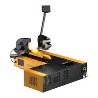
Dynojet 250i Installation Manual (184 pages)
Motorcycle Dynamometers
Brand:
Dynojet
| Category:
Measuring Instruments
| Size: 16 MB
Table of Contents
Table of Contents
3
Warnings
9
Introduction
14
Conventions Used in this Manual
15
Technical Support
15
Your Dyno Room
15
Battery Requirements
17
Chassis Specifications
17
Dynamometer Specifications and Requirements
17
Compressed Air Requirements
19
Computer Specifications
19
Electrical Requirements
19
Environmental Requirements
20
Forklift Requirements
20
Ground Hook Requirements
20
Phone and Internet Access
20
Tie-Down Straps
20
MODEL 200I MOTORCYCLE DYNAMOMETER
21
MODEL 250I MOTORCYCLE DYNAMOMETER
22
Installation
23
Dyno Installation
24
Unpacking and Inspecting Your Dyno
24
Removing the Dyno from the Crate
28
Routing the Power Cable
30
Positioning and Securing the Dyno
31
Battery
32
Installing the Battery
32
Pickup Card
33
Eddy Current Brake
35
Parts List
35
Unpacking the Eddy Current Brake
35
Installing the Eddy Current Brake
38
Securing the Drum and Brake Module to the Floor
41
Installing the Theta Controller
42
Installing the Support Arm and Tray
43
Parts List
43
Support Arm and Monitor Tray
43
Dyno Electronics
45
Routing Cables
47
Routing the Pendant, RS232 Computer Cable, and Control Panel Cable
47
Routing the Eddy Current Brake Cables
52
Wiring the Breakout Board
53
Tire Carriage Installation
56
Drum Side and Top Covers
60
Ramp Bracket
62
Ground Hooks
65
Zip Tube
66
Main Dyno Power
68
Remove and Replace Dyno and Drum Covers
69
Removing the Drum Top and Side Covers
69
Removing the Center Panel
71
Air Brake
73
Parts List
73
Routing the Air Brake Cable and Air Hose
74
Installing the Emergency Stop Sticker
76
Air Brake Final Adjustments and Tests
80
Changing the Brake Pads
81
Adjusting the Brake Pad Clearance
86
Air Pump and Filter Assembly
87
Installing the Filter and Pump Assemblies
88
Parts List
88
Cleaning the Filter Assembly
91
Pump Head Maintenance
92
Extended Carriage
94
Parts List
94
Removing the Standard Tire Carriage
95
Installing the Extended Carriage Support Bracket
97
Installing the Extended Carriage
100
High Pressure Blower
104
Parts List
104
Installing the Blower Arm Assemblies
105
Installing the High Pressure Blower Assemblies
106
Connecting Power to the Blowers
107
Installing the Power Carriage
110
Power Carriage
110
Wheel Clamp
113
Final Adjustments and Tests
115
Power Carriage Final Adjustments and Tests
115
Turning on the Dyno Power
115
Wheel Clamp Final Adjustments and Tests
115
Introduction
118
Basic Control Panel Operation
119
Using the Air Fuel Ratio Air Pump
120
Understanding Interlocks
121
Using the Emergency Stop/Dyno Shutdown
121
Using the High Pressure Blowers
121
Using the Power Carriage
122
Using the Starter
122
Using the Status Indicator
123
Using the Wheel Clamp
123
High Pressure Blower Circuit Breakers
125
Main Dyno Circuit Breaker
125
Power Distribution Assembly
125
Maintenance and Troubleshooting
126
Wheel Clamp
126
Replacing the Theta Controller Fuses
127
Troubleshooting CPI Fuses
128
Loading the Bike
130
Connecting the RPM Pickup
132
RPM Pickup Descriptions
132
Connecting the Secondary Inductive Pickup
135
Pre-Run Inspection
137
After Engine Warm up
138
Before Starting the Engine
138
Engine Warm up
138
Making a Test Run
139
Preventative Maintenance
140
Contact Information for ITW Ramset/Red Head
141
Warnings
141
Installation
142
Appendix B Power Requirements
145
Locations Using 60Hz Power (North America & Japan
146
Installing the Wall Receptacle
147
Testing for Correct Voltages
148
Replacing the Power Plug
149
Hard Wiring to the Building
149
Connecting the Dyno
150
Locations Using 50 Hz Power (Locations Other than North America and Japan
151
Installing the Wall Receptacle
152
Testing for Correct Voltages
153
Replacing the Power Plug
154
Hard Wiring to the Building
154
Connecting the Dyno
155
Appendix C Theta Controller
157
Power Adjustment
158
Accessing the Dip Switches
158
Appendix D EEC Kit
161
EEC Finger Guards Installation
162
Removing the Drum Module Hood
162
Installing the EEC Finger Guards
163
Adjusting the EEC Finger Guards
165
Door Safety Switch
166
Installing the Door Safety Switch
166
Appendix E Standard and Extended Tire Carriage Installation-Discontinued
169
Standard Tire Carriage-Discontinued
170
Installing the Standard Tire Carriage
170
Extended Tire Carriage-Discontinued
174
Installing the Extended Tire Carriage Support Bracket
174
Installing the Extended Tire Carriage
177
Index
181
Advertisement
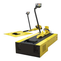
Dynojet 250i Installation Manual (176 pages)
above ground motorcycle dynamometers
Brand:
Dynojet
| Category:
Measuring Instruments
| Size: 8 MB
Table of Contents
Table of Contents
3
Warnings
7
Chapter 1 Specifications and Operating Requirements
12
Introduction
12
Technical Support
13
Conventions Used in this Manual
13
Your Dyno Room
14
Dynamometer Specifications and Requirements
15
Battery Requirements
15
Chassis Specifications
15
Compressed Air
18
Computer Specifications
18
Electrical Requirements
19
Environmental Requirements
19
Fire Suppression
19
Forklift Requirements
19
Grounding Requirements
20
Ground Hook Requirements
20
Phone and Internet Access
20
Tie-Down Straps
20
Tool Requirements
20
Model 200I Motorcycle Dynamometer
21
Power Cord
21
Model 250I Motorcycle Dynamometer
22
Dynoware RT Electronics
23
Main Module Connections
23
Network Connections
25
Chapter 2 Dyno Installation
28
Unpacking and Inspecting the Dyno
28
Dyno Installation
36
Removing the Dyno from the Crate
36
Battery Installation
39
Pickup Card Installation
40
Eddy Current Brake Installation
41
Unpacking the Eddy Current Brake
41
Installing the Eddy Current Brake
46
Secure the Dyno and Brake Module to the Floor
51
Support Arm and Monitor Tray Installation
52
Installing the Support Arm and Tray
52
Cable Routing
54
Identifying the Cables
54
Installing the Dynoware RT Main Module
56
Routing the Cables
56
Connecting the Control Panel Cable
56
Tire Carriage Installation
64
Side and Top Cover Installation
68
Load Cell Calibration
71
Ramp Bracket
76
Ground Hook Installation
79
Zip Tube
80
Chapter 3 Accessories
81
Main Dyno Power
82
Air Brake
83
Routing the Air Brake Cable and Air Hose
83
Installing the Emergency Stop Sticker
85
Air Brake Final Adjustments and Tests
89
Adjusting the Brake Pad Clearance
89
Air Fuel Ratio Module
96
Extended Carriage
97
Installing the Extended Carriage Support Bracket
98
Installing the Extended Carriage
100
Folding Ramp
104
Removing the Ramp from the Crate
104
High Pressure Blower
112
Installing the High Pressure Blowers
113
Power Carriage
115
Removing the Hand Wheel
116
Installing the Power Carriage
117
Wheel Clamp
119
Final Adjustments and Tests
121
Turning on the Dyno Power
121
Power Carriage Final Adjustments and Tests
121
Wheel Clamp Final Adjustments and Tests
121
Chapter 4 Control Panel Interface Operation
123
Introduction
124
Basic Control Panel Operation
125
Using the Emergency Stop/Dyno Shutdown
126
Using the High Pressure Blowers
127
Understanding Interlocks
127
Using the Power Carriage
128
Using the Starter
128
Using the Status Indicator
129
Using the Wheel Clamp
129
Power Distribution Assembly
131
Main Dyno Circuit Breaker
131
High Pressure Blower Circuit Breakers
131
Maintenance and Troubleshooting
132
Wheel Clamp
132
Replacing the Eddy Current Brake Driver Fuses
133
Troubleshooting CPI Fuses
134
Chapter 5 Basic Dyno Operation
135
Loading the Vehicle
136
Hapter
136
Connecting the RPM Pickup
138
RPM Pickup Descriptions
138
Connecting the Primary Inductive Pickup
139
Connecting the Secondary Inductive Pickup
141
Grounding the Vehicle
143
Pre-Run Inspection
144
Before Starting the Engine
145
Engine Warm up
145
After Engine Warm up
145
Using the Dyno
146
Using the Starter
146
Making a Test Run
147
Preventative Maintenance
148
Appendix A Red Head Anchor Installation
149
Warnings
149
Contact Information for ITW Ramset/Red Head
149
Appendix B Power Requirements and Installation
153
North America, Japan, and Locations Using 60 Hz Power
154
Installing the Wall Receptacle
154
Testing for Correct Voltages
155
Hard Wiring to the Building
156
Excluding North America and Japan
157
Installing the Wall Receptacle
158
Testing for Correct Voltages
159
Hard Wiring to the Building
159
Appendix C EEC Kit
161
EEC Finger Guards Installation
162
Removing the Drum Module Hood
162
Installing the EEC Finger Guards
164
Adjusting the EEC Finger Guards
165
Door Safety Switch
166
Installing the Door Safety Switch
166
Appendix D Torque Values
169
Standard Bolt Torque Values
170
Grade 5
170
Grade 8
170
Metric Bolt Torque Values
172
Index
173
Dynojet 250i Installation Manual (40 pages)
High Pressure Blower
Brand:
Dynojet
| Category:
Blower
| Size: 2 MB
Table of Contents
Table of Contents
3
Introduction
6
Conventions Used in this Manual
6
Tool Requirements
6
Technical Support
6
Main Dyno Power
7
Model 200I/250I Main Dyno Power-Above Ground
7
Model 200I/250I Main Dyno Power-In Ground
8
Model 200I/250I above Ground Blower Installation
9
Installing the High Pressure Blowers
10
Model 200I/250I in Ground Blower Installation
12
Mark and Drill Blower Mount Holes
13
Installing the Blower Mounts
14
Installing the Blower Assemblies
15
Routing the Blower Cables
16
Stand Alone Blower Installation
17
Installing the Blower and Base Assemblies
18
Installing the Extension
19
Power Hookup
19
Appendix A Red Head Anchor Installation
21
Warnings
21
Contact Information for ITW Ramset/Red Head
21
Appendix B Model 200Ix/250Ix Blower Installation
26
Model 200Ix/250Ix above Ground Blower Installation
26
Installing the Fan Arm Mounts
27
Installing the Blowers
28
Model 200Ix/250Ix in Ground Blower Installation
29
Installing the Left Blower Mount
30
Installing the Left Blower Assembly
31
Installing the Right Blower Mount and Blower Assembly
32
Cable Routing
34
Appendix C Model 200/250 Blower Installation
35
Modifying the Tire Stop
37
Installing the Extension Arm Assembly
38
Installing the Blower Assemblies
39
Power Hookup
40
Advertisement
Advertisement
Related Products
Dynojet 250
Dynojet 200
Dynojet 224
Dynojet 200iX
Dynojet 250iX
Dynojet 200i
Dynojet 24xLC2 Linx
Dynojet 200iPX
Dynojet 250iPX
Dynojet Wideband 2
Dynojet Categories
Motorcycle Accessories
Automobile Accessories
Control Unit
Measuring Instruments
Tuner
More Dynojet Manuals
Login
Sign In
OR
Sign in with Facebook
Sign in with Google
Upload manual
Upload from disk
Upload from URL