Rohde & Schwarz SMCV100B User Manual
Vector signal generator
Hide thumbs
Also See for SMCV100B:
- Getting started (81 pages) ,
- User manual (913 pages) ,
- User manual (913 pages)
Table of Contents
Advertisement
Quick Links
Advertisement
Chapters
Table of Contents

Related Manuals for Rohde & Schwarz SMCV100B


Summary of Contents for Rohde & Schwarz SMCV100B
- Page 1 ® R&S SMCV100B Vector Signal Generator User Manual (;Ý5ï2) 1179059702 Version 04...
- Page 2 ® This document describes the R&S SMCV100B, stock no. 1432.7000.02 and its options: ● ® R&S SMCVB-B103 Frequency range 4 kHz to 3 GHz (1433.2002.xx) ● ® R&S SMCVB-KB106 Frequency range extension to 6 GHz (1433.2202.xx) ● ® R&S SMCVB-KB107 Frequency range extension to 7 GHz (1433.2402.xx) ●...
-
Page 3: Table Of Contents
Preparing for use......................23 3.1.1 Lifting and carrying......................23 3.1.2 Unpacking and checking....................23 3.1.3 Choosing the operating site..................23 3.1.4 Setting up the R&S SMCV100B..................24 3.1.5 Considerations for test setup..................25 3.1.6 Connecting to power..................... 26 3.1.7 Connecting to LAN......................26 3.1.8 Connecting a monitor.................... - Page 4 "I/Q stream mapper" block.................... 61 3.4.7 I/Q modulator ("I/Q mod" block)..................61 3.4.8 RF ("RF" block)......................61 3.4.9 Applications examples of the R&S SMCV100B............61 Instrument control...................... 62 3.5.1 Possible ways to operate the instrument..............62 3.5.2 Means of manual interaction..................62 3.5.3...
- Page 5 ® Contents R&S SMCV100B Overview of the signal generation modes..............73 Accessing the functions in the baseband domain..........74 Generating signals according to broadcast standards...........75 Common functions and settings in the baseband domain........78 4.4.1 Basics on signals, modulation types and filters used the baseband domain....78 4.4.2...
- Page 6 ® Contents R&S SMCV100B 4.10.1 FM/PhiM/AM configuration and settings..............237 4.10.2 Pulse modulation configuration and settings...............241 4.11 Shifting and boosting the baseband signal............244 4.11.1 About baseband offsets....................244 4.11.2 Baseband offsets settings................... 246 4.11.3 How to improve signal characteristics by shifting the baseband signal...... 247 5 Configuring external baseband signals...........249...
- Page 7 ® Contents R&S SMCV100B 6.2.1 Required options......................294 6.2.2 About the linear I/Q impairments.................294 6.2.3 Digital impairments settings..................296 7 Applying I/Q vector modulation............298 Required options.......................298 About the I/Q modulator................... 298 I/Q modulator settings....................298 Optimizing I/Q modulation performance..............301 8 Configuring the RF signal..............302 Required options.......................303...
- Page 8 How to transfer files from and to the instrument........... 420 10.9.1 Removing file system protection................. 421 10.9.2 Accessing the file system of the R&S SMCV100B via FTP........422 10.9.3 Accessing the R&S SMCV100B file system via SMB (Samba)........423 User Manual 1179.0597.02 ─ 04...
- Page 9 ® Contents R&S SMCV100B 10.9.4 Using a USB storage device for file transfer............... 425 10.9.5 Using a file server for test files exchange..............425 10.10 Creating screenshots of current settings...............426 10.10.1 Hardcopy settings....................... 426 10.10.2 How to save a hardcopy of the display............... 429 11 General instrument functions............
- Page 10 How to activate LAN services..................508 12.7.3 How to connect to LAN....................509 12.7.4 How to assign the IP address..................509 12.7.5 How to use computer names (hostnames)..............510 12.8 Controlling the R&S SMCV100B remotely.............. 511 User Manual 1179.0597.02 ─ 04...
- Page 11 How to convert and save SCPI lists................528 12.9.6 How to find out the SCPI commands for GUI functions..........528 12.10 Operating the R&S SMCV100B remotely using VNC..........529 12.10.1 How to enable the VNC service.................. 530 12.10.2 How to set up remote operation from a desktop system..........530 12.10.3...
- Page 12 ® Contents R&S SMCV100B 13.8 DISPlay subsystem....................561 13.9 FORMat subsystem....................565 13.10 HCOPy subsystem....................567 13.10.1 Hard copy settings...................... 568 13.10.2 Automatic naming....................... 569 13.11 KBOard subsystem....................572 13.12 OUTPut subsystem....................572 13.13 SENSe, READ, INITiate and SLISt subsystems............575 13.14 SCONfiguration subsystem..................
- Page 13 ® Contents R&S SMCV100B 14.1.2 Permanent notifications....................789 14.2 SCPI notifications..................... 790 14.3 Device-specific notifications..................790 14.4 Querying notifications....................792 14.5 Resolving network connection failures..............793 14.6 Measuring USB cable quality...................794 14.7 Requesting instrument configuration and specifications........794 14.7.1 Hardware configuration settings..................795 14.7.2 Versions/options settings....................
- Page 14 ® Contents R&S SMCV100B User Manual 1179.0597.02 ─ 04...
-
Page 15: Safety And Regulatory Information
® Safety and regulatory information R&S SMCV100B Safety instructions 1 Safety and regulatory information The product documentation helps you use the product safely and efficiently. Follow the instructions provided here and in the following chapters. Intended use The product is intended for the development, production and verification of electronic components and devices in industrial, administrative, and laboratory environments. - Page 16 ® Safety and regulatory information R&S SMCV100B Safety instructions Choosing the operating site Only use the product indoors. The product casing is not waterproof. Water that enters can electrically connect the casing with live parts, which can lead to electric shock, serious personal injury or death if you touch the casing.
-
Page 17: Labels On R&S Smcv100B
Table 1-1: Labels regarding R&S SMCV100B and environment safety Labeling in line with EN 50419 for disposal of electrical and electronic equipment after the prod- uct has come to the end of its service life. For more information, see Chapter 16.4,... -
Page 18: Korea Certification Class B
® Safety and regulatory information R&S SMCV100B Korea certification class B WARNING Potentially hazardous situation. Could result in death or serious injury if not avoided. CAUTION Potentially hazardous situation. Could result in minor or moderate injury if not avoided. NOTICE Potential risks of damage. -
Page 19: Welcome
I and Q imbalance errors and LO leakage as known from traditional analog I/Q modulators. The R&S SMCV100B options concept is fully software defined. You can fully upgrade the R&S SMCV100B without installation of additional hardware options. Upgrading also includes the upgrade of the RF frequency, memory, I/Q modulation bandwidth and all further R&S SMCV100B options for the whole variety of applications. -
Page 20: What's New
2.3.1 Getting started manual Introduces the R&S SMCV100B and describes how to set up and start working with the product. Includes basic operations, typical measurement examples, and general infor- mation, e.g. safety instructions, etc. A printed version is delivered with the instrument. -
Page 21: Service Manual
R&S SMCV100B Documentation overview The contents of the user manuals are available as help in the R&S SMCV100B. The help offers quick, context-sensitive access to the complete information for the base unit and the software options. All user manuals are also available for download or for immediate display on the Inter- net. -
Page 22: Application Notes, Application Cards, White Papers, Etc
® Welcome R&S SMCV100B Documentation overview 2.3.8 Application notes, application cards, white papers, etc. These documents deal with special applications or background information on particu- lar topics. www.rohde-schwarz.com/application/smcv100b User Manual 1179.0597.02 ─ 04... -
Page 23: Getting Started
Here, you can find basic information about setting up the product for the first time. 3.1.1 Lifting and carrying See also "Lifting and carrying the product" on page 15. For mounting the R&S SMCV100B in a rack, see Chapter 3.1.4.2, "Mounting the R&S SMCV100B in a rack", on page 25. -
Page 24: Setting Up The R&S Smcv100B
"Intended use" on page 15 3.1.4.1 Placing the R&S SMCV100B on a bench top To place the product on a bench top 1. Place the product on a stable, flat and level surface. Ensure that the surface can support the weight of the product. For information on the weight, see the data sheet. -
Page 25: Considerations For Test Setup
Design and implement an efficient ventilation concept for the rack. To mount the R&S SMCV100B in a rack 1. Use an adapter kit that fits the dimensions of the R&S SMCV100B to prepare the instrument for rack mounting. a) Order the rack adapter kit designed for the R&S SMCV100B. For the order number, see data sheet. -
Page 26: Connecting To Power
Signal input and output levels Information on signal levels is provided in the data sheet. Keep the signal levels within the specified ranges to avoid damage to the R&S SMCV100B and connected devices. 3.1.6 Connecting to power For safety information, see "Connecting to power"... -
Page 27: Connecting A Monitor
By default, the R&S SMCV100B is configured to use DHCP (dynamic host configura- tion protocol) and no static IP address is configured. If switched on and connected to the LAN, the R&S SMCV100B displays the address information on the screen. -
Page 28: Connecting Usb Devices
1. NOTICE! Connected devices with external power supply can feed back current into the 5 V power supply of the USB interface and thus damage the R&S SMCV100B. Ensure that there is no connection between the positive pole of the power supply and the +5 V power pin of the USB interface (VBUS). -
Page 29: Connecting To Ref In/Ref Out
RF 50 Ω connector can damage the instrument. Make sure that signal power and DC limits as given in the data sheet. 3. If the R&S SMCV100B is switched on, deactivate the RF output, before connecting an RF cable to the RF 50 Ω connector. -
Page 30: Connecting To Dig. Iq Hs X
® Getting started R&S SMCV100B Preparing for use 3.1.12 Connecting to Dig. IQ HS x The Dig. IQ HS x connector comprises a QSFP+ (Quad Small Form-factor Pluggable) socket, that has two components: a QSFP+ cage and a QSFP+ connector. The QSFP+ cable is equipped with the QSFP+ plug. -
Page 31: Connecting To Ip Data Interface
® Getting started R&S SMCV100B Preparing for use 3.1.13 Connecting to IP Data interface The IP Data connector comprises an SFP+ (Small Form-factor Pluggable) socket, that has two components an SFP+ cage and an SFP+ connector. 1 = SFP+ cage... -
Page 32: Switching On Or Off
The LED changes to green. The R&S SMCV100B boots. When starting for the first time, the R&S SMCV100B starts with the default settings. When restarting the instrument, the settings depend on the instrument configura- tion before shut-down. Chapter 10.4, "Saving and recalling instrument settings",... -
Page 33: Instrument Tour
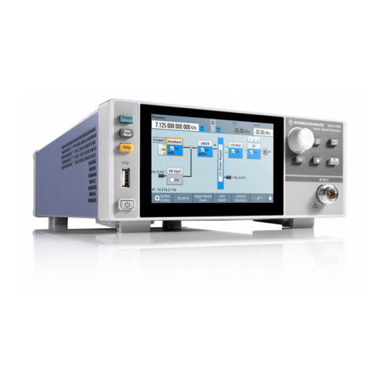
2. Disconnect the R&S SMCV100B from the power source. 3.2 Instrument tour This chapter explains the control elements and the connectors of the R&S SMCV100B. The views of the front panel and the rear panel help you to get familiar with the instru- ment and to perform first steps. - Page 34 ® Getting started R&S SMCV100B Instrument tour Figure 3-3: Front panel view On/Standby, page 35 USB, page 37 Utility keys, page 36 Touchscreen, page 34 Rotary knob, page 37 Function keys, page 36 Editing keys, page 36 Connectors, page 37 3.2.1.1...
- Page 35 ® Getting started R&S SMCV100B Instrument tour Figure 3-4: Touchscreen elements 1 = Status bar (frequency and level display) 2 = Block diagram 3 = Taskbar/softkey bar Any user interface elements that react to a click by a mouse pointer also react to a tap on the screen, and vice versa.
- Page 36 Getting started R&S SMCV100B Instrument tour Utility keys The utility keys cause the R&S SMCV100B to return to a defined instrument state and provide information on the instrument and assistance. For more information, refer to Chapter 11, "General instrument functions", on page 430.
-
Page 37: Rear Panel Tour
® Getting started R&S SMCV100B Instrument tour Navigation controls The navigation controls include a rotary knob, navigation keys, and the display keys. They allow you to navigate within the display or within dialog boxes. Rotary knob The rotary knob has several functions: ●... - Page 38 1024x768 pixels or higher. How to: Chapter 3.1.8, "Connecting a monitor", on page 27 RJ-45 connector to connect the R&S SMCV100B to a LAN for remote control, remote operation, and data transfer. How to: Chapter 3.1.7, "Connecting to LAN", on page 26 User Manual 1179.0597.02 ─...
- Page 39 ® Getting started R&S SMCV100B Instrument tour Two female USB (universal serial bus) 3.0 connectors of type A (host USB). They have the same functionality as the USB connectors on the front panel, but provide higher data rates. See "USB"...
-
Page 40: Trying Out The Instrument
– Base unit – Frequency option R&S SMCVB-B103 ● The R&S SMCV100B is connected to the power supply, and started up as descri- bed in Chapter 3.1, "Preparing for use", on page 23. For the first signal generation tasks, you use the internal baseband and reference sig- nal, so you do not need any additional signal source. -
Page 41: Generating An Unmodulated Carrier
"Prerequisites" on page 40. 1. On the R&S SMCV100B front panel, press the Preset key to start out in a defined instrument configuration. 2. Set the frequency: a) On the "Status Bar", tap the "Frequency" field. -
Page 42: Generating A Digitally Modulated Signal
Figure 3-6: Block diagram: Generating an unmodulated signal The 1.955 GHz signal is output at the RF 50 Ω connector at the front panel of the R&S SMCV100B. Connect RF 50 Ω of the R&S SMCV100B to a signal analyzer, for example R&S ® FSW, to display the generated signal. - Page 43 ® Getting started R&S SMCV100B Trying out the instrument Prerequisites ● Minimum configuration as in "Prerequisites" on page 40 ● Option custom digital modulation R&S SMCVB-K199 The initial situation is not the instrument's preset state but rather the configuration described in Chapter 3.3.1, "Generating an unmodulated...
- Page 44 ® Getting started R&S SMCV100B Trying out the instrument The instrument activates automatically "I/Q Mod", uses the internal trigger and clock signals, and generates a WCDMA-3GPP signal, modulated with a QPSK 45° offset modulation. Figure 3-8: Block diagram: Generating a digitally modulated signal 4.
-
Page 45: Triggering The Instrument With An External Signal
3.3.3 Triggering the instrument with an external signal The following configurations are rather theoretical cases, because you rarely use the R&S SMCV100B as a standalone instrument. Usually, the instrument would be con- nected to a device under test (DUT) and/or other measurement equipment. - Page 46 Trying out the instrument To verify the current connector configuration The R&S SMCV100B is equipped with multipurpose bi-directional User connectors. Because the signal direction, input or output, and the signal mapping are configurable, we recommend that you check the current configuration before cabling or further instrument's configurations.
- Page 47 ® Getting started R&S SMCV100B Trying out the instrument The "Global Connectors" dialog displays the current connectors configuration. The settings are configurable, but in this example we use the default mapping. 3. Alternatively, select "Block Diagram > Baseband > Misc > Custom Digital Mod", select the "Trigger In"...
- Page 48 To connect the instrument and the external trigger source 1. Use a suitable cable to connect the external trigger source to the User 2 connector of the R&S SMCV100B. See Figure 3-11.
-
Page 49: Enabling And Configuring A Marker Signal
Other than in the example, the DUT can be the source for the reference signal. Instead of using an external trigger source, the DUT can also send, for example, a frame trigger signal to the R&S SMCV100B. The R&S SMCV100B acts still as the signal source. - Page 50 User 1 connector of the R&S SMCV100B (see Figure 3-10). 3. Use a suitable cable to connect the User 1 connector of the R&S SMCV100B to ® the monitoring instrument, for example an oscilloscope like R&S RTO. See Fig- 3-12.
-
Page 51: Verifying The Generated Signal With The Graphics Display
3.3.5 Verifying the generated signal with the graphics display It is often useful to check the spectra of the configured signals, before you enable the RF output of the instrument. The R&S SMCV100B has a minimum configuration as in "Prerequisites"... - Page 52 ® Getting started R&S SMCV100B Trying out the instrument 2. Select "Source > Baseband". 3. Select "Add" to enable signal display. In the "Summary" tab, you can verify, that "Channel 0" graphic is visible in the table: A new thumbnail (minimized view) indicating the active diagram appears in the "Taskbar".
- Page 53 ® Getting started R&S SMCV100B Trying out the instrument The "Constellation Diagram" displays the 3GPP FDD signal. 5. To retrieve more information, zoom in. In some diagrams you can select "Show Marker" to measure the distance, for example, between two signals.
-
Page 54: Saving And Recalling Settings
® Getting started R&S SMCV100B Trying out the instrument See also Chapter 9, "Monitoring signal characteristics", on page 380. 3.3.6 Saving and recalling settings To restore the results of our measurements later, we save the instrument settings to a file. - Page 55 ® Getting started R&S SMCV100B Trying out the instrument 4. Tap the "Recall" button. All instrument settings are restored and the display resembles the instrument dis- play right before the settings were saved. To display all parameters with values different to their preset values After loading saved instrument setting, visualize all parameters that have been changed from their default state.
-
Page 56: Generating A Dab Signal
● Option DAB/T-DMB R&S SMCVB-K156 To generate a DAB test signal 1. On the R&S SMCV100B front panel, press the Preset key to start out in a defined instrument configuration. 2. In the block diagram, select "Baseband > T-DMB/DAB". The "T-DMB/DAB" dialog appears and displays the general settings provided for the digital standard. - Page 57 ® Getting started R&S SMCV100B Trying out the instrument As in the user interfaces of all broadcast standards, the "T-DMB/DAB" dialog is divided into several tabs. The "T-DMB/DAB" tab comprises the primary settings of the standard. Also, the functions for storing and recalling settings and provides access to further functions and dialogs.
-
Page 58: System Overview
"DAB Digital Standard for R&S SMCV100B". 3.4 System overview This section helps you to get familiar with the R&S SMCV100B. It provides an introduc- tion to the general concept of the instrument. This section also introduces the main blocks in the signal generation flow. -
Page 59: Signal Flow At A Glance
System overview 3.4.2 Signal flow at a glance The R&S SMCV100B is equipped with a large touchscreen, that displays a block dia- gram. The block diagram represents the signal flow and the general stages the signal generation goes through. Depending on the options the R&S SMCV100B is equipped with, the appearance of the block diagram changes. -
Page 60: Internal Baseband Source ("Baseband" Block)
The "BB Input" and the "I/Q Digital" blocks are the access point to the settings of the digital interfaces Dig. IQ HS x. Equipped with option R&S SMCVB-K19, the R&S SMCV100B is able to receive digital baseband signals and to output digital baseband signals. You can use both interfaces in parallel: Dig. -
Page 61: Additional White Gaussian Noise ("Awgn" Block)
RF frequency and level settings, and the reference frequency, user correction, etc. ● The list and sweep modes 3.4.9 Applications examples of the R&S SMCV100B The R&S SMCV100B can be optimally adapted to the requirements of different appli- cations: ● Generation of digitally modulated signals using –... -
Page 62: Instrument Control
● Generation of signals with up to 240 MHz signal bandwidth (R&S SMCVB-K523) 3.5 Instrument control This chapter provides an overview on how to work with the R&S SMCV100B. It covers the following topics: ● Possible ways to operate the instrument.............. -
Page 63: Understanding The Display Information
● Using a key on the instrument or on a keyboard 3.5.3 Understanding the display information The block diagram of the R&S SMCV100B displays all main settings and generator states, divided into three main operation areas. Figure 3-13: Block diagram... - Page 64 ® Getting started R&S SMCV100B Instrument control 1 = Status bar (frequency and level display) 2 = Block diagram 3 = Taskbar/softkey bar ● Status bar........................64 ● Block diagram......................64 ● Taskbar........................65 ● Additional display characteristics................66 3.5.3.1 Status bar The status bar at the top of the screen indicates the RF frequency and the level of the output signal provided to the DUT.
- Page 65 ® Getting started R&S SMCV100B Instrument control 1, 10, 11 = Connector icons (digital, RF) 2, 9 = Control signal block = Status indicator = Functional block 5, 6 = Graphics indicator = Signal line (digital) = Signal line (analog) Starting from left up to the "I/Q Mod"...
- Page 66 Info line The "Info line" shows brief status information and error messages. It appears when an event generates a message. If selected, the R&S SMCV100B shows informa- tion on static errors and the error history. User Manual 1179.0597.02 ─ 04...
- Page 67 ® Getting started R&S SMCV100B Instrument control ● Key parameters indicated in tab labels Most dialogs are divided into tabs with logically grouped parameters. The tab label expresses the content and can also contain status indicators or the set value of a key parameter.
-
Page 68: Accessing The Functionality
® Getting started R&S SMCV100B Instrument control 3.5.4 Accessing the functionality All functionalities are provided in dialog boxes as known from computer programs. You can control the instrument intuitively with the touchscreen. This section provides an overview of the accessing methods. -
Page 69: Entering Data
The unit is added to the entry. Tip: For quick unit change, you can enter shortcuts, e.g. for a frequency value 1e8h for 100 MHz. For an overview of shortcuts supported by the R&S SMCV100B, see Chapter A.2, "Unit shortcuts", on page 813. -
Page 70: Getting Information And Help
® Getting started R&S SMCV100B Instrument control If you edit numeric data in tables, the entry field must be in edit mode: Press the rotary knob to activate the edit mode. 3.5.5.2 Entering alphanumeric parameters If a field requires alphanumeric input, you can use the on-screen keyboard to enter let- ters and (special) characters. - Page 71 ® Getting started R&S SMCV100B Instrument control Contents of the help dialog box The help dialog box covers two main areas: ● "Contents" - contains a table of help contents ● "Topic" - contains a specific help topic The help system also provides an "Index" and a "Find" area, and "Zoom" functions that are accessed via the corresponding buttons.
-
Page 72: Remote Control
Thus, remote operation of the instrument is possible. Instrument control from a remote computer To access the basic utility functions of the R&S SMCV100B, perform a right mouse click the block diagram and select "Key Emulation". A key panel to the right of the block diagram gives access to the utility functions provi- ded by the front panel keys. -
Page 73: Configuring Internal Baseband Signals
Overview of the signal generation modes 4 Configuring internal baseband signals The R&S SMCV100B is a vector signal generator with internal signal generation and real-time functionality and with integrated arbitrary waveform generator. The instrument enables you to generate various digital modulation signals in accord- ance with the definitions in the corresponding specifications or with user-definable characteristics. -
Page 74: Accessing The Functions In The Baseband Domain
Accessing the functions in the baseband domain Playing a waveform The R&S SMCV100B is equipped with an arbitrary waveform generator (ARB) used to generate test signals and to process waveform files. Waveforms are files with settings provided for repeatable tests with the same test signal. Irrespectively of the way these waveform files are generated, they are always played from the instrument. -
Page 75: Generating Signals According To Broadcast Standards
244 4.3 Generating signals according to broadcast standards The R&S SMCV100B generates digital signals in accordance with the specifications of the main audio broadcast standards, terrestrial broadcast standards and satellite broadcast standards. Since the signals are digital baseband signals, broadcast standards in this chapter are also denoted digital standards. - Page 76 R&S SMCVB-K166. The option provides functionality to generate signals in accordance with the DTMB (digital terrestrial multimedia broadcast) standard. For details, see the R&S SMCV100B DTMB user manual. DVB-T The digital standard requires an instrument equipped with the DVB-T option R&S SMCVB-K163.
- Page 77 It also provides functionality to generate basic DVB-S2 sig- nals. DVB-S is the first-generation DVB standards for satellite services and complies with specification EN 300 421. For details, see the R&S SMCV100B DVB-S/DVB-S2 user manual. DVB-S2 The digital standard requires an instrument equipped with the following options: ●...
-
Page 78: Common Functions And Settings In The Baseband Domain
The option provides functionality to generate digital audio broadcast signals, such as AM signals, FM mono signals and FM stereo signals. FM stereo signals require the RDS (radio data system) coder. For details, see the R&S SMCV100B AM/FM/RDS user manual. 4.4 Common functions and settings in the baseband domain Basic signal generation settings that are common to many generation tasks, regardless of the selected baseband source or digital standard, are described here. - Page 79 Chapter 11.2, "Configuring global connectors", on page 434. Internal modulation data The R&S SMCV100B uses the following internal modulation data sources: ● Data lists Data lists are externally or internally created binary lists with modulation data. The instrument provides standard file select function for loading of existing data lists, creating internally new data lists or editing an existing one.
- Page 80 103 ● Chapter 11.2, "Configuring global connectors", on page 434 Control signals The following control signals are processed in the R&S SMCV100B: ● "Burst Gate" for power ramping ● "Level Attenuation" for power ramping ● "CW/Mod" for controlling the CW (continuous wave) mode...
- Page 81 The "CW" signal turns off digital modulation. The signal is output in unmodulated form. Power ramping and level attenuation The R&S SMCV100B uses the two control signals "Burst Gate" and "Lev_Att" to trigger the power ramping and level attenuation functions.
-
Page 82: Regular Marker Output Signals
4.4.1.2 Regular marker output signals The R&S SMCV100B can add additional signals to the generated signal. Marker sig- nals (or markers) are digital signals which can be used to synchronize external devices to the generated data stream. For example, with suitable marker settings, a slot clock or frame clock can be selected, or the start of a particular modulation symbol can be marked. - Page 83 ® Configuring internal baseband signals R&S SMCV100B Common functions and settings in the baseband domain Related settings: ● Chapter 4.4.2.2, "Marker settings", on page 102 ● Chapter 11.2, "Configuring global connectors", on page 434 ● Marker settings in the dialogs of the firmware options...
-
Page 84: Baseband Trigger Signals
Marker mode CList The instrument generates a marker signal that is defined in the selected control list. The R&S SMCV100B provides a graphical interface for convenient definition of control signals among others also for the marker signals. Delaying marker signals In all the examples listed in "Marker modes"... - Page 85 ® Configuring internal baseband signals R&S SMCV100B Common functions and settings in the baseband domain For information on the trigger signals used in the RF domain, see Chapter 8.9.1, "Sig- nal generation and triggering in the sweep and list modes", on page 318.
- Page 86 ® Configuring internal baseband signals R&S SMCV100B Common functions and settings in the baseband domain Table 4-2: Impact of the trigger events on the generated signal "Trigger Mode" Signal generation 1st Trigger event Subsequent trigger event Trigger event mode "Exec. Trigger" or "Exec.
- Page 87 ® Configuring internal baseband signals R&S SMCV100B Common functions and settings in the baseband domain Figure 4-4: Trigger mode single * = Internal trigger event (to simplify the description) ** = The signal is generated once to the length specified with "Trigger Signal Duration"...
- Page 88 ® Configuring internal baseband signals R&S SMCV100B Common functions and settings in the baseband domain Figure 4-6: Trigger mode retrigger * = Internal trigger event (to simplify the description) Compare the shape and the length of the red curve in single mode and in retrigger mode.
- Page 89 Figure 4-8: Trigger mode armed retrigger * = Internal trigger event (to simplify the description) Impact of the additional trigger settings The R&S SMCV100B provides a set of settings to configure the behavior upon receiv- ing of a trigger signal. For example: ●...
- Page 90 ® Configuring internal baseband signals R&S SMCV100B Common functions and settings in the baseband domain Table 4-3: Impact of the parameter Sync. Output to (External) Trigger "Sync. Output to (External) Trigger = On" "Sync. Output to (External) Trigger = Off"...
- Page 91 ® Configuring internal baseband signals R&S SMCV100B Common functions and settings in the baseband domain Figure 4-9: Trigger delay and trigger inhibit in trigger mode retrigger Specifying delay and inhibit values Trigger delay and inhibit values are expressed in the units of the generated signal, e.g.
-
Page 92: Supported Modulation Signals
45. 4.4.1.4 Supported modulation signals The R&S SMCV100B supports a range of predefined digital and analog modulation signals. All related signals are baseband signals and digitally modulated onto the ana- log RF carrier. In communication techniques, commonly used digital modulation schemes are based on keying. -
Page 93: Supported Coding Schemes
Also, the tool sup- ports the creation of nearly any arbitrarily chosen constellation diagram. The output of "mapwiz" is a mapping file (*.vam) that can be imported into a R&S SMCV100B. The program was developed on a 32-bit Microsoft Windows platform under MATLAB. -
Page 94: Supported Baseband Filters
The filter wizard (filtwiz) is a tool from Rohde & Schwarz designed for creating filter files that can be imported on a R&S SMCV100B. Its main purpose is the conversion of user-defined finite impulse response (FIR) filters into the filter format (*.vaf). Beyond this filtwiz provides designs for standard filters, e.g. - Page 95 ® Configuring internal baseband signals R&S SMCV100B Common functions and settings in the baseband domain the entire bandwidth of the desired signal is allowed to pass and adjust the filter form to reach the spectrum mask requirements. Cut Off Frequency The cut-off frequency or corner frequency is a filter characteristic that defines the fre- quency at the 3 dB down point.
-
Page 96: Methods For Optimizing The Crest Factor
Both effects increase the adjacent-channel power. Direct approaches At the individual signal generation stages, the R&S SMCV100B offers different direct approaches aimed to reduce the crest factor. While the corresponding parameters are enabled, the implemented algorithms ensure minimizing the crest factor or achieving of predefined target crest factor by applying of automatic settings. - Page 97 ® Configuring internal baseband signals R&S SMCV100B Common functions and settings in the baseband domain The provided crest factor reduction methods include: ● Internal calculation of optimized carrier phases for the individual carriers in a multi carrier signal ● Automatic calculation of the carrier start phases in a multi-carrier continuous wave...
-
Page 98: Common Settings
® Configuring internal baseband signals R&S SMCV100B Common functions and settings in the baseband domain Example: The following figures demonstrate the effect of the clipping on the crest factor for typi- cal scenarios. Enabled is clipping with vector mode (|I+q|), using a signal configuration with 2 active channels. - Page 99 ® Configuring internal baseband signals R&S SMCV100B Common functions and settings in the baseband domain Routing and enabling a trigger Use the Global connector settings to configure the signal mapping, the polarity, the trig- ger threshold and the input impedance of the input connectors.
- Page 100 ® Configuring internal baseband signals R&S SMCV100B Common functions and settings in the baseband domain Remote command: on page 629 [:SOURce<hw>]:BB:DM[:TRIGger]:SEQuence on page 677 [:SOURce<hw>]:BB:ARBitrary[:TRIGger]:SEQuence Signal Duration Enters the length of the signal sequence to be output in the "Single" trigger mode.
- Page 101 ® Configuring internal baseband signals R&S SMCV100B Common functions and settings in the baseband domain Remote command: on page 629 [:SOURce<hw>]:BB:DM:TRIGger:SOURce on page 677 [:SOURce<hw>]:BB:ARBitrary:TRIGger:SOURce Sync. Output to External Trigger/Sync. Output to Trigger Enables signal output synchronous to the trigger event.
- Page 102 ® Configuring internal baseband signals R&S SMCV100B Common functions and settings in the baseband domain ● "Specifying delay and inhibit values" on page 91 The parameter Actual Trigger Delay/Actual External Delay displays the delay conver- ted in time. Remote command: on page 631 [:SOURce<hw>]:BB:DM:TRIGger[:EXTernal]:DELay...
- Page 103 ® Configuring internal baseband signals R&S SMCV100B Common functions and settings in the baseband domain The instrument routes the generated marker signals to the selected output connectors. See also Chapter 11.2, "Configuring global connectors", on page 434. "CList" A marker signal as defined in the selected control list.
-
Page 104: Generating Custom Digital Modulated Signals
An inappropriate change of a parameter triggers a settings conflict, which is indicated by a message on the "Info" line in the display. Although the R&S SMCV100B displays User Manual 1179.0597.02 ─ 04... -
Page 105: Custom Digital Modulation Settings
® Configuring internal baseband signals R&S SMCV100B Generating custom digital modulated signals the selected settings, the generated modulation signal does not correspond to this dis- play. The displayed message disappears when a conflict-free setting is selected. Refer to Chapter 14, "Troubleshooting and notifications",... - Page 106 ® Configuring internal baseband signals R&S SMCV100B Generating custom digital modulated signals Settings: State..........................106 Set To Default......................106 Save/Recall......................... 106 Set according to Standard...................107 Symbol Rate........................107 Coding.........................107 Power Ramp Control....................107 State Enables/disables digital modulation. Switching on digital modulation turns off all other digital standards.
- Page 107 ® Configuring internal baseband signals R&S SMCV100B Generating custom digital modulated signals Remote command: on page 621 [:SOURce<hw>]:BB:DM:SETTing:CATalog? on page 622 [:SOURce<hw>]:BB:DM:SETTing:DELete on page 622 [:SOURce<hw>]:BB:DM:SETTing:LOAD on page 621 [:SOURce<hw>]:BB:DM:SETTing:STORe Set according to Standard Selects a predefined communication standard. "Predefined communication standard"...
-
Page 108: Trigger, Marker And Clock Setting
® Configuring internal baseband signals R&S SMCV100B Generating custom digital modulated signals 4.5.3.2 Trigger, marker and clock setting These tabs provide standard settings. For detailed description, see: ● Chapter 4.4.2.1, "Trigger settings", on page 99 ● Chapter 4.4.2.2, "Marker settings", on page 102 ●... - Page 109 ® Configuring internal baseband signals R&S SMCV100B Generating custom digital modulated signals "Pattern" Use the "Pattern" box to define a bit pattern with a maximum length of 64 bits. Remote command: on page 620 [:SOURce<hw>]:BB:DM:PATTern "Data List" Binary data from data lists are used, see Select Data List.
-
Page 110: Modulation Settings
® Configuring internal baseband signals R&S SMCV100B Generating custom digital modulated signals Connector Settings Accesses the connectors settings. See also Chapter 11.2, "Configuring global connectors", on page 434. 4.5.3.4 Modulation settings Access: ► Select "Baseband > Custom Digital Mod > Modulation". - Page 111 ® Configuring internal baseband signals R&S SMCV100B Generating custom digital modulated signals Remote command: on page 625 [:SOURce<hw>]:BB:DM:FORMat Load User Mapping Accesses the "Select List File User Mapping" dialog to select the mapping table (see "User mapping" on page 93). The dialog provides all standard file management func- tions.
-
Page 112: Filter Settings
® Configuring internal baseband signals R&S SMCV100B Generating custom digital modulated signals Remote command: on page 626 [:SOURce<hw>]:BB:DM:FSK:VARiable:TYPE Deviation xxxx For "Variable FSK", sets the deviation of the associated symbol. The number of sym- bols depends on the selected modulation type. The value of each symbol is indicated in binary format, i.e. - Page 113 ® Configuring internal baseband signals R&S SMCV100B Generating custom digital modulated signals Settings: Filter..........................113 Filter Parameter......................113 Cutoff Frequency Factor....................113 Bandwidth........................113 Load User Filter......................113 Filter Selects the baseband filter. Refer to Chapter 4.5.5.2, "Predefined baseband filters", on page 130 for an overview of the available filter types, their filter shapes and filter parameters.
-
Page 114: Power Ramp Control Settings
® Configuring internal baseband signals R&S SMCV100B Generating custom digital modulated signals Remote command: on page 635 [:SOURce<hw>]:BB:DM:FLISt:SELect on page 635 [:SOURce<hw>]:BB:DM:FLISt:CATalog? on page 636 [:SOURce<hw>]:BB:DM:FLISt:DELete 4.5.3.6 Power ramp control settings Access: ► Select "Baseband > Custom Digital Modulation > General > Power Ramp Control". - Page 115 ® Configuring internal baseband signals R&S SMCV100B Generating custom digital modulated signals Remote command: on page 629 [:SOURce<hw>]:BB:DM:PRAMp[:STATe] Source Defines the source for the power ramp control signals. "Internal" The control signals as defined in the internal control list are used for control purposes.
-
Page 116: Data List Editor
629 [:SOURce<hw>]:BB:DM:PRAMp:BBONly[:STATe] 4.5.3.7 Data list editor The R&S SMCV100B provides the following ways to create a data list file: ● To use the dedicated "Data List Editor" and create a file with extension *.dm_iqd, "To create data lists manually"... - Page 117 ® Configuring internal baseband signals R&S SMCV100B Generating custom digital modulated signals For example, in the directory /var/user/, enter "Filename" = dl_3gpp The "Data List Editor" is a list of binary values with a maximum length of 2 bits. This value corresponds to a file size of approx. 268 Mbyte.
-
Page 118: Control And Marker Lists Editor
Saves the changes into the selected data list file. 4.5.3.8 Control and marker lists editor The R&S SMCV100B provides the following ways to create a file containing control signals: ● To use the tag-oriented format and create a control list file, see "To create a control... - Page 119 ® Configuring internal baseband signals R&S SMCV100B Generating custom digital modulated signals 5. Select "Edit". The dedicated internal "Control Data Editor" is an intuitive graphical interface provi- ded for defining and managing of: ● Marker signals ● Control signals, like the CW, "Hop", "Burst Gate", and "Lev_Att" control signals (see also "Control signals"...
- Page 120 ® Configuring internal baseband signals R&S SMCV100B Generating custom digital modulated signals Positions Control Signal....................121 Zoom/Visible........................121 Save/Save As......................121 Configure Control Signal Displays the color the marker/control signal has been assigned. The status checkbox indicates whether the individual marker or control signal is assigned or enabled (see Chapter 4.5.4.1, "How to create and assign a control...
- Page 121 ® Configuring internal baseband signals R&S SMCV100B Generating custom digital modulated signals Remote command: n.a. Cursor Position Displays/enters the cursor position in the graphical display If the entered value exceeds the selected length of the definition range, the length is adjusted automatically.
-
Page 122: How To Create Data And Control Lists
105. 4.5.4.1 How to create and assign a control list The R&S SMCV100B provides the following ways to create a file containing control signals: ● To use the dedicated Control and marker lists editor and create a file in ASCII for- mat and with extension *.dm_iqc, see... - Page 123 To use a marker/control signal from a control list and to output this signal at the suppor- ted connector, perform the following: ► Enable the R&S SMCV100B to use the control list for marker output 2. Output this signal at the User2 connector: a) Select "Baseband >...
- Page 124 Irrespectively on the way they are created, generated data lists are not automatically used. ► To enable the R&S SMCV100B to use the data list as data source for the custom digital modulation: a) Select "Baseband > Custom Digital Modulation > Data Source > Data List"...
-
Page 125: References
® Configuring internal baseband signals R&S SMCV100B Generating custom digital modulated signals 4.5.5 References Table 4-4: Custom digital modulation default values Parameter Value "State" Not affected "Data Source" "PRBS 9" "Standard" "GSM" "Symbol Rate" "270.833 ksymb/s" "Coding" "GSM" "Modulation Type"... - Page 126 ® Configuring internal baseband signals R&S SMCV100B Generating custom digital modulated signals Standard Modulation Symbol rate Filter Coding Parameter for SCPI command APCO Phase1 pi/4-DQPSK 4.8 ksym/s APCO25 (LSM), Gauss APCO25(PSK) APCOPH1Lsm Cut Off = 2.04 kHz, Low- pass Cut Off = 6.2 kHz...
- Page 127 ® Configuring internal baseband signals R&S SMCV100B Generating custom digital modulated signals Differ- Phase Diff.+ Gray NADC, TFTS/ INMARSAT, APCO2 APCO25 ential Diff. Gray PDC, TETR ICO, 5 (FSK) (8PSK) PHS, WCDMA, TETRA, cdma2000 APCO25 (PSK), QPSK45° Off- Pi/4 QPSK...
- Page 128 ® Configuring internal baseband signals R&S SMCV100B Generating custom digital modulated signals 4.5.5.1 Common coding algorithms In the notation used below, a denotes the n input symbol and b denotes the corre- spondingly coded output symbol. Individual bits in the symbols from the LSB (least sig- nificant bit) to the MSB (most significant bit) are denoted by a , etc.
- Page 129 ® Configuring internal baseband signals R&S SMCV100B Generating custom digital modulated signals Example: Differential coding for QPSK modulation with K = 2 bit/symbol Decimal display; the value range for modulation symbols is a = {0, 1, 2, 3} According to...
- Page 130 ® Configuring internal baseband signals R&S SMCV100B Generating custom digital modulated signals 4.5.5.2 Predefined baseband filters Table 4-11 shows the filters that are available, together with their associated parameters. The filter characteristic is displayed in graphical form. Filter names "Cosine" and "Root Cosine"...
- Page 131 ® Configuring internal baseband signals R&S SMCV100B Generating custom digital modulated signals "Gauss Linearized" "Edge Narrow Pulse Shape" "Edge Wide Pulse Shape" "cdmaOne" User Manual 1179.0597.02 ─ 04...
- Page 132 ® Configuring internal baseband signals R&S SMCV100B Generating custom digital modulated signals "cdmaOne 705kHz" "cdmaOne + Equalizer" "cdmaOne 705kHz + Equalizer" "cdma2000 3X" User Manual 1179.0597.02 ─ 04...
- Page 133 ® Configuring internal baseband signals R&S SMCV100B Generating custom digital modulated signals "APCO25" "APCO25 (H-CPM)" "Roll Off Factor" "APCO25 (LSM)" "Split Phase" "Gauss Cut Off Frequency" "B*T" "Lowpass Cut Off Frequency" User Manual 1179.0597.02 ─ 04...
- Page 134 ® Configuring internal baseband signals R&S SMCV100B Generating custom digital modulated signals "Rectangular" "Dirac" "Lowpass (ACP optim.)" "Lowpass (EVM optim.)" User Manual 1179.0597.02 ─ 04...
-
Page 135: Using The Arbitrary Waveform Generator (Arb)
The arbitrary waveform generator (ARB) is an I/Q modulation source forming part of the R&S SMCV100B. The ARB allows the playback and output of any externally calcu- lated modulation signals in the form of waveform files. The ARB can also generate multi-carrier or multi-segment signals from the waveform files. -
Page 136: Required Options
4.6.2.1 Waveform files sources In ARB mode, the R&S SMCV100B uses ARB waveform files to obtain the digital I/Q data of the baseband signal. The R&S SMCV100B can play back any waveform file saved on a network drive but it can also generate and play back simple waveforms for test purposes. - Page 137 *.wv. When waveforms are created by the R&S SMCV100B, the instrument inserts a wave- form header at the beginning of each created ARB file. The header of the generated I/Q data files consists of "tags"...
- Page 138 Play back from the internal memory In the most common case, the ARB generator plays back a waveform file with a selectable clock frequency. The R&S SMCV100B loads the entire file into the ARB memory from where the IQ samples are played repeatedly.
- Page 139 ® Configuring internal baseband signals R&S SMCV100B Using the arbitrary waveform generator (ARB) The first sine signal is mapped on the I samples, the second on the Q samples. The two signals differ by a selectable phase offset. For a –90 deg offset, the result is a unit vector in the I/Q plane, rotating counter-clockwise and starting at I = 0, Q = –1.
- Page 140 ® Configuring internal baseband signals R&S SMCV100B Using the arbitrary waveform generator (ARB) 4.6.2.4 Waveform sample rate The Arbitrary Waveform Generator includes a resampling unit that interpolates the input samples to reach a target digital output I/Q sample rate. The input sample rate...
-
Page 141: Arb Settings
4.6.2.5 Impact of enabled number of marker signals on waveform length The R&S SMCV100B provides the possibility to define marker signals, that are sent to the marker outputs in synchronicity with the I/Q output signals. Marker signals can be either predefined or later defined. -
Page 142: Arb General Settings
® Configuring internal baseband signals R&S SMCV100B Using the arbitrary waveform generator (ARB) The "ARB" dialog enables direct selection of the waveform file to be processed, the selection of a test signal or access to the multi-segment and multi-carrier settings. - Page 143 ® Configuring internal baseband signals R&S SMCV100B Using the arbitrary waveform generator (ARB) Segment Trigger In" in the "Trigger" tab; for information see Chapter 4.8.3.5, "Multi- segment waveform trigger settings", on page 207. Settings: State..........................143 Set To Default......................143 Load Waveform/File....................144 Waveform Info......................
- Page 144 ® Configuring internal baseband signals R&S SMCV100B Using the arbitrary waveform generator (ARB) Remote command: on page 649 [:SOURce<hw>]:BB:ARBitrary:PRESet Load Waveform/File Accesses the standard "File Select" function of the instrument. The provided navigation possibilities in the dialog are self-explanatory. The waveform files are files with predefined file extension *.wv. When a file is selected, the dialog displays short information about the selected waveform.
- Page 145 ® Configuring internal baseband signals R&S SMCV100B Using the arbitrary waveform generator (ARB) Activates ARB waveform streaming from a mass memory. The internal solid-state drive or an external mass memory (HDD, USB flash memory) can provide as memory. Connect the external memory to one of the USB connectors. We recommend that you connect to the USB 3.0 connectors on the rear panel, to provide sufficient streaming...
-
Page 146: Sine Test Signals
® Configuring internal baseband signals R&S SMCV100B Using the arbitrary waveform generator (ARB) 4.6.3.2 Sine test signals Access: ► Select "Baseband > ARB > General > Test Signal Form > Sine" and press "Create Test Signal". This dialog provides settings for configuration of a sinusoidal test signal. A sine wave is generated on the I path, and a sine wave of the same frequency but phase-shifted is generated on the Q path. -
Page 147: Rectangular Test Signal
® Configuring internal baseband signals R&S SMCV100B Using the arbitrary waveform generator (ARB) Phase Offset Q Enters the phase offset of the sine-wave signal on the Q channel relative to the sine- wave signal on the I channel. Remote command: on page 652 [:SOURce<hw>]:BB:ARBitrary:TSIGnal:SINE:PHASe... - Page 148 ® Configuring internal baseband signals R&S SMCV100B Using the arbitrary waveform generator (ARB) Settings: Frequency........................148 Samples per Period.....................148 Amplitude........................148 Offset DC........................148 Generate Signal File....................148 Generate Signal RAM....................148 Frequency Enters the frequency of the test signal. Remote command: on page 651 [:SOURce<hw>]:BB:ARBitrary:TSIGnal:RECTangle:FREQuency...
-
Page 149: Constant Iq Test Signal
® Configuring internal baseband signals R&S SMCV100B Using the arbitrary waveform generator (ARB) 4.6.3.4 Constant IQ test signal Access: 1. Select "Baseband > ARB > General > Test Signal Form > Const IQ". 2. Select "Create Test Signal". This dialog provides settings for configuration of a continuous test signal with con- stant IQ. -
Page 150: Trigger, Marker And Clock Settings
® Configuring internal baseband signals R&S SMCV100B Using the arbitrary waveform generator (ARB) 4.6.3.5 Trigger, marker and clock settings These tabs provide standard settings. For detailed description, see: ● Chapter 4.4.2.1, "Trigger settings", on page 99 ● Chapter 4.4.2.2, "Marker settings",... -
Page 151: How To Create, Generate And Play Waveform Files
157. Provided the R&S SMCV100B is equipped with the required option, you can load this waveform file and subsequent process it with the instrument. This section provides examples on the internal waveform file generation and on the external generation with the R&S WinIQSIM2. - Page 152 How to use waveform files with R&S WinIQSIM2 The following is an example on how to use R&S WinIQSIM2 to generate an EUTRA/LTE waveform and load it in the ARB of the R&S SMCV100B. The workflow consists of three main steps, each described in a separate step-by-step instruction: ●...
- Page 153 4. Close the dialog. 5. In the block diagram, select "Vector Sig Gen" block and select the R&S SMCV100B form the list. 6. In the block diagram, select "ARB Sig Gen" block and select the R&S SMCV100B form the list.
- Page 154 ® Configuring internal baseband signals R&S SMCV100B Using the arbitrary waveform generator (ARB) To generate a waveform file with R&S WinIQSIM2 1. In the block diagram of R&S WinIQSIM2, select "Baseband > EUTRA/LTE/IoT". 2. Adjust the settings as required, for example: a) Select "Link Direction >...
- Page 155 ® Configuring internal baseband signals R&S SMCV100B Using the arbitrary waveform generator (ARB) User Manual 1179.0597.02 ─ 04...
- Page 156 The display confirms the expected EUTRA/LTE 10 MHz spectrum. To transfer the waveform file to the R&S SMCV100B 1. In the R&S WinIQSIM2, select "Transmission > Transmit". 2. In the "Waveform Transmission to Arbitrary Waveform Generator" dialog, select: a) "Transmit from >...
- Page 157 SMCV100B Using the arbitrary waveform generator (ARB) The waveform is transmitted to the default directory of the R&S SMCV100B. 3. In the R&S SMCV100B, select "Baseband > ARB". The dialog confirms that the ARB is enabled and plays the transmitted waveform.
- Page 158 ® Configuring internal baseband signals R&S SMCV100B Using the arbitrary waveform generator (ARB) Figure 4-13: Principle of creating a waveform manually The following steps outline how to create the waveform file SICO.wv: 1. Calculate the sine and cosine values, e.g. use the SICO.cpp program.
- Page 159 ® Configuring internal baseband signals R&S SMCV100B Using the arbitrary waveform generator (ARB) Figure 4-15 shows the calculation and conversion steps. The highlighted col- umns contain the resulting I and Q values represented in Little endian format. Figure 4-15: I and Q values calculation and conversion 3.
- Page 160 ® Configuring internal baseband signals R&S SMCV100B Using the arbitrary waveform generator (ARB) Note: There is no readable representation for binary values in this document. This is why we use the sequence I0Q0I1Q1...InQn to characterize the binary code in the present example.
- Page 161 ® Configuring internal baseband signals R&S SMCV100B Using the arbitrary waveform generator (ARB) // SICO.wv // Generating a binary data set from the I/Q pairs in the file SICO.txt // and storing the result to file SICO.wv FILE *fp_sour, *fp_dest;...
- Page 162 ® Configuring internal baseband signals R&S SMCV100B Using the arbitrary waveform generator (ARB) To define periodical marker trace The waveform in the example on Figure 4-16 consists of 3 frames, each frame is 100- samples long. The waveform is processed continuously ("Trigger Mode > Auto").
- Page 163 150 samples. 4.6.4.6 How to create a control list using tag file format The R&S SMCV100B provides the following ways to create a file containing control signals: ● to use the dedicated "Control Data Editor" and create a file in ASCII format and with extension *.dm_iqc, see...
- Page 164 ® Configuring internal baseband signals R&S SMCV100B Using the arbitrary waveform generator (ARB) They can be inserted after the TYPE tag in arbitrary order. An example of the control list file contents could be: {TYPE:SMU-CL}{COPYRIGHT:Rohde&Schwarz} {DATE:2012-06-11;15:00:09}{HOP LIST:0:0;498:1;506:0} {CW MODE LIST:0:0;380:1}{LEVATT LIST 3:0:0;464:1} {BURST LIST:0:0;122:1;270:0;582:1;924:0}...
- Page 165 :SOURce1:BB:DM:PRAMp:SOURce INTernal 4.6.4.7 How to create a data list using tag file format The R&S SMCV100B provides the following ways to create a data list file: ● To use the dedicated "Data List Editor" and create a file with extension *.dm_iqd, "To create data lists manually"...
- Page 166 We assume, that a data list dl.dm_iqd is created and saved in the direc- tory /var/user/. The following example shows how to enable the R&S SMCV100B to use this data list as data source for the custom digital modulation. MMEM:CDIRectory "/var/user"...
-
Page 167: How To Work With Waveform Libraries
SMCV100B Using the arbitrary waveform generator (ARB) 4.6.5 How to work with waveform libraries The R&S SMCV100B offers waveform libraries containing waveform files (*.wv) with a wide range of ready-made signals for testing systems with different transmission parameters. Key features ●... - Page 168 3. After product registration, log in at GLORIS. 4. In the menu bar, select "Support&Services > My Products > Vector Signal Genera- tor Customer Web". The "R&S SMCV100B Customer Web" page opens. ® 5. In the selection field "Product Selection for VSG", select "R&S SMCV100B".
- Page 169 Using the arbitrary waveform generator (ARB) 1. Access the "Product Related Documents" web page as described in "To access R&S SMCV100B libraries" on page 167. 2. In the search navigation bar, select "Firm-/Software" > "Waveform & Streams". The search lists all information related to stream and waveform libraries of the R&S SMCV100B:...
-
Page 170: How To Stream Waveforms From An External Storage Device
Required options Chapter 4.6.1, "Required options", on page 136. The following procedures help you to set up the R&S SMCV100B for ARB waveform streaming. To set up and connect the external waveform source 1. Provide an HDD as waveform streaming source. -
Page 171: Tags For Waveforms, Data And Control Lists
50 Ω connector. 4.6.7 Tags for waveforms, data and control lists The R&S SMCV100B uses a simple tag-oriented format for externally or internally gen- erated waveforms, data and control lists. Files with this format can be transmitted from an external computer to the instrument and vice versa. These files are transmitted as a binary data block, using SCPI command [:SOURce<hw>]:BB:ARBitrary:... - Page 172 For each tag, an indication shows whether it must be included in the file concerned (mandatory) or may be included (optional). Unknown tags are not analyzed by the R&S SMCV100B; they are left unchanged and saved without an error message for a possible further read back.
- Page 173 (mandatory, must be the first tag in the file) Identifies the file as a valid R&S SMCV100B file. It must be present and must be the first in the waveform. If a file of the same name exists on the target medium, it is over- written.
- Page 174 The tag contains a plain text ASCII string of arbitrary length. The string is not analyzed in the R&S SMCV100B. It is used to describe the file. The string is allowed to contain all printable ASCII characters except the closing curly bracket.
-
Page 175: Clock: Frequency
® Configuring internal baseband signals R&S SMCV100B Using the arbitrary waveform generator (ARB) Usage: Setting only 4.6.7.2 Tags for single and multi-segment waveforms The following tags apply to waveforms and multi-segment wavefroms, additionally to the tags listed in Chapter 4.6.7.1, "Common tags",... -
Page 176: Control Length: Controllength
® Configuring internal baseband signals R&S SMCV100B Using the arbitrary waveform generator (ARB) Example: {CLOCK: 54000000} BB:ARB:WAV:TAG? 'CLOCK' Queries the content of the CLOCK tag. Response: 54000000 The clock frequency is set to 54 MHz. Usage: Setting only {CONTROL LENGTH: ControlLength} (optional / recommended for marker and control lists) The tag specifies the length of all control or marker list in ASCII format. -
Page 177: Emptytag-Length: #Emptysequence
® Configuring internal baseband signals R&S SMCV100B Using the arbitrary waveform generator (ARB) {EMPTYTAG-Length: #EmptySequence} (mandatory in automatically generated one and multi-segment waveforms) This tag is empty, i.e. contains no data, and is used as placeholder. Setting parameters: Length An ASCII integer value that specifies the number of bytes in the EMPTYTAG, i.e. -
Page 178: Marker Mode [#]: Generator
® Configuring internal baseband signals R&S SMCV100B Using the arbitrary waveform generator (ARB) Setting parameters: RMSOffset_dB Defines the RMS level offset of the signal relative to full scale ARB signal in the WAVEFORM tag. The offset is defined in ASCII float format. -
Page 179: Samples: Samples
® Configuring internal baseband signals R&S SMCV100B Using the arbitrary waveform generator (ARB) The marker signals defined with the tag are processed internally; MARKER LIST additional control list is not created. If the tag is used for all 3 markers, the whole ARB memory is available for the I/Q samples. -
Page 180: Waveform-Length: #I0Q0I1Q1
® Configuring internal baseband signals R&S SMCV100B Using the arbitrary waveform generator (ARB) Setting parameters: [TRACE] MARKER | BURST | LEVATT | CW MODE | HOP | MAP Name of the marker or control signal. For ARB waveforms, it is only meaningful to define marker sig- nals;... -
Page 181: Mwv_Segment_Count: Numofseg
® Configuring internal baseband signals R&S SMCV100B Using the arbitrary waveform generator (ARB) Setting parameters: Length Specifies the number of bytes in a WAVEFORM tag and is calcula- ted as follows: Length = Number of I/Q pairs * 4 (2 bytes per I and 2... -
Page 182: Mwv_Segment_Duration: Segdur0, Segdur1
® Configuring internal baseband signals R&S SMCV100B Using the arbitrary waveform generator (ARB) {MWV_SEGMENT_DURATION: SegDur0, SegDur1, …, SegDurN-1} (optional for multi-segment waveforms) The tag gives the time duration (in seconds) per segment. Example: {MWV_SEGMENT_DURATION: 1,0.5} Multi-segment waveform with 2 segments, lasting 1 s and 0.5 s each. -
Page 183: Mwv_Segment_Clock: Clockseg0, Clockseg1
® Configuring internal baseband signals R&S SMCV100B Using the arbitrary waveform generator (ARB) The tag CLOCK contains always the highest clock rate of all segments. The tag MWV_SEGMENT_CLOCK contains the clock rates of the individual segments. Setting parameters: Mode UNCHANGED The segments may have different clock rates;... -
Page 184: Mwv_Segment_Level_Offs
® Configuring internal baseband signals R&S SMCV100B Using the arbitrary waveform generator (ARB) EQUALRMS Segments are output so that all segments have the same RMS value. The value displayed with the parameter "Task bar > Level" applies to all segments. -
Page 185: Mwv_Segmentx_Comment: Text
® Configuring internal baseband signals R&S SMCV100B Using the arbitrary waveform generator (ARB) {MWV_SEGMENTx_COMMENT: text} (optional for multi-segment waveforms) The tag contains a user comment for a specific segment x = [0…NumOfSeg-1] in the multi-segment waveform in ASCII format. Example: {MWV_SEGMENT1_FILES: segment 1 contains a QPSK signal.}... - Page 186 ® Configuring internal baseband signals R&S SMCV100B Using the arbitrary waveform generator (ARB) 4.6.7.3 Tags for data lists The following tags apply to data lists, additionally to the tags listed in Chapter 4.6.7.1, "Common tags", on page 173..................186 {DATA BITLENGTH: BitLength} .................
- Page 187 ® Configuring internal baseband signals R&S SMCV100B Using the arbitrary waveform generator (ARB) ........... 188 {MAP LIST [#]: Pos0:State0; Pos1:State1; ...PosN-1:StateN-1} ........188 {MARKER LIST [#]: Pos0:State0; Pos1:State1; ...PosN-1:StateN-1} ........188 {[TRACE] LIST [#]: Pos0:State0; Pos1:State1; ...PosN-1:StateN-1} {CONTROL LENGTH: ControlLength} (optional / recommended for marker and control lists) The tag specifies the length of all control or marker list in ASCII format.
- Page 188 ® Configuring internal baseband signals R&S SMCV100B Using the arbitrary waveform generator (ARB) {MAP LIST [#]: Pos0:State0; Pos1:State1; ...PosN-1:StateN-1} {MARKER LIST [#]: Pos0:State0; Pos1:State1; ...PosN-1:StateN-1} {[TRACE] LIST [#]: Pos0:State0; Pos1:State1; ...PosN-1:StateN-1} (mandatory for control lists / optional for waveforms) The tag contains the data for the marker and control signals in the control list or the marker signals of ARB waveforms.
-
Page 189: Reducing The Crest Factor
To fulfill the requirements of these test systems and to enable rapid alternation between different waveforms with differing test signals, the R&S SMCV100B provides the functionality to generate multi-segment waveform files. This section introduces the concept of the multi-segment waveform files, together with description of the provided settings and some typical configuration examples. - Page 190 “Play List”. The R&S SMCV100B provides the possibility to define a sequence of different segments and to determine whether a segment is played once or repeated several times and to adjust the transition between the segments.
- Page 191 4.8.2.3 File concept To provide flexible configuration, the building of a composed multi-segment waveform file involves different stages; by completing of each of them, the R&S SMCV100B cre- ates and stores a dedicated file. The following files are used: ●...
- Page 192 ® Configuring internal baseband signals R&S SMCV100B Generating multi-segment waveform files for one of these purposes overwrites markers that use the same output connector and that are defined in the individual waveforms. Figure 4-24: Example of marker signals The segment begin is defined by the low-high slope of the marker, which applies for switching between two segments and if there is a segment replay.
- Page 193 ® Configuring internal baseband signals R&S SMCV100B Generating multi-segment waveform files Figure 4-26 illustrates how trigger events affect the processing of the multi-seg- ment waveforms. Figure 4-26: Principle of segment triggering = To simplify the description, an internal next segment trigger event ("Exec. Next Segment") and an internal trigger event ("Execute Trigger") are used;...
- Page 194 Configuring internal baseband signals R&S SMCV100B Generating multi-segment waveform files Defining the Transition between the Segments The R&S SMCV100B provides the parameter "Next Segment Mode" to define the tran- sition to the subsequent segment (see the graphs in Transition examples). ●...
-
Page 195: Multi-Segment Settings
® Configuring internal baseband signals R&S SMCV100B Generating multi-segment waveform files ● The triangle on the top line denotes a trigger event. A filled triangle on the bottom line denotes a next segment event. ● A green sine wave (or other shape) over a full period indicates one replay cycle of a segment. - Page 196 ® Configuring internal baseband signals R&S SMCV100B Generating multi-segment waveform files 4. Select "Baseband > ARB > General". The "Load Waveform" confirms that the current multi-segment file is loaded (file- name as defined with "Output File"). Note: The provided settings depend on the current waveform.
- Page 197 ® Configuring internal baseband signals R&S SMCV100B Generating multi-segment waveform files Settings: List........................197 Load List........................197 Save List/Save List As....................197 Sequencing List......................197 Comment........................197 Output file........................198 Create/Create and Load....................198 New List Accesses the standard "Create Multi Segment Waveform List" function to enter the name of the new file.
- Page 198 ● "Create and Load" Creates a multi-segment waveform and loads it in the ARB generator. The R&S SMCV100B stores the multi-carrier waveform as file with filename as speci- fied with parameter Output file. Depending on the configuration of the multi-carrier waveform, calculation takes some time.
- Page 199 ® Configuring internal baseband signals R&S SMCV100B Generating multi-segment waveform files 5. Select "Append Blank" to add a bank segment and configure the "Blank Segment Settings" as required. This section explains the settings, necessary to create and adjust the contents of the multi-segment file.
- Page 200 ® Configuring internal baseband signals R&S SMCV100B Generating multi-segment waveform files "Info" Indication of the possible comment contained in the waveform. Remote command: [:SOURce<hw>]:BB:ARBitrary:WSEGment:CONFigure:SEGMent:CATalog? on page 659 Append/Delete/Shift Seg. Up/Down Standard handling functions: "Append" Opens the standard "File Select" dialog for navigation to and selec- tion of the waveform file to be added on the end of the existing list.
- Page 201 ® Configuring internal baseband signals R&S SMCV100B Generating multi-segment waveform files 2. In the "ARB: Multi Segment > General" dialog, select an existing list. 3. Select "ARB: Multi Segment > Segment Table" and configure the segments. 4. Select "ARB: Multi Segment > Level/Marker/Clock".
- Page 202 ® Configuring internal baseband signals R&S SMCV100B Generating multi-segment waveform files "Highest" All segments are output at the highest available clock rate. Note: Trade-off between fast switch over and computing time. This mode provides short switch over times between segments.
- Page 203 ® Configuring internal baseband signals R&S SMCV100B Generating multi-segment waveform files If additional marker generation is enabled, the existing marker signals in the individual segment waveform files are not considered, see also Chapter 4.8.2.4, "Impact of the marker settings", on page 191.
- Page 204 ® Configuring internal baseband signals R&S SMCV100B Generating multi-segment waveform files The user interface shows the configured play list in form of a "Sequencing Graphic". Refer to "Sequencing play list settings" on page 205 for description of the provided settings.
- Page 205 ® Configuring internal baseband signals R&S SMCV100B Generating multi-segment waveform files Settings: New/Load Sequencing List..................205 Save List/Save List As....................205 Sequencing List......................205 Assigned to Multi Seg. Waveform................205 New/Load Sequencing List Accesses the standard "Select Sequencing List" function to define the name of the new play list file or select of an existing one.
- Page 206 ® Configuring internal baseband signals R&S SMCV100B Generating multi-segment waveform files Settings: Sequencing Play List....................206 └ Next.......................207 └ Append......................207 └ Delete......................207 └ Shift Id# Up/Down..................207 Sequencing Graphic....................207 Sequencing Play List The "Sequencing Play List" table defines the sequence order the waveform file seg- ments are processed and how many times each of them is repeated.
- Page 207 ® Configuring internal baseband signals R&S SMCV100B Generating multi-segment waveform files Remote command: "Append" on page 207 Next ← Sequencing Play List Determines the action after completing the current one, like for instance which seg- ment is processed after the processing of the current one is finished.
- Page 208 ® Configuring internal baseband signals R&S SMCV100B Generating multi-segment waveform files 2. Select "Baseband > ARB > Trigger In (MSW)". The "Next Segment Trigger In" section comprises the settings necessary to adjust the trigger for switching between the segments of a multi-segment waveform. The parameters displayed depend on the selected trigger source.
- Page 209 ® Configuring internal baseband signals R&S SMCV100B Generating multi-segment waveform files Use the parameter Next Segment Mode to define whether the new segment is gener- ated immediately or only after the previous segment has been fully generated (wrap around). The subsequent trigger event after the last segment causes the first segment to be output again.
- Page 210 ® Configuring internal baseband signals R&S SMCV100B Generating multi-segment waveform files Next Segment Source Determines whether the next segment is switched upon receiving of an external trigger signal or upon executing of software next segment trigger (see Figure 4-26). This parameter is disabled, if a sequencing play list is used.
-
Page 211: How To Create And Work With Multi-Segment Waveform Files
® Configuring internal baseband signals R&S SMCV100B Generating multi-segment waveform files 4.8.4 How to create and work with multi-segment waveform files This section provides step-by-step instructions on how to configure and use the multi- segment settings. The Figure 4-27 shows the essential stages of multi-segment wave- form configuration, together with the corresponding user interface dialogs and if appli- cable, the corresponding file extensions. - Page 212 ® Configuring internal baseband signals R&S SMCV100B Generating multi-segment waveform files The following description emphasizes on the settings required to fulfill the particular task or achieve the desired performance; standard basic settings are not discussed. All provided examples use the example segment sequence as shown on Figure 4-28.
- Page 213 ® Configuring internal baseband signals R&S SMCV100B Generating multi-segment waveform files The "ARB > Trigger In (MSW)" settings display the currently output segment: "Cur- rent Segment Name = Seg#0" and "Curent Segment Index = 0". Seg#0 is output continuously. 5. Set "ARB > Trigger In (MSW) > Segment = 3" to output the second segment in the sequence order.
- Page 214 ® Configuring internal baseband signals R&S SMCV100B Generating multi-segment waveform files 4. A segment ("Current Segment") is output continuously as long as the value of the parameter "Segment" is not changed. Change the value of the parameter "ARB > Trigger In (MSW) > Segment" to select the segment index processed after com- pleting the current one.
- Page 215 ® Configuring internal baseband signals R&S SMCV100B Generating multi-segment waveform files To configure a multi-segment sequence using the play list function The ARB Sequencer mode requires waveform files with equal clock rate! We assume, that a multi-segment sequence composed of four segments (Seg#0, Seg#1, Seg#2 and Seg#3) is created and loaded in the ARB (see "To apply a manual...
-
Page 216: Reference To Triggering Of Multi-Segment Waveforms
® Configuring internal baseband signals R&S SMCV100B Generating multi-segment waveform files 7. Select "ARB > Trigger (MSW) > Trigger Source = Internal" The segments are played back (output) as defined in the sequencing list, i.e. the switch over to the next segment is performed automatically according to the rules and segment order defined in the "Sequencing Play List". - Page 217 ® Configuring internal baseband signals R&S SMCV100B Generating multi-segment waveform files Table 4-15: Waveform triggering: "Next Trigger Mode = Same Segment", "Trigger Source = Internal" "Trigger Mode" Description "Auto" Output starts at once and the segment is generated continuously. Trigger events are ignored.
- Page 218 ® Configuring internal baseband signals R&S SMCV100B Generating multi-segment waveform files Table 4-17: Waveform triggering: "Next Trigger Mode = Next Segment", "Trigger Source = External" "Trigger Mode" Description "Auto" Output starts at once and the segment is generated continuously. Further trigger events are ignored. Each next segment trigger event switches over to outputting the subsequent segment, following a system-imposed signal gap.
-
Page 219: Generating Multi-Carrier Signals
4.9 Generating multi-carrier signals To simulate complex multi-carrier scenarios with different baseband signals, the R&S SMCV100B provides the possibility to generate multi-carrier waveforms. These waveforms can consist of up to 512 carriers, each modulated by the same or by differ- ent user-selectable baseband signal. -
Page 220: Required Options
ARB. The R&S SMCV100B saves the created multi-carrier waveform file under user definable name; as with the single carrier waveforms, the used file extension is *.wv. The instru- ment appends additional information to the header of the composed waveform file. - Page 221 RF frequency shows no phase jump. It is assumed that the carrier is unmodulated. – For odd number of carriers: RoundedCarrierSpacing = 1/OutputSignalDuration*round(CarrierSpac- ing*OutputSignalDuration) – For even number of carriers: RoundedCarrierSpacing = 2/OutputSignalDuration*round(0.5*CarrierSpac- ing*OutputSignalDuration) The R&S SMCV100B provides the parameter Mode for this purpose. User Manual 1179.0597.02 ─ 04...
-
Page 222: Multi-Carrier Settings
96. This section focuses on the settings provided for and related to the multicarrier signals. The R&S SMCV100B provides a crest factor reduction in form of an automatic optimi- zation upon selected values for the following parameters: ●... -
Page 223: Settings: Set To Default
® Configuring internal baseband signals R&S SMCV100B Generating multi-carrier signals 4.9.3.1 General settings Access: ► Select "Baseband > ARB > General > Create Multi Carrier". This tab comprises settings for selecting the output waveform file, enabling the genera- tion, and the configuration of the carrier distribution. -
Page 224: Save/Recall Frame
® Configuring internal baseband signals R&S SMCV100B Generating multi-carrier signals Parameter Value "Number of Carriers" "1" "Carrier Spacing" "0 MHz" "Crest Factor Mode" "Off" "Signal Period Mode" "Longest file wins" Remote command: on page 666 [:SOURce<hw>]:BB:ARBitrary:MCARrier:PRESet Save/Recall Frame Accesses the standard "Save/Recall" dialog, i.e. the standard instrument function for storing and recalling the complete dialog-related settings. -
Page 225: Carrier Spacing
® Configuring internal baseband signals R&S SMCV100B Generating multi-carrier signals Carrier Spacing Sets the frequency spacing between adjacent carriers of the multi-carrier waveform. The carriers are arranged symmetrically around the RF carrier and the maximum car- rier spacing is limited to: "Carrier Spacing"... -
Page 226: Signal Period Mode
® Configuring internal baseband signals R&S SMCV100B Generating multi-carrier signals When the cutoff frequency is set as half of the output sample rate, a final lowpass filter improves the spectrum of the clipped multicarrier signal. This process can increase the resulting crest factor. - Page 227 ® Configuring internal baseband signals R&S SMCV100B Generating multi-carrier signals "RMS" The individual carriers are leveled based on their RMS power and the configured "Carrier Gain". Example: A multi carrier signal is composed from two waveform files. First carrier "Gain" = 0 dB Second carrier "Gain"...
-
Page 228: Output Settings
® Configuring internal baseband signals R&S SMCV100B Generating multi-carrier signals Remote command: on page 670 [:SOURce<hw>]:BB:ARBitrary:MCARrier:POWer:REFerence Output Settings The output settings indicate the name, the file size, and the clock rate of the currently calculated multi-carrier output file. Output File ← Output Settings Accesses the standard "File Select"... - Page 229 ® Configuring internal baseband signals R&S SMCV100B Generating multi-carrier signals This multi-carrier waveform is saved with filename specified in "Output File". Depend- ing on the configuration of the multi-carrier waveform, calculation can take some time. To stop the calculation, use the "Abort" function.
- Page 230 ® Configuring internal baseband signals R&S SMCV100B Generating multi-carrier signals Phase.......................... 230 Delay........................... 230 File..........................231 Info..........................231 !!!..........................231 Number of Carriers Defines the number of carriers of the multi-carrier waveform. This parameter is identical to the one in the "General Setting" section.
- Page 231 ® Configuring internal baseband signals R&S SMCV100B Generating multi-carrier signals File Accesses the standard "File Select" function for selecting the input file. The input file contains the I/Q signal that is modulated onto the carrier. Remote command: on page 673 [:SOURce<hw>]:BB:ARBitrary:MCARrier:CARRier<ch>:FILE...
-
Page 232: Settings: Carrier State
® Configuring internal baseband signals R&S SMCV100B Generating multi-carrier signals The "Carrier Table Assistant" dialog enables the configuration of a selectable sub- set of carrier. The provided settings are an optional way to create a multi-carrier scenario within a specified carrier range. -
Page 233: Phase Step
® Configuring internal baseband signals R&S SMCV100B Generating multi-carrier signals Remote command: [:SOURce<hw>]:BB:ARBitrary:MCARrier:EDIT:CARRier:PHASe[:STARt] on page 675 Phase Step Sets the step width that is used to increment the phase. The resulting phase in the carrier table equals: Phase = "Phase Start" + n*"Phase Step"... -
Page 234: How To Use The Multi-Carrier Function
® Configuring internal baseband signals R&S SMCV100B Generating multi-carrier signals 2. Select "ARB: Multi Carrier > Carrier Graph" The carrier graph is a graphical representation of the current multi-carrier configu- ration in the frequency domain. The height of the bars corresponds to the gain of each individual carrier. The bars width indicates the bandwidth of the carriers signals. - Page 235 ® Configuring internal baseband signals R&S SMCV100B Generating multi-carrier signals c) Confirm with "Select". 2. To enable signal generation, select "3GPP FDD > General > ON". 3. To create a 3GPP ARB file, select "3GPP FDD > Generate Waveform". Enter the name of the waveform, that you want to generate, for example: 3gpp_1_16.
- Page 236 ® Configuring internal baseband signals R&S SMCV100B Generating multi-carrier signals 6. Select "ARB: Multi Carrier > Carrier Graph" to visualize the configuration. 7. Select "ARB: Multi Carrier > General > Output Settings > Output File" and enter the name of the output file, for example 4x5MHz_3gpp_1_16.
-
Page 237: Generating Fm/Phim/Am/Pulse Modulation Signals
4.10 Generating FM/PhiM/AM/Pulse modulation signals Required options Additional to the minimum configuration, generating FM/Phi(Φ)M/AM/Pulse modulation signals at the R&S SMCV100B requires additional options: ● Option Basic AM/FM/PhiM (R&S SMCVB-K197) ● Option Pulse Modulation (R&S SMCVB-K198) Signal routing to the instrument output You can output "FM/ΦM/AM/Pulse Modulation"... - Page 238 ® Configuring internal baseband signals R&S SMCV100B Generating FM/PhiM/AM/Pulse modulation signals Access: 1. Select "Baseband > FM/ΦM/AM > FM". 2. If enabled, the baseband block displays "FM > On". The tab provides settings necessary to configure basic frequency modulation. The remote commands required to define these settings are described in "FM com-...
- Page 239 ® Configuring internal baseband signals R&S SMCV100B Generating FM/PhiM/AM/Pulse modulation signals Remote command: on page 686 [:SOURce<hw>]:BB:GENeral:FM:SHAPe FM Deviation Sets the frequency modulation deviation in kHz. Remote command: on page 685 [:SOURce<hw>]:BB:GENeral:FM:DEViation 4.10.1.2 PhiM settings Access: 1. Select "Baseband > FM/ΦM/AM > ΦM".
- Page 240 ® Configuring internal baseband signals R&S SMCV100B Generating FM/PhiM/AM/Pulse modulation signals Remote command: on page 688 [:SOURce<hw>]:BB:GENeral:PM:FREQuency Modulation Period Displays the period of the modulation signal. Remote command: on page 688 [:SOURce<hw>]:BB:GENeral:PM:PERiod Modulation Shape Displays the shape of the modulation signal.
-
Page 241: Pulse Modulation Configuration And Settings
® Configuring internal baseband signals R&S SMCV100B Generating FM/PhiM/AM/Pulse modulation signals Settings: State..........................241 Modulation Frequency....................241 Modulation Period....................... 241 Modulation Shape....................... 241 Depth........................241 State Activates the standard and deactivates all the other digital standards and digital modu- lation modes in the same path. - Page 242 ® Configuring internal baseband signals R&S SMCV100B Generating FM/PhiM/AM/Pulse modulation signals 2. If enabled, the baseband block displays "Pulse > On". The tab provides settings necessary to configure pulse modulation. The remote commands required to define these settings are described in "PULM com-...
- Page 243 ® Configuring internal baseband signals R&S SMCV100B Generating FM/PhiM/AM/Pulse modulation signals Remote command: on page 691 [:SOURce<hw>]:BB:GENeral:PULM:PERiod Pulse Width Sets the pulse width in microseconds. Remote command: on page 691 [:SOURce<hw>]:BB:GENeral:PULM:WIDTh Pulse Delay Requires "Pulse Mode > Single". Sets the pulse delay in microseconds.
-
Page 244: Shifting And Boosting The Baseband Signal
SMCV100B Shifting and boosting the baseband signal 4.11 Shifting and boosting the baseband signal The R&S SMCV100B provides settings to frequency offset the internally generated and externally supplied baseband signal. 4.11.1 About baseband offsets The applied baseband frequency and phase offset and path gain affect the signal on the output of the corresponding block, "Baseband"... - Page 245 ® Configuring internal baseband signals R&S SMCV100B Shifting and boosting the baseband signal Figure 4-29: Setting range of frequency offset Example: To calculate the maximum frequency offset This example uses the following signal: ● Standard: "Baseband > Custom Digital Modulation"...
-
Page 246: Baseband Offsets Settings
® Configuring internal baseband signals R&S SMCV100B Shifting and boosting the baseband signal ° Figure 4-30: I/Q constellation diagram: Effect after offsetting the phase by an angle of 45 To observe the effect of offsetting the phase Use the built-in real-time graphical display ("System Configuration > Graphics > Con- stellation") and observe that the points on the I/Q constellation diagram are turning... -
Page 247: How To Improve Signal Characteristics By Shifting The Baseband Signal
In the following examples, we assume that: ● The R&S SMCV100B generates a baseband signal ● A spectrum analyzer is connected to the R&S SMCV100B, the analyzed is config- ured and measures the required signal characteristics. User Manual 1179.0597.02 ─ 04... - Page 248 ® Configuring internal baseband signals R&S SMCV100B Shifting and boosting the baseband signal To shift the generated baseband signal ► Select "Baseband > Baseband Offsets > Frequency Offset" and apply an offset to the generated baseband signal. To verify characteristics of the generated signal ►...
-
Page 249: Configuring External Baseband Signals
Overview of the input and output signals and interfaces 5 Configuring external baseband signals R&S SMCV100B is rarely used as a standalone instrument. Usually, the instrument is connected to a device under test (DUT) or other measurement equipment. Test setups have different requirements, for example: ●... -
Page 250: Overview Of The Baseband Signal Sources
5.1.2 Overview of the baseband and RF output signals As shown in Table 5-2, the R&S SMCV100B can output the digital baseband signal at the digital I/Q interface Dig. IQ HS 2 or at the analog RF output connector RF 50 Ω. Table 5-2: Physical output signals... -
Page 251: Interdependencies
Test setups often involve an up-converter connected to the I/Q connectors of the gen- erator or feeding of external signal to the digital input of the R&S SMCV100B. As a rule, whenever an I/Q signal is transferred between two instruments, the crest factor and the peak levels of the two involved instruments have to be coordinated. - Page 252 ® Configuring external baseband signals R&S SMCV100B Overview of the input and output signals and interfaces In the R&S SMCV100B, level values are represented as relative to a full scale (see Figure 5-1). Where to find the necessary values ●...
- Page 253 If the external digital signal source is a second Rohde & Schwarz instrument, it signals the peak level and the RMS level of the signal over the digital input interface. To enable the R&S SMCV100B to receive these values, enable the parameter "DIG IQ Auto Setting"...
-
Page 254: System Configuration Settings
® Configuring external baseband signals R&S SMCV100B System configuration settings Estimating or defining the sample rate The sample rate of the signal at the digital interface can be determined with one of the following methods: ● Estimated sample rate Enable the instrument to evaluate the received I/Q data clock ●... -
Page 255: External Rf And I/Q Settings
5.2.2 External RF and I/Q settings With the settings in the "External RF and I/Q" tab, you can control external devices and instruments from the R&S SMCV100B, if all prerequisites are fulfilled. See "Prerequi- sites for control of external instruments from the R&S SMCV100B"... - Page 256 ® Configuring external baseband signals R&S SMCV100B System configuration settings Access: ► Select "Taskbar > System Config > System Configuration > External RF and I/Q". The dialog provides an overview of all available I/Q input and output connectors and comprises the settings necessary to establish the connection to the external instruments.
-
Page 257: Display
With enabled auto connect function, the instrument automatically detects connected external instruments and establishes the required connection. If the "Auto Connect > Off", however, after a R&S SMCV100B startup you have to revise the test setup and perform the following: ●... -
Page 258: Preset Behavior: Keep Connections To External Instruments
594 :SCONfiguration:EXTernal:REMote:CONNect[:ALL] on page 594 :SCONfiguration:EXTernal:REMote:DISConnect[:ALL] Preset behavior: Keep connections to external instruments Sets the effect of R&S SMCV100B preset ([Preset] or *RST) on the following: ● The connection status between the instrument and the connected external instru- ments. ●... -
Page 259: I/Q Connection
To connect/disconnect all external instruments, use the functions Connect/Disconnect Remote. Note: External instruments connected to the R&S SMCV100B are preset (:DEVice:PRESet ) whenever: ● The connection to the external instrument is established or terminated ("Connect/ Disconnect All Remote" or "Rem. Conn > On/Off") ●... - Page 260 "RF Level" and the "RF State") of the external instrument to the R&S SMCV100B. The R&S SMCV100B acts as a primary instrument, i.e the external instruments syn- chronize their settings and the RF output state to the R&S SMCV100B. You can apply delta frequency and level offset to the signal.
- Page 261 ® Configuring external baseband signals R&S SMCV100B System configuration settings Settings: Remote config settings....................261 Remote control settings....................264 Show connector......................266 Remote config settings Access: ► Select "Taskbar > System Config > System Configuration > External RF and I/Q >...
-
Page 262: Detect/Scan
During their initialization, instruments are not detected by the detect/scan function. "Detect" Searches for external instruments connected to this particular digital interface of the R&S SMCV100B. Remote command: on page 599 :SCONfiguration:EXTernal:HSDigital<ch>:REMote:DETect? Scans the network for connected supported instruments, like: "Scan"... -
Page 263: Set Symbolic Name
Accesses the standard "File Select" dialog for loading an existing initialization file (extension *.iec). When you establish the connection to an external instrument, i.e. Remote Connection Status is active, the R&S SMCV100B performs the following: ● Sends the command :DEVice:PRESet ●... -
Page 264: Remove Initialization Sequence
® Configuring external baseband signals R&S SMCV100B System configuration settings Remote command: :SCONfiguration:EXTernal:REMote:INITialization:CATalog? on page 601 :SCONfiguration:EXTernal:HSDigital:REMote:INITialization:FILE on page 601 Remove Initialization Sequence Deletes the loaded sequence. Apply Confirms the settings and displays the external instrument in the "External RF and I/Q"... - Page 265 ® Configuring external baseband signals R&S SMCV100B System configuration settings 3. In the "<Dig. Conn. Name>: External Instrument Configuration" dialog, select "Remote Control". In this dialog, you can send individual SCPI commands or a sequence of SCPI commands to the connected instruments.
-
Page 266: Overview
® Configuring external baseband signals R&S SMCV100B System configuration settings File, Sequence, Send Sequence Accesses the standard "File Select" dialog for loading of user-defined files with exten- sion *.iec. The provided navigation possibilities in the dialog are self-explanatory. When a file is selected, its name and content are displayed, and the first command is selected. -
Page 267: Digital Baseband Input Settings
Several of the displayed elements are hotspots. Select an element to access the rela- ted dialog. 5.3 Digital baseband input settings The R&S SMCV100B provide the Dig. IQ HS 1 interface to feed an external digital baseband signal into the signal path. Required options The equipment layout for applying an external baseband signal includes: ●... - Page 268 Configuring external baseband signals R&S SMCV100B Digital baseband input settings The digital baseband input interface Dig. IQ HS 1 is located on the R&S SMCV100B rear panel, see Chapter 5.1, "Overview of the input and output signals and interfaces", on page 249.
-
Page 269: General Settings
® Configuring external baseband signals R&S SMCV100B Digital baseband input settings Settings: ● General settings....................269 ● Signal input settings....................270 5.3.1 General settings Access: ► Select "BB Input > Digital I/Q In > Baseband Input Settings". Settings: State..........................269 Interface........................269 Sample Rate Source.................... -
Page 270: Signal Input Settings
® Configuring external baseband signals R&S SMCV100B Digital baseband input settings Remote command: on page 611 [:SOURce<hw>]:BBIN:SRATe:SOURce Connected Device If the connection to the external device is properly established and signal transmission is active, this parameter displays information on the instrument connected to the Dig. -
Page 271: Peak Level
® Configuring external baseband signals R&S SMCV100B Digital baseband input settings DIG IQ Auto Setting....................272 Measurement Period....................272 Auto Level Set......................272 Channel Table Displays information on the up to 8 digital channels at the Dig. IQ HS 1 interface: Number ← Channel Table Subsequent number. -
Page 272: I/Q Digital Output Settings
611 [:SOURce<hw>]:BBIN:SRATe:MAX? DIG IQ Auto Setting Activates an automatic adjustment of the baseband input signal. The R&S SMCV100B receives peak level, level and crest factor values directly from the connected transmitter and recognizes changes automatically. Remote command: on page 612 [:SOURce<hw>]:BBIN:DIGital:ASETting:STATe... -
Page 273: General Settings
® Configuring external baseband signals R&S SMCV100B I/Q digital output settings For more information, see data sheet. To access and configure the "I/Q Digital Output" settings The connector is located on the rear panel. In the default instrument state, the block diagram displays the Dig. IQ HS 2 connector in a folded state. -
Page 274: Channels Settings
® Configuring external baseband signals R&S SMCV100B I/Q digital output settings Settings: State..........................274 Show Connector......................274 Value........................... 274 Connected Device.......................274 State Displays the digital I/Q output state, that is deactivated. Remote command: on page 721 [:SOURce<hw>]:IQ:OUTPut:DIGital:STATe Show Connector Accesses a dialog that displays the physical location of the selected connector on the front/rear panel of the instrument. -
Page 275: Remote Command
® Configuring external baseband signals R&S SMCV100B I/Q digital output settings The channels are displayed in table form, where the number of rows corresponds to the number of channels. Settings: Number........................275 Name...........................275 Stream.........................275 Sample Rate....................... 275 Peak Level........................275 Level..........................275... -
Page 276: Signal Output Settings
The aggregated sample rate is the sum of the sample rates of all active channels. It cannot exceed the maximum sample rate. ● The R&S SMCV100B supports two standard max. sample rate values. This parameter indicates the currently selected one, where the max. sample rate is selected depending on the capabilities of the transmitter/receiver. - Page 277 ® Configuring external baseband signals R&S SMCV100B I/Q digital output settings Signal output level settings Comprises the level settings of the digital IQ output signal. The signal level is expressed as a peak or RMS level value. Note: The "Level" display always refers to both signal components, i.e. SQR(I Set Level Via ←...
-
Page 278: Generating Time-Aligned Baseband Signals
49. Example: Triggering several R&S SMCV100B instruments simultaneously This example shows you how to connect several R&S SMCV100B, distribute the trig- ger signal generated by the first one (R&S SMCV100B#1) and trigger the instruments simultaneously. Required cabling and connections: ●... - Page 279 To trigger the signal generation form R&S SMCV100B#1, select "Global Connectors > Execute Trigger". R&S SMCV100B#1 generates a short high signal and outputs it at the User connector. The signal acts as a common external trigger signal for all R&S SMCV100B and all basebands. User Manual 1179.0597.02 ─ 04...
-
Page 280: Adding Noise To And Impairing The Signal
The test case scenarios in accordance with the specifications often require a not "clean" signal but rather a signal that is impaired or interfered. To fulfill such require- ments, the R&S SMCV100B is equipped with a noise generator and provides the pos- sibility to impair the digital I/Q signal. - Page 281 ® Adding noise to and impairing the signal R&S SMCV100B Adding noise to the signal AWGN modes The AWGN generator generates signal in one of the following different modes: ● "Additive Noise": the generated noise signal superimposes the interference-free useful signal ●...
- Page 282 ® Adding noise to and impairing the signal R&S SMCV100B Adding noise to the signal In the most test cases, the signal and the noise power are not defined directly but with the target signal-to-noise ratio (SNR) or carrier/noise ratio.
- Page 283 ® Adding noise to and impairing the signal R&S SMCV100B Adding noise to the signal Where the bit rate value is retrieved from? The parameter "AWGN > Noise Power / Output Results > Bit Rate" indicates the value used by the C/N or E calculation.
-
Page 284: Awgn Block
® Adding noise to and impairing the signal R&S SMCV100B Adding noise to the signal Bit Rate derived from the selected "Symbol Rate = 3.840 Msym/s" = Selected Carrier/Noise Ratio Noise Power calculated from the "Carrier Power" and the "Carrier/Noise Ratio" = -30 dBm - 10 dB... -
Page 285: Awgn Settings
® Adding noise to and impairing the signal R&S SMCV100B Adding noise to the signal 6.1.4 AWGN settings Access: 1. Select "Block Diagram > AWGN". The dialog contains the settings for noise level configuration and CW interfering parameters. 2. To activate the AWGN generator, select "Block Diagram > AWGN > On". - Page 286 ® Adding noise to and impairing the signal R&S SMCV100B Adding noise to the signal Mode Activates/deactivates the generation of an AWGN signal. The interferer (AWGN or CW interferer, depending on the selected mode) is generated after the generator is activa- ted.
- Page 287 ® Adding noise to and impairing the signal R&S SMCV100B Adding noise to the signal Also the "Minimum Noise/System Bandwidth Ratio" is updated corresponding to the coupled "System Bandwidth". "Bandwidth Coupling" is deactivated for "Audio AM", "Audio FM" and all other base- band signals, e.g.
-
Page 288: Show Powers For Output
® Adding noise to and impairing the signal R&S SMCV100B Adding noise to the signal Carrier + Noise Power, Signal + Noise Power (System Bandwidth), Carrier + Interferer Power, Signal + Interferer Power ................291 Carrier + Noise PEP, Signal + Noise PEP (Total Bandwidth), Carrier + Interferer PEP, Signal + Interferer PEP.................... -
Page 289: Carrier/Noise Ratio, Signal/Noise Ratio
® Adding noise to and impairing the signal R&S SMCV100B Adding noise to the signal Remote command: on page 697 [:SOURce<hw>]:AWGN:BRATe Carrier/Noise Ratio, Signal/Noise Ratio In "Additive Noise" and "CW Interferer" mode, sets the carrier/noise, signal/noise or signal/interferer ratio. Whether a configuration of C/N or S/N is enabled, depend on the selected output... -
Page 290: Noise Power (System Bandwidth), Interferer Power
® Adding noise to and impairing the signal R&S SMCV100B Adding noise to the signal The name of this parameter depends on the selected output Show Powers For Output. ● In "Reference Mode > Carrier": sets the carrier power. This indication corresponds to the "Level"... -
Page 291: Noise Power (Total Bandwidth)
® Adding noise to and impairing the signal R&S SMCV100B Adding noise to the signal See also Figure 6-3. Remote command: on page 698 [:SOURce<hw>]:AWGN:POWer:NOISe Noise Power (Total Bandwidth) Displays the power of the noise signal in the total bandwidth in "Noise Only" and "Addi- tive Noise"... -
Page 292: How To Configure The Noise Generator For Receiver Tests
This section shows you how to configure the noise generator for receiver tests, for example the tests specified in the 3GPP test specification TS 36.141, chapter 7. For the following example, we assume that the R&S SMCV100B generates an uplink EUTRA/LTE signal with following characteristics: ●... - Page 293 ® Adding noise to and impairing the signal R&S SMCV100B Adding noise to the signal ● "Reference Mode = Carrier" ● "Carrier/Noise Ratio = 12.6 dB" The dialog confirms the required mean power of the interfering signal "Noise Power (System Bandwidth) = -82.5 dBm".
-
Page 294: Impairing The Signal
SMCV100B Impairing the signal 6.2 Impairing the signal In the R&S SMCV100B, digital linear impairments such as I/Q imbalance and quadra- ture error can be added to the generated signal. 6.2.1 Required options The base unit is sufficient. Additional options are not required. - Page 295 ® Adding noise to and impairing the signal R&S SMCV100B Impairing the signal Figure 6-5: Negative gain imbalance (left) and positive gain imbalance (right) in the I/Q constellation diagram 6.2.2.2 I and Q offset An I offset adds a constant value to all I amplitudes, leaving the Q amplitudes unchanged.
-
Page 296: Digital Impairments Settings
® Adding noise to and impairing the signal R&S SMCV100B Impairing the signal Figure 6-7: Positive quadrature offset in the I/Q constellation diagram 6.2.3 Digital impairments settings You can add digital impairments to each internal generated I/Q stream. See also Chapter 6.2.2, "About the linear I/Q... - Page 297 ® Adding noise to and impairing the signal R&S SMCV100B Impairing the signal State Activates the impairment of the I/Q signal. If activated, the settings for I/Q offset, I/Q imbalance, and quadrature offset become effective. Remote command: on page 701 [:SOURce<hw>]:BB:IMPairment:STATe...
-
Page 298: Applying I/Q Vector Modulation
SMCV100B I/Q modulator settings 7 Applying I/Q vector modulation The R&S SMCV100B offers I/Q modulation with an external digital signals or an inter- nally generated digital signal. For a description on the signal impairment functionality and settings for applying non- linear effects, see: ●... - Page 299 ® Applying I/Q vector modulation R&S SMCV100B I/Q modulator settings The dialog comprises the I/Q modulator settings and settings for enabling digital impairments. The remote commands required to define these settings are described in Chap- ter 13.15.7, "SOURce:IQ subsystem", on page 719.
- Page 300 ® Applying I/Q vector modulation R&S SMCV100B I/Q modulator settings Figure 7-1: Definition of I/Q modulator in IS2000 and the R&S SMCV100B IS2000 = the RF signal s(t) is derived from the baseband I/Q signal as s(t)=i(t)cos(2*pi*f t) + q(t)sin(2*pi*f R&S SMCVB = the RF signal s(t) is based on the definition s(t)=i(t)cos(2*pi*f...
-
Page 301: Optimizing I/Q Modulation Performance
Optimizing I/Q modulation performance 7.4 Optimizing I/Q modulation performance When using the default settings of the I/Q Modulator, the R&S SMCV100B provides a vector modulated signal. This signal is optimized for time sensitive measurements that require lower noise signals and narrowband signals. -
Page 302: Configuring The Rf Signal
Generates an I/Q vector modulated signal Chapter 7, "Applying I/Q vector modulation", on page 298. The R&S SMCV100B allows you to provide the RF signal with constant or varying fre- quencies and/or amplitudes at the output: ● Constant frequency and level (CW/Fixed mode) The RF output signal has the set frequency and level. -
Page 303: Required Options
® Configuring the RF signal R&S SMCV100B How to activate the RF signal output Chapter 8.9, "Varying the RF signal in list or sweep mode", on page 316. 8.1 Required options The equipment layout for generating the RF signal includes: ●... -
Page 304: How To Set The Frequency And Level
R&S SMCV100B. Examples of downstream instruments are mixers, frequency multipli- ers, amplifiers or attenuators and of their corresponding major parameters offset, multi- plier, amplitude. The R&S SMCV100B generates the signal without the downstream parameters, but considers all additional parameters concerning the frequency and level. -
Page 305: Rf Frequency Settings
® Configuring the RF signal R&S SMCV100B RF frequency settings ● Multiplication factor ● User correction ● Digital attenuation Any of these cases are indicated by a dedicated icon in the status bar, depending on the affected parameter. Figure 8-1 illustrates the calculation of the "Frequency"... - Page 306 ® Configuring the RF signal R&S SMCV100B RF frequency settings In the "RF Frequency" dialog, you can configure: ● RF frequency, incl. an offset or multiplication factor of a downstream instrument ● The step size for varying the frequency with the rotary knob.
- Page 307 The "Frequency" value displayed in the status bar is the resulting frequency, as it is at the output of the downstream instrument. The frequency at the R&S SMCV100B RF output is not changed. "RF frequency and level display with a downstream instrument"...
-
Page 308: Rf Level Settings
® Configuring the RF signal R&S SMCV100B RF level settings 8.6 RF level settings Access: 1. Select "RF" > "RF Level" > "Level". In the "RF Level" dialog, you can configure the offset-free level, the level limit, and the step width for varying the level with the rotary knob. - Page 309 The "Level" value displayed in the status bar is the resulting level, as it is at the output of the downstream instrument. The level at the R&S SMCV100B RF output is not changed. "RF frequency and level display with a downstream instrument"...
- Page 310 ® Configuring the RF signal R&S SMCV100B RF level settings Remote command: on page 745 [:SOURce<hw>]:POWer[:LEVel][:IMMediate]:OFFSet Setting Characteristics Selects additional quality characteristics to optimize the behavior of the RF signal level for the specific application. "Auto" Sets the RF output level automatically according to the selected mode.
-
Page 311: Rf Phase Settings
® Configuring the RF signal R&S SMCV100B RF phase settings Remote command: on page 719 [:SOURce<hw>]:FREQuency:STEP[:INCRement] on page 744 [:SOURce<hw>]:POWer:STEP[:INCRement] 8.7 RF phase settings The phase in sinusoidal signals defines the initial angle at its origin. Access: ► Select "RF" > "RF Frequency" > "Phase". -
Page 312: Reference Oscillator
SMCV100B Reference oscillator 8.8 Reference oscillator The R&S SMCV100B is equipped with an internal reference oscillator that generates a reference frequency of 10 MHz. It is used as internal reference source for the synthe- sizer. Alternatively, you can apply an external reference signal with reference frequency of 10 MHz or 13 MHz. - Page 313 Adjustment Value. "External" Uses an external reference signal. Note: If the external reference is missing, the R&S SMCV100B issues a warning message and indicates the icon (external refer- ence missing). To set the frequency of the external reference, see "External Refer-...
- Page 314 PLL. The R&S SMCV100B issues an error message. For more information, see data sheet. Remote command:...
-
Page 315: Reference Output Settings
® Configuring the RF signal R&S SMCV100B Reference oscillator 8.8.3 Reference output settings Access: 1. Select "RF" > "RF Frequency" > "Reference Frequency". 2. Select "Reference Output". In the "Reference Output" tab, you can set the reference frequency value at the output connectors. -
Page 316: Adjustment Settings
® Configuring the RF signal R&S SMCV100B Varying the RF signal in list or sweep mode 8.8.4 Adjustment settings Access: 1. Select "RF" > "RF Frequency" > "Reference Frequency". 2. Select "Adjustment". Settings: Adjustment Active....................... 316 Adjustment Value......................316 Adjustment Active Selects the adjustment mode. - Page 317 Configuring the RF signal R&S SMCV100B Varying the RF signal in list or sweep mode The R&S SMCV100B supports two basic methods: ● Sweep mode The instrument generates an RF signal which varies its frequency or level values in discrete steps between the start and end values. The values change according to a specific shape like sawtooth or triangle.
-
Page 318: Signal Generation And Triggering In The Sweep And List Modes
If the dwell time in sweep or list mode is too short or external trigger signals come too fast, the signal generation delays. As the delay increases, the R&S SMCV100B signals an overrun, or even stops sweep or list mode signal generation, if the delay gets too long. - Page 319 ® Configuring the RF signal R&S SMCV100B Varying the RF signal in list or sweep mode The naming of the selection parameters in manual control (GUI) sometimes deviates from the naming in the remote-control commands. In addition, the value names of the selection parameters used in the signal generator partly differ from the SCPI syntax.
- Page 320 ® Configuring the RF signal R&S SMCV100B Varying the RF signal in list or sweep mode Table 8-1: Cross-reference between manual and remote control in Auto mode (Sweep/List) Manual control mode: Remote commands "Auto" Rohde & Schwarz proprietary and [SCPI conform] value name RF frequency sweep :TRIGger<hw>:FSWeep:SOURce AUTO [IMMediate]...
- Page 321 ® Configuring the RF signal R&S SMCV100B Varying the RF signal in list or sweep mode ● Stops signal generation at the set end value and waits for the subsequent trigger event. ● Trigger sources: – The "Execute Single Sweep" function.
- Page 322 ® Configuring the RF signal R&S SMCV100B Varying the RF signal in list or sweep mode ● Switches to the next step with a manual action. If the end value is reached, signal generation starts again from the beginning. ●...
- Page 323 ® Configuring the RF signal R&S SMCV100B Varying the RF signal in list or sweep mode Extern Start/Stop mode (sweep) Figure 8-7: Extern Start/Stop mode (sweep) ● The instrument generates the signal continuously. ● Trigger mode "Auto" and "Sweep > State = On" are prerequisite.
- Page 324 ® Configuring the RF signal R&S SMCV100B Varying the RF signal in list or sweep mode Manual mode (Sweep/List) The manual mode only applies to remote control. It is not visible in the graphical user interface of the instrument and is described here for completeness.
-
Page 325: About Sweep Mode
® Configuring the RF signal R&S SMCV100B Varying the RF signal in list or sweep mode The Retrace function Retrace is a function especially designed for "Single" sweep modes, when the sweep signal follows a sawtooth shape. Working in this mode, the instrument performs a sin- gle sweep cycle when a trigger event occurs. - Page 326 The combined RF sweep functionality processes the signal similar to the Live list mode. The R&S SMCV100B sets the frequency and level values simultaneously in the hardware. The difference to the list mode is that the values are not taken from a previ- ously created list, but are calculated using the selected frequency and level ranges, the dwell time and the number of steps.
- Page 327 ® Configuring the RF signal R&S SMCV100B Varying the RF signal in list or sweep mode Variable Description Next, subsequent sweep frequency step_lin Step size in linear scaling step_log Step size in logarithmic scaling POINts Number of steps within the sweep range Sweep range The sweep range is defined by a start and an end value.
- Page 328 STOP retained. 8.9.2.2 Sweep signal shapes The R&S SMCV100B supports the following sweep shapes: ● Sawtooth The sweep sequence resembles a sawtooth. One sweep runs from start to stop frequency, or level value respectively. Each subsequent sweep starts again at the start value.
-
Page 329: About List Mode
® Configuring the RF signal R&S SMCV100B Varying the RF signal in list or sweep mode 1 = Start value 2 = Stop value 3 = Step size ● Triangle The sweep sequence resembles a triangle. One sweep runs from start to stop value frequency and back. -
Page 330: Significant Parameters And Functions
® Configuring the RF signal R&S SMCV100B Varying the RF signal in list or sweep mode Lists are saved as files with user-definable filename and the predefined file exten- sion *.lsw. To load a saved file, use the "File Manager". - Page 331 If the dwell time in sweep or list mode is too short or external trigger signals come too fast, the signal generation delays. As the delay increases, the R&S SMCV100B signals an overrun, or even stops sweep or list mode signal generation, if the delay gets too long.
-
Page 332: Sweep Mode Settings
Live list processing mode The R&S SMCV100B generates the signal directly from the value pairs in the data- base, and adjusts the hardware settings accordingly. The current instrument state and thus any change during the signal generation directly affects the RF signal. The tempo- rary memory is not used. -
Page 333: State (Rf Frequency Sweep)
® Configuring the RF signal R&S SMCV100B Varying the RF signal in list or sweep mode ● Chapter 13.15.11, "SOURce:POWer subsystem", on page 739 ● Chapter 13.15.13, "SOURce:SWEep subsystem", on page 750 Settings ● General sweep settings..................333 ● Global connector settings..................337... -
Page 334: State (Rf Level Sweep)
® Configuring the RF signal R&S SMCV100B Varying the RF signal in list or sweep mode Remote command: on page 714 [:SOURce<hw>]:FREQuency:MODE State (RF level sweep) Activates RF level sweep signal generation. Note: Active sweep mode deactivates other sweeps or lists and vice versa. -
Page 335: Retrace
® Configuring the RF signal R&S SMCV100B Varying the RF signal in list or sweep mode on page 753 [:SOURce<hw>]:SWEep:POWer:MODE on page 786 :TRIGger<hw>:PSWeep:SOURce Retrace For "Shape = Sawtooth" and "Mode = Single/External Single", enables changing the signal to the start value while it is waiting for the next trigger event. It returns to the start level or start frequency until the next trigger is applied. -
Page 336: Spacing
RF frequency sweep: on page 755 [:SOURce<hw>]:SWEep[:FREQuency]:SPACing Dwell Time Defines the duration of the individual sweep steps. Note: In case of considerable overrun conditions, the R&S SMCV100B turns off the sweep mode. See also Chapter 8.9.4, "Significant parameters and functions", on page 330. -
Page 337: Trigger Slope
® Configuring the RF signal R&S SMCV100B Varying the RF signal in list or sweep mode Trigger Slope For "Mode = Extern Step/Single", selects the polarity of the active slope of an applied instrument trigger. Trigger signal is expected at one of the User x connectors. - Page 338 ® Configuring the RF signal R&S SMCV100B Varying the RF signal in list or sweep mode 2. Select "Frequency Range". Settings Start Frequency/Stop Frequency................338 Center Frequency....................... 338 Span..........................338 Spacing........................338 Step Linear/Step Logarithmic..................339 Start Frequency/Stop Frequency Defines the frequency sweep range by setting the start and end values.
- Page 339 ® Configuring the RF signal R&S SMCV100B Varying the RF signal in list or sweep mode "Logarithmic" Takes the value entered as a logarithmic value, i.e. as a constant fraction of the current frequency in %. Remote command: RF frequency sweep: on page 755 [:SOURce<hw>]:SWEep[:FREQuency]:SPACing...
- Page 340 ® Configuring the RF signal R&S SMCV100B Varying the RF signal in list or sweep mode Start Level / Stop Level Defines the RF level sweep range by setting the start and end values. Chapter 8.9.2.1, "Correlating parameters in sweep mode",...
-
Page 341: List Mode Settings
® Configuring the RF signal R&S SMCV100B Varying the RF signal in list or sweep mode 8.9.6 List mode settings The "List Mode" dialog contains all the functions and settings for creating and handling lists with RF frequency/level pairs for generating the RF signal based on these values. -
Page 342: State
® Configuring the RF signal R&S SMCV100B Varying the RF signal in list or sweep mode Show Connector......................343 Reset...........................344 Execute Single......................344 State Activates the list mode and processes the currently selected list. Note: Active sweep mode deactivates other sweeps or lists and vice versa. -
Page 343: Global Dwell Time
729 [:SOURce<hw>]:LIST:DWELl:MODE Global Dwell Time Sets the dwell time for Dwell Time Mode > "Global". Note: In case of considerable overrun conditions, the R&S SMCV100B turns off the list mode. See also "Dwell time" on page 330. Remote command: on page 729 [:SOURce<hw>]:LIST:DWELl... -
Page 344: List Mode Data Settings
® Configuring the RF signal R&S SMCV100B Varying the RF signal in list or sweep mode Reset Resets the list to the starting point. Remote command: on page 736 [:SOURce<hw>]:LIST:RESet Execute Single Manually starts list processing in "Single" mode. Remote command: on page 733 [:SOURce<hw>]:LIST:TRIGger:EXECute... -
Page 345: Import/Export Settings
® Configuring the RF signal R&S SMCV100B Varying the RF signal in list or sweep mode Edit List Mode Data Opens the editor to insert and save data lists with RF frequency, power and dwell time values, see Chapter 8.9.7, "List editor",... - Page 346 ® Configuring the RF signal R&S SMCV100B Varying the RF signal in list or sweep mode Mode Selects import or export of a data list file. The provided parameters vary according to the selected mode. Remote command: on page 738 [:SOURce<hw>]:LIST:DEXChange:MODE...
-
Page 347: List Editor
® Configuring the RF signal R&S SMCV100B Varying the RF signal in list or sweep mode Remote command: on page 738 [:SOURce<hw>]:LIST:DEXChange:SELect on page 713 [:SOURce<hw>]:CORRection:DEXChange:SELect Import / Export Imports or exports the selected data list file, depending on the current mode. - Page 348 ® Configuring the RF signal R&S SMCV100B Varying the RF signal in list or sweep mode Access to "Edit User Correction Data": ► "RF" > "RF Level" > "User Correction" > "Edit User Cor. Data" The editor for user correction data provides a table with RF frequency and power values and standard navigation functions.
- Page 349 ® Configuring the RF signal R&S SMCV100B Varying the RF signal in list or sweep mode "Frequency /Hz" Sets the frequency values. Remote command: on page 730 [:SOURce<hw>]:LIST:FREQuency on page 708 [:SOURce<hw>]:CORRection:CSET:DATA:FREQuency "Power /dBm" (list mode data table) Sets the level values.
-
Page 350: How To Generate A Signal In List Or Sweep Mode
® Configuring the RF signal R&S SMCV100B Varying the RF signal in list or sweep mode To fill the table, select "Fill". Note: Once you enter a value or fill a column, the editor automatically adds preset val- ues in the other columns. This functionality protects against data loss, otherwise incomplete rows will be lost when saving. - Page 351 ® Configuring the RF signal R&S SMCV100B Varying the RF signal in list or sweep mode 6. In the "Frequency Range" tab, set "Start Freq > 200 MHz" and "Stop Freq > 600 MHz". (Alternatively you can set "Center Freq > 400 MHz" and "Span > 400 MHz".) 7.
-
Page 352: Improving Level Performance
RF signal level at the output directly. The R&S SMCV100B uses the readings of a sensor for compensation of losses and thus improving the accuracy of the RF signal level. -
Page 353: Attenuator
® Configuring the RF signal R&S SMCV100B Improving level performance 8.10.1 Attenuator About the attenuator According to the requirements of your application, you can select different attenuator characteristics. The following are examples of test requirements and the corresponding configuration: ●... - Page 354 8.10.1.2 Reverse power protection The R&S SMCV100B is equipped with a reverse power protection circuit. The reverse power protection is tripped when the power of signals reflected from the load or external signals applied to the RF output get too high. A relay opens and inter- rupts the internal connection to the RF output.
-
Page 355: User Correction
RF cable, to achieve a precise target input level at the DUT. The signal at the RF outputs of the R&S SMCV100B is flat. However, the DUT is usu- ally not connected directly to the outputs of the instrument but rather via connecting cables. - Page 356 = Obtain the correction data by inverting the collected data; load the correction parameters in the R&S SMCV100B = In the R&S SMCV100B, the RF signal is pre-processed with the correction values so that the signal at the outputs is the inverted version of the external losses...
- Page 357 ® Configuring the RF signal R&S SMCV100B Improving level performance UCOR file format Files containing correction data are simple files in text or comma-separated value (CSV) file format. The filename is user-definable; the file extension is *.ucor. The file contains a list of correction values, one row per frequency and correction value pair;...
- Page 358 ® Configuring the RF signal R&S SMCV100B Improving level performance a) Select "UCOR Data > New". b) Enter the filename UCOR_Data and confirm with "Ok". c) Choose the file and confirm with "Select". d) Select "Edit UCOR Data". e) To fill the user correction data table, proceed as described in Chapter 8.10.2,...
- Page 359 ® Configuring the RF signal R&S SMCV100B Improving level performance ● Use the general editor function to create internally new file or to edit an existing one. ● Use the standard file manager function to load externally created files to the instru- ment.
- Page 360 ® Configuring the RF signal R&S SMCV100B Improving level performance Access to "Edit User Correction Data": ► "RF" > "RF Level" > "User Correction" > "Edit User Cor. Data" The editor for user correction data provides a table with RF frequency and power values and standard navigation functions.
- Page 361 ® Configuring the RF signal R&S SMCV100B Improving level performance "Frequency /Hz" Sets the frequency values. Remote command: on page 730 [:SOURce<hw>]:LIST:FREQuency on page 708 [:SOURce<hw>]:CORRection:CSET:DATA:FREQuency "Power /dBm" (list mode data table) Sets the level values. Remote command: on page 732 [:SOURce<hw>]:LIST:POWer...
- Page 362 ® Configuring the RF signal R&S SMCV100B Improving level performance To fill the table, select "Fill". Note: Once you enter a value or fill a column, the editor automatically adds preset val- ues in the other columns. This functionality protects against data loss, otherwise incomplete rows will be lost when saving.
- Page 363 Remote command: on page 710 [:SOURce<hw>]:CORRection:ZERoing:STATe [:SOURce<hw>]:CORRection:CSET:DATA[:SENSor<ch>][:POWer]:SONCe on page 709 Used SMCV100B Settings For Measurement Displays the settings relevant for the measurement. "Modulation" Indicates the modulation state Displays the currently set level. "Amplitude" Remote command: on page 743 [:SOURce<hw>]:POWer:POWer...
- Page 364 ® Configuring the RF signal R&S SMCV100B Improving level performance 2. Select "Import/Export". Figure 8-16: Im-/Export dialog (example with UCOR settings) The "Import/Export" dialog contains all functions and settings to import externally created list data or to export it accordingly. You can process and store a list in the formats *.txt (ASCII), or *.csv (plain text with identical sequence of fields).
-
Page 365: Using Power Sensors
[:SOURce<hw>]:CORRection:DEXChange:EXECute 8.10.3 Using power sensors The R&S SMCV100B works with most of the R&S NRP power sensors and thus sup- ports various application tasks. Using power sensors, you can for example determine attenuation characteristics of downstream equipment or cables. You can use the mea- sured values to compensate the losses with internal control functions or with an exter- nal control circuit in real time. - Page 366 R&S SMCV100B Improving level performance The R&S SMCV100B works with any sensor of the R&S NRP series and can perform up to four power measurements simultaneously. Check the firmware version of the R&S NRP sensors regularly. Update the firmware, if necessary.
- Page 367 ® Configuring the RF signal R&S SMCV100B Improving level performance R&S NRP sensors are connected to the R&S SMCV100B in the following ways: ● Connection to the USB connector Requires the following cables, depending on the used sensor type: –...
- Page 368 USB interfaces, is detected automatically and added to the list. Vice versa, the R&S SMCV100B removes a sensor from the list, when it is disconnected. R&S NRP sensors that are connected via LAN or use the USBTMC protocol are not automatically detected.
- Page 369 Shows or hides the "Add Sensor" settings. Add Sensor settings Configures settings to add sensors connected to the R&S SMCV100B via USB or LAN. Add LAN Sensor settings ← Add Sensor settings Configures settings to add sensors connected to the R&S SMCV100B via LAN.
- Page 370 "Device ID or Sensor Name" Displays the device identifier or the name of the R&S NRP power sensor. If the R&S SMCV100B does not detect a connected R&S NRP sen- sor, you can assign the ID or name manually. "Serial Number"...
- Page 371 ® Configuring the RF signal R&S SMCV100B Improving level performance Depending on the R&S NRP power sensor type, the manual setting of the filter length varies in resolution: ● Resolution = 1 for the R&S NRPxx power sensor family ●...
- Page 372 ® Configuring the RF signal R&S SMCV100B Improving level performance Related settings and functions ● Measurements-related settings, like results, filter, filter length: ● Software version of the connected power sensor: on page 589 :SENSe<ch>[:POWer]:TYPE? ● Acquisition of level correction data: Additional information See Rohde &...
-
Page 373: Sensor Type And Serial Number
Use Frequency Of ← Sensor Settings Selects the source for measurement. "RF" The R&S SMCV100B transfers the RF frequency and level settings to the R&S power sensor automatically. Thus you achieve power read- ings of high accuracy, irrespective from the connected sensor type. -
Page 374: Frequency
If you have a frequency converting device between the generator and the DUT. If the frequency converter doubles the frequency, you can set twice the frequency in the R&S SMCV100B. The R&S power sen- sor considers this RF frequency setting. -
Page 375: Filter Length
® Configuring the RF signal R&S SMCV100B Improving level performance "Fixed Noise" The averaging factor is taken automatically in accordance to the value Noise/Signal Ratio. Thus, the sensor's intrinsic noise (2 stan- dard deviations) does not exceed the specified noise content. -
Page 376: How To Calibrate The Power Level With An R&S Nrp Power Sensor
8.10.4 How to calibrate the power level with an R&S NRP power sensor Using a R&S NRP power sensor and the user correction function of the instrument, you can compensate external frequency responses. The R&S SMCV100B utilizes the readings of the power sensor and creates a correction value table for controlling the output level during operation. - Page 377 5. Close the dialog. To configure and calibrate the R&S NRP in the R&S SMCV100B Provided the power sensor is connected to the R&S SMCV100B and is assigned to a sensor channel, we recommend that you calibrate and configure the power sensor in the "NRP Power Viewer"...
- Page 378 ® Configuring the RF signal R&S SMCV100B Improving level performance 2. Select "UCOR Data" > "UCOR Data.." 3. Create a file: "New" > Filename and confirm with "OK". 4. Select the new file with "Select". 5. Select "Edit UCOR Data...".
- Page 379 5. To view the file content, select "Edit UCOR Data...". 6. Select "UCOR Data" > "State" > "On" to apply the user correction values. When you activate the RF output, the R&S SMCV100B considers the user correc- tion data and adjusts the signal level accordingly to compensate external frequency responses.
-
Page 380: Monitoring Signal Characteristics
The minimum equipment layout for using this function includes the base unit. 9.1.2 About the graphical signal display To ease the setting and routing of baseband signals, R&S SMCV100B is able to cap- ture these signals and display them graphically in different ways: as I/Q, vector, eye or constellation diagram, as power spectrum or as statistical evaluations. - Page 381 ® Monitoring signal characteristics R&S SMCV100B Displaying baseband signal characteristics in real-time Graphics modes Domain Measurement is known from this instrument Constellation diagram Time Oscilloscope (XY mode) Eye diagram Time Oscilloscope (triggered to symbol clock and showing repetitive traces) CCDF display...
- Page 382 ® Monitoring signal characteristics R&S SMCV100B Displaying baseband signal characteristics in real-time Figure 9-2: Vector diagram (64 QAM) X-axis, Y-axis = amplitudes of the signal components, scaled to the peak envelope power; where minimum scaled amplitude = -1, maximum scaled amplitude = +1 Application: To analyze the transition between the various states of modulation map- ping, especially with linear modulations like MSK, QPSK or QAM.
- Page 383 ® Monitoring signal characteristics R&S SMCV100B Displaying baseband signal characteristics in real-time Figure 9-3: Constellation diagram (64 QAM) X-axis, Y-axis = amplitudes of the signal components, scaled to the peak envelope power; where minimum scaled amplitude = -1, maximum scaled amplitude = +1 Application: To classify modulation.
- Page 384 ® Monitoring signal characteristics R&S SMCV100B Displaying baseband signal characteristics in real-time The display width is normalized for 2 symbols. It uses one-symbol "eye opening" in the center of the display and 1/2-symbols to the left and right of the center eye for captur- ing time transitions.
- Page 385 ® Monitoring signal characteristics R&S SMCV100B Displaying baseband signal characteristics in real-time Signal acquisition points: See Table 9-2. Power spectrum The power spectrum displays the signal spectrum which is calculated from the I/Q sig- nal with fast Fourier transform (FFT). The power density over frequency is displayed.
- Page 386 ® Monitoring signal characteristics R&S SMCV100B Displaying baseband signal characteristics in real-time Figure 9-7 shows an example for locations of signal acquisition points. Figure 9-7: Block diagram with graphical signal display and signal acquisition points 9.1.2.3 Display functions The graphical display provides general display functions known from other measure- ment instruments and offers zoom and markers.
-
Page 387: Graphics Configuration Settings
They indicate, for example, the upper power limits which are allowed from a device under test (DUT). The R&S SMCV100B supports up to five reference traces. You can load reference traces and activate them simultaneously. - Page 388 ® Monitoring signal characteristics R&S SMCV100B Displaying baseband signal characteristics in real-time Figure 9-8: Graphics configuration dialog 2. To determine the kind of signal display, use the parameter "Mode". 3. To select suitable signal acquisition points, use the parameter "Source".
- Page 389 ® Monitoring signal characteristics R&S SMCV100B Displaying baseband signal characteristics in real-time Length........................389 Full Scale (dBFS)......................389 Trigger Source......................389 Sample Rate Mode..................... 390 Sample Rate....................... 390 Add..........................390 Apply Changes......................390 Remove........................391 Graphical Diagrams Table The active graphical signal displays are listed in the table at the top of the dialog.
- Page 390 ® Monitoring signal characteristics R&S SMCV100B Displaying baseband signal characteristics in real-time "Software" Recording of signals starts automatically in predefined intervals. This asynchronous method is suitable if a representative display of the complete signal is required. "Marker 1" The starting point for recording of signals is determined by the marker 1 setting of the activated digital standard ("Trigger/Marker"...
-
Page 391: Graphical Signal Display Settings
® Monitoring signal characteristics R&S SMCV100B Displaying baseband signal characteristics in real-time Remove Removes the selected graphical signal display from the taskbar/graphical diagrams table. Remote command: on page 703. [:SOURce]:BB:GRAPhics:CLOSe Note, that this command closes all graphical signal displays. 9.1.4 Graphical signal display settings Access: 1. -
Page 392: How To Verify The Generated Signal With The Graphics Display
® Monitoring signal characteristics R&S SMCV100B Displaying baseband signal characteristics in real-time Show / Hide marker Sets two markers to the displayed signal or hides them. See also: ● "Using markers" on page 386 ● "To enable markers to readout exact measured data"... - Page 393 ® Monitoring signal characteristics R&S SMCV100B Displaying baseband signal characteristics in real-time To generate a simple WCDMA-3GPP (QPSK 45° offset) signal ► Use the custom digital modulation. Enable a predefined WCDMA-3GPP signal. Figure 9-10: Used modulation type Configure the graphical signal display 1.
- Page 394 ® Monitoring signal characteristics R&S SMCV100B Displaying baseband signal characteristics in real-time A new thumbnail (minimized view) indicating the constellation diagram appears in the "Taskbar". 5. To enlarge the constellation diagram, select it. The displayed constellation diagram confirms the used modulation type, see Fig- 9-10.
- Page 395 ® Monitoring signal characteristics R&S SMCV100B Displaying baseband signal characteristics in real-time 2. In the "Constellation Diagram", select "Configure". The "Graphics Configuration" dialog opens. 3. Add a vector diagram with signal acquisition point "Stream" and enlarge it. The vector diagram rotates with 1 Hz.
- Page 396 ® Monitoring signal characteristics R&S SMCV100B Displaying baseband signal characteristics in real-time The vector diagram changes. 2. Select "Roll Off Factor", open the context menu, and select "Preset this parame- ter". To zoom into a diagram In an enlarged diagram: 1.
- Page 397 ® Monitoring signal characteristics R&S SMCV100B Displaying baseband signal characteristics in real-time To enable markers to readout exact measured data In an enlarged diagram: 1. Select "Show Marker". Two markers appear, one over the other. 2. To position the markers, select and shift them.
- Page 398 ® Monitoring signal characteristics R&S SMCV100B Displaying baseband signal characteristics in real-time To print current power spectrum 1. Select "System Config > Setup > User Interface > Hardcopy". 2. Use the default settings and select "Save". The instrument creates a screenshot of the current screen and stores it in a file with a predefined filename in the default user directory /var/user/.
-
Page 399: File And Data Management
Due to security reasons, system files and the system directory are protected and there- fore not accessible. The scope of this section is only the files with user data. This section is an overview of the R&S SMCV100B file system and covers the follow- ing topics: ●... - Page 400 ● Temporary, i.e. volatile data that the instrument retains while it is powered on. Volatile data is immediately lost when the R&S SMCV100B is switched off. File storage location Both, the user directory /var/user/ on the internal memory or the /usb/ directory on the memory stick, can be used to preserve user-defined data.
- Page 401 ® File and data management R&S SMCV100B About the file system File handling To access files and the file system of the instrument or to use the general file manage- ment functions such as copying and moving data, use the standard "File Manager" dia- log.
-
Page 402: Restoring The (Default) Instrument Configuration
The R&S SMCV100B has various options to set default settings. You can preset the R&S SMCV100B to an initial state at any time as a known starting point for configura- tions. It is often useful as a first step in troubleshooting when unusual results arise. - Page 403 411) Mark / Do not mark parameters changed from preset To survey the current state of the settings concerning default values, the R&S SMCV100B offers a feature that visually identifies deviations from the default val- ues. For more information, see Chapter 10.2.2, "How to identify parameters which are not in...
-
Page 404: Preset, Set To Default And Factory Preset Settings
® File and data management R&S SMCV100B Restoring the (default) instrument configuration 10.2.1 Preset, set to default and factory preset settings Preset..........................404 Set To Default......................404 Preset this Parameter....................404 Execute Factory Preset....................404 Preset Resets all parameters and switching states, and closes all opened dialogs. -
Page 405: How To Recall User Settings Automatically After Preset
Restoring the (default) instrument configuration To activate this display: 1. Open the context-sensitive menu (touch and hold the screen anywhere in the GUI of the R&S SMCV100B). 2. Select "Mark all parameters changed from preset". If enabled, the corresponding settings are marked. -
Page 406: Reference
Security settings are never reset. Resets all parameters and switching states, and closes all opened dialogs. 10.3 Protecting data During operation, the R&S SMCV100B saves user data permanently in the user direc- tory, see "File storage location" on page 400. -
Page 407: Saving And Recalling Instrument Settings
Or, in a test setup with more than one signal gen- erator, you want to transfer the used settings to another R&S SMCV100B. Some test setups also require similar settings in all instrument paths. In these cases, you can save and recall instrument and user settings, and possibly other related data. -
Page 408: Save/Recall Settings
® File and data management R&S SMCV100B Saving and recalling instrument settings In the general case, a recall process replaces the instruments settings with the saved values. An exception is the frequency and level settings. During recall of the instrument settings, it is possible to retain the current settings or to overwrite them with the saved values. - Page 409 551 :MMEMory:CATalog? Recent files Displays the files last used. Show SCPI List Opens the "SCPI List", which lists the current settings of the R&S SMCV100B as SCPI commands. The R&S SMCV100B provides this function for Operation Mode > SCPI-Export.
- Page 410 ® File and data management R&S SMCV100B Saving and recalling instrument settings Remote command: on page 556 :MMEMory:STORe:STATe Refer to the descriptions of the firmware options for the correct syntax of the corre- sponding SCPI commands: [:SOURce<hw>]:BB:<Digital Standard>:SETTing:STORe [:SOURce<hw>]:BB:<Digital Standard>:SETTing:DELete Save Immediate x Stores the current instrument setting in one of the intermediate memories.
-
Page 411: How To Save And Recall Instrument Settings
® File and data management R&S SMCV100B Saving and recalling instrument settings 10.4.2 How to save and recall instrument settings Instrument settings can be saved to a file and loaded again later, so that you can repeat the tests with the same settings. -
Page 412: Accessing Files With User Data
® File and data management R&S SMCV100B Accessing files with user data 10.5 Accessing files with user data Signal generation in list mode, the generation of pulse train signals or applying user correction values use data from list files. Whenever a list file is required as a data source, the instrument provides direct access to the standard "File Select"... - Page 413 ® File and data management R&S SMCV100B Accessing files with user data 5. Edit the file content. Confirm with "Save". Settings: Directory, File List and Filename................. 413 Functions for handling of data lists................413 Recent files......................... 413 File Manager....................... 413 Directory, File List and Filename...
-
Page 414: Exporting And Importing Remote Command Lists
The R&S SMCV100B also offers a SCPI macro recorder with code generator that is used to record manual settings and create an executable script, see Chapter 12.9.4,... -
Page 415: File Manager Settings
The "File Manager" dialog provides all standard functions required for file manage- ment. It displays the contents of the selected folder on the R&S SMCV100B and provides functions to rename, delete, copy, or move individual files. 10.8.1 File manager settings Access: ►... -
Page 416: Map Network Share Settings
® File and data management R&S SMCV100B Using the file manager Map Network Share Accesses the Map network share settings dialog where you can map one or more net- work folders. See also Chapter 10.8.4, "How to map a network folder",... - Page 417 ® File and data management R&S SMCV100B Using the file manager The dialog displays a list of current mapped network folders. The directory tree of the "File Manager", "Save/Recall", and "File Select" dialogs indicate a mapped network folder as /shares/<"Local Folder">.
-
Page 418: How To Display All Saved Files
R&S SMCV100B, distribute waveform files to several instruments or you have to access frequently the same network drive. In these cases, on a R&S SMCV100B con- nected to a LAN you can create a shortcut to this network folder or this computer. - Page 419 The remote access settings depend on the operating system the remote computer is using. For step-by-step instructions, refer to the documentation of the particular operating system. 2. On the R&S SMCV100B, enable file transfer via SMB (samba). 3. Select "System Config > Setup > Remote Access > Network".
-
Page 420: How To Transfer Files From And To The Instrument
Mainly because of security reasons, the access to the file system of your R&S SMCV100B can be denied, because one or all these access methods are deliber- ately disabled. Access to the file system via LAN and/or USB requires that the corre- sponding service is enabled and a write access to the file system is enabled. -
Page 421: Removing File System Protection
1GP72: Connectivity of Rohde&Schwarz Signal Generators. ● Removing file system protection................421 ● Accessing the file system of the R&S SMCV100B via FTP........422 ● Accessing the R&S SMCV100B file system via SMB (Samba)......423 ● Using a USB storage device for file transfer............ -
Page 422: Accessing The File System Of The R&S Smcv100B Via Ftp
10.9.2 Accessing the file system of the R&S SMCV100B via FTP If the R&S SMCV100B is connected to a LAN, you can use file transfer protocol (FTP) to access the file system and to transfer files from and to the instrument. -
Page 423: Accessing The R&S Smcv100B File System Via Smb (Samba)
Open the /var/user/ directory. The dialog displays the /var/user/test ftp directory. 10.9.3 Accessing the R&S SMCV100B file system via SMB (Samba) The SMB (Samba) protocol is an alternative way to access the file system of the instru- ment from a remote PC. This protocol works if both the instrument and the PC are con- nected to a LAN. - Page 424 The user directory corresponds to the /var/user/ directory of the instrument; the volatile directory - to the /var/volatile directory. To map the R&S SMCV100B as a network drive to the remote PC We assume that the instrument and the remote PC are connected to a LAN.
-
Page 425: Using A Usb Storage Device For File Transfer
1. Connect a USB storage device, for example a USB memory stick to one of the USB interfaces of the instrument. The R&S SMCV100B recognizes the connected USB storage device automatically. Enable file transfer via USB Enable write permission on the file system 4. -
Page 426: Creating Screenshots Of Current Settings
418. 2. On each R&S SMCV100B, use the same alias name for the directory of the file server, i.e. enter the same "Local Folder" (in this example Setups). On any of the R&S SMCV100B, you access the file server directly from the "File Manager"... - Page 427 ® File and data management R&S SMCV100B Creating screenshots of current settings └ Region......................428 Hardcopy Options > Automatic Naming..............428 └ Path.......................428 └ Clear Path..................... 428 └ Prefix, Year, Month, Day................428 └ Current Auto Number..................429 Automatic Naming If enabled, creates the output filenames automatically according to the rules set with Hardcopy Options >...
- Page 428 ® File and data management R&S SMCV100B Creating screenshots of current settings Format ← Hardcopy Options > Common Selects the output file format, for example *.bmp, *.jpg*.xpm and *.png. Remote command: on page 568 :HCOPy:IMAGe:FORMat on page 568 :HCOPy:DEVice:LANGuage Region ← Hardcopy Options > Common Displays the snapshot area.
-
Page 429: How To Save A Hardcopy Of The Display
® File and data management R&S SMCV100B Creating screenshots of current settings Current Auto Number ← Hardcopy Options > Automatic Naming Indicates the number which is used in the automatically generated filename. Note: When initially switching on the instrument, the number is reset to the lowest pos- sible value. -
Page 430: General Instrument Functions
[★ (User)] as quick access for later retrieval. ● Chapter 11.4, "Managing licenses and license keys", on page 450 If you have purchased an additional option for the R&S SMCV100B, you can enable it using a license key. ● Chapter 10.2, "Restoring the (default) instrument configuration",... -
Page 431: Display And Keyboard Settings
432 ● Determine the state of the RF signal, and the level display in the status bar when you turn on the R&S SMCV100B, see Chapter 11.1.3, "Defining the RF signal state on power on", on page 432. -
Page 432: Display Update Settings
11.1.3 Defining the RF signal state on power on As additional functions for the level settings, you can determine the state of the RF sig- nal, and the level display in the status bar when you turn on the R&S SMCV100B. Power-On/EMF settings Access: ►... -
Page 433: How To Set The Initial Instrument Settings
741 [:SOURce<hw>]:POWer:EMF:STATe 11.1.4 How to set the initial instrument settings This section describes how to set up the R&S SMCV100B initially. 11.1.4.1 Setting the keyboard language You can select the language of the external keyboard connected to the instrument. -
Page 434: Configuring Global Connectors
2. Select "User Interface > Display" 3. Disable the "Screen Saver" state. 11.2 Configuring global connectors The R&S SMCV100B is equipped with multipurpose bi-directional connectors. Grouped according to their impact on the baseband or on the RF signal, the same con- nectors are divided into: ●... -
Page 435: Required Options
78, the R&S SMCV100B uses several internally gen- erated and externally supplied signals. To handle these signals, the R&S SMCV100B introduces the concept of signal to con- nector mapping. The available signals are not dedicated to a particular connector but can be mapped to one or two User connectors. - Page 436 ® General instrument functions R&S SMCV100B Configuring global connectors Table 11-1: Mapping control signals to the User x connectors Connector Direction Assigned signal Remark User"User "Input" "Global Trigger" Per default, the signal at "User 2" is a global trigger 1/2"...
-
Page 437: Trigger Marker Clock Settings
® General instrument functions R&S SMCV100B Configuring global connectors The "T/M/C" block is only displayed for arbitrary waveform baseband signals and cus- tom digital modulation baseband signals ("Baseband > ARB/Custom Digital Mod"). Other baseband signals do not have the trigger, marker and clock signals. - Page 438 ® General instrument functions R&S SMCV100B Configuring global connectors The eye icon in the tab header indicates the location of the connector on the panel (front, rear or both). 11.2.3.1 Overview table Logical Signal Displays the logical signal, as configured in the "Trigger In", "Marker" or "Clock" tab of the active baseband signal.
-
Page 439: Rf Connectors Settings
® General instrument functions R&S SMCV100B Configuring global connectors See also Chapter 11.2, "Configuring global connectors", on page 434. 11.2.4 RF connectors settings Access: 1. Perform one of the following: ● In the "RF block", select "RF" > "RF Frequency" > "RF Connectors". -
Page 440: Global Connectors Settings
® General instrument functions R&S SMCV100B Configuring global connectors Settings: Signal.......................... 440 Connector........................440 Show Connector......................440 Signal Opens the dialog with the corresponding settings. Connector Displays the assigned connector. Show Connector Accesses a dialog that displays the physical location of the selected connector on the front/rear panel of the instrument. - Page 441 ® General instrument functions R&S SMCV100B Configuring global connectors 2. Use the built-in Show Connector function to display the physical location of the selected connector. A blinking LED on the rear panel indicates the selected connector, too. Settings Show Connector......................441 User x Connector Direction..................
- Page 442 ® General instrument functions R&S SMCV100B Configuring global connectors "Global Trigger" Input for triggering custom digital modulations, digital standards and ARB. A trigger event affects the signal generation in all basebands for which the "Global Trigger" signal is enabled. The input signal is available at "User 1/2" connectors.
-
Page 443: How To Enable Signals And Perform Signal To Connector Mapping
® General instrument functions R&S SMCV100B Configuring global connectors Remote command: on page 606 [:SOURce]:INPut:USER:TRIGger:IMPedance on page 606 [:SOURce]:INPut:USER:CLOCk:IMPedance Clock Input Slope Sets the polarity of the active slope of an externally applied clock signal. Remote command: on page 606... -
Page 444: Organizing Frequently Used Settings As Favorites
"Connector status LEDs" on page 436. 11.3 Organizing frequently used settings as favorites The R&S SMCV100B provides two possibilities to define frequently used settings and procedures for later retrieval individually. User menu and [★ (User)] key These two functions work similar to the favorites function of a browser or other pro- grams. -
Page 445: User Menu Settings
● "Recall Setup" function If the "Recall Setup" is the only user action assigned to the [★ (User)] key, pressing this key triggers the R&S SMCV100B to load the user-defined preset file immedi- ately. 11.3.1 User menu settings The "User Menu" dialog contains function keys to organize, save and load a favorites list. -
Page 446: How To Use The User Menu For Fast Adjustments
® General instrument functions R&S SMCV100B Organizing frequently used settings as favorites 11.3.2 How to use the user menu for fast adjustments Access: 1. Press the [★ (User)] key. The "User Menu" dialog opens. If you execute this action for the first time, the dialog displays instructions on how to use the "User Menu". - Page 447 ® General instrument functions R&S SMCV100B Organizing frequently used settings as favorites The "User Menu" button in the taskbar confirms that you have created a "User Menu" with at least one entry. 4. Press the [★ (User)] key. The "User Menu" dialog shows all parameters that you have added to the list.
-
Page 448: Define User Key Actions Settings
1. Create the favorites list, as described in "Creating a "User Menu"" on page 446. 2. Save the favorites list. 3. To tansfer a file from or to an instrument, the R&S SMCV100B provides several options, see "File handling" on page 401. -
Page 449: How To Assign Actions To The [★ (User)] Key
® General instrument functions R&S SMCV100B Organizing frequently used settings as favorites Select Depending on the selected "Wizard", provides access to: ● The standard "File Select" function for loading of an SCPI script or setup file ● A list of the dialog IDs of all currently opened dialogs. The dialog ID is used for dia- log identification in the remote control. -
Page 450: Managing Licenses And License Keys
The R&S SMCV100B executes the action and opens the dialog. 11.4 Managing licenses and license keys The R&S SMCV100B provides options for all required applications, as, e.g., for digital standards, you can purchase and activate. Various license types enable you to manage licenses for options as follows: ●... - Page 451 ® General instrument functions R&S SMCV100B Managing licenses and license keys In this tab, you can activate licenses for newly purchased or newly registered options. 2. Select "System Config > Setup > Instrument Assembly > Manage License Keys > Installed License Keys".
- Page 452 ® General instrument functions R&S SMCV100B Managing licenses and license keys Settings Device ID........................452 Enter License Key....................... 452 Import License Key from File..................452 Export Deactivation Response to File................. 452 License Installation Info....................452 Installed License Keys....................452 └ Show Inactive....................453 └...
- Page 453 Opens the "Manages Waveform Packages" dialog that enables you to register wave- form files. With a waveform packages license, the R&S SMCV100B can play a waveform file gen- erated with the R&S WinIQSIM2 software, even if it is not equipped with the corre- sponding digital standard option for using R&S WinIQSIM2 (R&S SMCVB-K2xy/K4xy).
-
Page 454: Using The License Server
As a browser application you can access the R&S License Server either in a browser and also directly in the R&S SMCV100B. The onboard license server integrated in the instrument firmware has connection to a local smartcard memory. The local smartcard holds local licenses, i.e. - Page 455 2. Select "Open License Server". The license server browser opens. If both, local and floating licenses are available, the application lists the internal license server of the R&S SMCV100B, and the remote license server as R&S SMCVB-FL in the "License providers" tile. The "License", "Analytics"...
- Page 456 R&S License Server - Managing Floating Licenses - User Manual for details on handling and functionality. To manage licenses on the R&S SMCV100B To request or return a license, proceed as follows: 1. Access: see "To open the license server"...
-
Page 457: How To Move A Portable License
® General instrument functions R&S SMCV100B Managing licenses and license keys To manage licenses on a remote license server ® See R&S License Server - Managing Floating Licenses - User Manual for details on the license server application. 11.4.3 How to move a portable license This example is intended to explain how to perform the required steps at the instru- ment. -
Page 458: Using The Security Settings
13. Select the created license key file. The portable option is installed on the target instrument. 11.5 Using the security settings The protection function of the R&S SMCV100B offers several levels to activate particu- lar functions like self-test or tests for service purposes specifically. Protection The five protection levels are automatically active on startup, the protection levels, that means all protected functions are locked. - Page 459 Protection level 3 to 5 Are reserved for internal use. Security The security concept of the R&S SMCV100B helps you to protect your instrument against uncontrolled access and changes. All provided security services require that you enter the security password.
-
Page 460: Protection Level Settings
® General instrument functions R&S SMCV100B Using the security settings 11.5.1 Protection level settings Access: ► Select "System Config > Setup > Security > Protection". The "Protection" dialog provides access to the unlocking of different protection lev- els. Several functions in the instrument are password-protected to prevent for example accidental changes, "Protection"... - Page 461 ® General instrument functions R&S SMCV100B Using the security settings In the "General" tab, you can determine the security level for firmware updates, and configure the security settings for the mass memory and manual operation. All modified settings in this dialog are not applied until you enter the Security Password and confirm with Accept.
- Page 462 458 for more information on the security concept. ● The release notes for details on signature verification when installing new or former firmware versions, available at www.rohde-schwarz.com/firmware/smcv100b. "Confirm Unsigned" Performs the signature verification. If the check detects any discrepancies, the instrument issues a warn- ing message.
- Page 463 ® General instrument functions R&S SMCV100B Using the security settings Note: Remove all USB memory devices before disabling the USB storage. If any USB memory device remains connected, disabling is blocked, and the instrument returns a warning message. Volatile Mode Activates volatile mode, so that no user data can be written on the internal memory permanently.
- Page 464 ® General instrument functions R&S SMCV100B Using the security settings The "SW Update" tab enables you to lock front panel operation and/or reading the display. The remote commands available to control security settings are described in: ● Chapter 13.8, "DISPlay subsystem",...
- Page 465 ® General instrument functions R&S SMCV100B Using the security settings "Touchscreen Off" Locks the touch sensitivity of the screen. This security feature protects the instrument against unintentional change of settings by accidentally touching of the screen. Still available controls for manual operation are: ●...
-
Page 466: Configuring Lan Services
® General instrument functions R&S SMCV100B Using the security settings Enabling a locked user interface for manual operation Follow the instructions listed in "Unlocking (reactivating) the user interface for manual operation" on page 473. Remote command: on page 764 :SYSTem:ULOCk... - Page 467 "SMB (Samba)" Activates access to SMB (Server Message Block), used for providing shared access to files, printers and serial ports of a network. See also Chapter 10.9.3, "Accessing the R&S SMCV100B file system via SMB (Samba)", on page 423. "Avahi (Zeroconf)"...
-
Page 468: Password Management
® General instrument functions R&S SMCV100B Using the security settings "Software Update" Allows updating the software. Samba Services Activate or deactivate support of SMB client and SMB server version 1.0 and 2.0 of the SMB protocol. Support of version 1.0 and 2.0 is additional to the current SMB protocol version sup- ported in the firmware. - Page 469 ® General instrument functions R&S SMCV100B Using the security settings In this tab, you can assign the security and a user-defined password. 2. Select "System Config > Setup > Security > Security > Password Management > Security Password". How to: ●...
- Page 470 ® General instrument functions R&S SMCV100B Using the security settings User Password Access: select "System Config > Setup > Security > Security > Password Management > User Password". Allows you to change and confirm the user password. Old Password ← User Password Enters the current user password.
-
Page 471: How To Prevent Unauthorized Access
® General instrument functions R&S SMCV100B Using the security settings New Password ← Security Password Enters the new security password. The security password can contain decimal characters only. Confirm Password ← Security Password Confirms the new security password by repeating. - Page 472 ® General instrument functions R&S SMCV100B Using the security settings d) Select "Change Password". The user password is changed; the user name is displayed ("Security > Password Management > User Password > User Name"). Changing the default security password ► Note: We recommend that you change the default password before connecting the instrument to a network.
- Page 473 ® General instrument functions R&S SMCV100B Using the security settings Disabling the frequency and level indication in the status bar These settings are useful to prevent unauthorized personnel from reading the display, when you remotely control the instrument from a different location.
-
Page 474: Undoing Or Restoring Actions
® General instrument functions R&S SMCV100B Undoing or restoring actions 11.6 Undoing or restoring actions "Undo" is a function that removes the effect of the last action on the instrument and reverts it to an older state. Conversely, "Redo" restores a previously undone action. -
Page 475: Shutting Down And Rebooting The Instrument
® General instrument functions R&S SMCV100B Shutting down and rebooting the instrument History List Lists the performed actions, provided "Undo/Redo" state is "On". Clear History Deletes the recorded list of the performed steps. Apply Performs the "Undo/Redo". If you select a previously performed action of the list, all subsequent actions are undone. -
Page 476: Network Operation And Remote Control
(interfaces) for remote access. The following descriptions provide information required for operating the R&S SMCV100B remotely. The information applies to all applications and operating modes supported by the instrument. Definitions specified in the SCPI standard are not provided. -
Page 477: Overview Of Remote Access Modes
● Clients supporting remote operation depend on the used remote device, see Table 12-1. ● How to: see Chapter 12.10, "Operating the R&S SMCV100B remotely using VNC", on page 529. Table 12-1: Supported VNC operation modes Remote device VNC client... -
Page 478: Remote Control Interfaces And Protocols
® Network operation and remote control R&S SMCV100B Remote control interfaces and protocols Remote device VNC client Requirements Characteristics ● Dedicated client App Smart device App must be installed. Fast, supports several options like full screen mode or auto-login. (Tablet/ smartphone) ●... -
Page 479: Lan Interface
® Network operation and remote control R&S SMCV100B Remote control interfaces and protocols How to: Chapter 12.8, "Controlling the R&S SMCV100B remotely", on page 511 describes how to configure the remote control interfaces. ● interface......................479 ● LXI browser interface.................... 480 12.2.1 LAN interface... -
Page 480: Lxi Browser Interface
12.2.2 LXI browser interface The LXI browser interface allows easy configuration of the LAN and remote control of the R&S SMCV100B without additional installation requirements. The instrument's LXI browser interface works correctly with all W3C compliant browsers. Chapter 12.11.1, "LXI functionality",... -
Page 481: Remote Control Programs And Libraries
The LAN settings are configured using the instrument's LXI browser interface descri- bed in Chapter 12.6.2.1, "LAN configuration", on page 504. The LXI status settings in the R&S SMCV100B are described in Chapter 12.6.1, "LXI status settings", on page 502. 12.3 Remote control programs and libraries This section shows how the remote-control programs access the instrument, and the libraries they require for the corresponding interface protocols. - Page 482 VISA Instrument Driver Application Program Figure 12-3: Application program using VISA Protocol Remote control program Socket viOpen (..., "TCPIP:SMCV100B-102030::5025::SOCKET", ...) viPrintf (..., "SOUR:FREQ 2GHz\n") VXI-11 viOpen (..., "TCPIP:SMCV100B-102030::inst0::INSTR", ...) viPrintf (..., "SOUR:FREQ 2GHz\n") HiSLIP viOpen (..., "TCPIP:SMCV100B-102030::hislip0::INSTR", ...) viPrintf (..., "SOUR:FREQ 2GHz\n")
- Page 483 Library VISA Instrument Driver Application Program Figure 12-4: Application using instrument driver (VISA available) Protocol Remote control program Socket rssmcv_init ("TCPIP:SMCV100B-102030::5025::SOCKET", ...) rssmcv_SetFrequency (..., 2e9) VXI-11 rssmcv_init ("TCPIP:SMCV100B-102030::inst0::INSTR", ...) rssmcv_SetFrequency (..., 2e9) HiSLIP rssmcv_init ("TCPIP:SMCV100B-102030::hislip0::INSTR", ...) rssmcv_SetFrequency (..., 2e9) User Manual 1179.0597.02 ─ 04...
-
Page 484: Status Reporting System
Figure 12-5: Remote control program using instrument driver (VISA not available) Protocol Remote control program Socket rssmcv_init ("TCPIP:SMCV100B-102030::5025::SOCKET", ...) rssmcv_SetFrequency (..., 2e9) 12.4 Status reporting system The status reporting system stores all information on the current operating state of the instrument, and on errors which have occurred. - Page 485 = Error- /Event-Queue 1, 0 = not used Note: This legend explains the abbreviations to the Status Byte Register. The R&S SMCV100B uses the following status registers: ● Status Byte (STB) and Service Request Enable (SRE), see Chapter 12.4.3, "Sta- tus byte (STB) and service request enable register (SRE)",...
-
Page 486: Structure Of A Scpi Status Register
® Network operation and remote control R&S SMCV100B Status reporting system ● Standard Event Status, i.e. the Event status Register (ESR) and the Event Status Enable (ESE), see Chapter 12.4.4, "Event status register (ESR) and event status enable register (ESE)", on page 489. - Page 487 ® Network operation and remote control R&S SMCV100B Status reporting system Description of the five status register parts The five parts of a SCPI status register have different properties and functions: ● CONDition The CONDition part is written directly by the hardware or it mirrors the sum bit of the next lower register.
-
Page 488: Status Byte (Stb) And Service Request Enable Register (Sre)
® Network operation and remote control R&S SMCV100B Status reporting system The instrument automatically generates the sum bit for each register. Thus an event can lead to a service request throughout all levels of the hierarchy. 12.4.3 Status byte (STB) and service request enable register (SRE) The STatus Byte (STB) is already defined in IEEE 488.2. -
Page 489: Event Status Register (Esr) And Event Status Enable Register (Ese)
® Network operation and remote control R&S SMCV100B Status reporting system 12.4.4 Event status register (ESR) and event status enable register (ESE) The ESR is defined in IEEE 488.2. It can be compared with the EVENt part of a SCPI register. -
Page 490: Operation Status Register (Status:operation)
® Network operation and remote control R&S SMCV100B Status reporting system Table 12-5: Meaning of the bits used in the questionable status register Bit No. Meaning 0–15 Not used 12.4.6 Operation status register (STATus:OPERation) This condition part contains information on the actions currently being performed by the instrument, while the event part contains information on the actions performed by the instrument since the last readout of the register. - Page 491 ® Network operation and remote control R&S SMCV100B Status reporting system Example: Use command *OPC to generate an SRQ . *ESE 1 - set bit 0 of ESE (Operation Complete) *SRE 32 - set bit 5 of SRE (ESB). After its settings have been completed, the instrument generates an SRQ.
-
Page 492: Reset Values Of The Status Reporting System
About instrument emulations You can remotely control the R&S SMCV100B using the command set of another sig- nal generator. With this function you can, for example, replace a signal generator with an R&S SMCV100B in an automated test setup, without adjusting the command scripts used. - Page 493 SCPI command is discarded. :SYSTem:LANGuage To return to the SCPI command set of the R&S SMCV100B, use the appropriate com- mand of the selected command set. If for example the R&S SFE/R&S SFE100 is emulated, the R&S SFE/R&S SFE100 command returns the corresponding R&S SMCV100B-specific command.
-
Page 494: Network Settings
® Network operation and remote control R&S SMCV100B Remote access settings For detailed information about HUMS and its applications, refer to the following docu- ments: ● Application note GFM336 Instrument Health & Utilization Monitoring https://www.rohde-schwarz.com/appnote/GFM336 12.5.1 Network settings Access: ► Select "System Config > Remote Access > Network". - Page 495 769 :SYSTem:COMMunicate:NETWork[:COMMon]:HOSTname Workgroup Sets the individual windows workgroup name of the R&S SMCV100B. This parameter is required in case the instrument is integrated in a windows network. This function is password-protected. Unlock the protection level 1 to access it.
-
Page 496: Visa Resource Strings
> "Static". Remote command: on page 770 :SYSTem:COMMunicate:NETWork[:IPADdress]:DNS MAC Address Indicates the MAC (Media Access Control) address, a unique identifier of the network adapter in the R&S SMCV100B. Remote command: on page 768 :SYSTem:COMMunicate:NETWork:MACaddress 12.5.2 VISA resource strings Access: ► Select "System Config > Remote Access > Visa Resource Strings". - Page 497 ® Network operation and remote control R&S SMCV100B Remote access settings The "Visa Resource String" dialog displays the VISA resource strings provided for remote control over the different interfaces. The remote commands required to query the address information remotely are descri- bed in Chapter 13.16, "SYSTem...
-
Page 498: Instrument Emulations Settings
The remote commands required to configure the emulation settings remotely are described in Chapter 13.16, "SYSTem subsystem", on page 758. Language Selects the instrument whose remote command set is emulated by the R&S SMCV100B. Remote command: on page 773 :SYSTem:LANGuage Mode Selects the way the instrument identification is performed. "Automatic"... -
Page 499: Remote Connections Settings
® Network operation and remote control R&S SMCV100B Remote access settings IDN String Indicates the identification string of the instrument when queried with the common command *IDN?. In addition to the preset values, you can define your own identification string so that... - Page 500 ® Network operation and remote control R&S SMCV100B Remote access settings Show Remote Connections in Taskbar Displays the currently active connections in the taskbar. SCPI Connections Displays the VISA resources strings of the remote connections currently controlling the instrument via the LAN interface.
-
Page 501: Qr Code
532. 12.6 LXI settings On the R&S SMCV100B the LXI functionality is already installed and enabled, see status settings. Thus, the instrument can be accessed via any web browser (like the Microsoft Internet Explorer) to perform the following tasks: ●... -
Page 502: Lxi Status Settings
® Network operation and remote control R&S SMCV100B LXI settings The LAN settings are configured using the instrument's LXI browser interface descri- bed in Chapter 12.6.2.1, "LAN configuration", on page 504. 12.6.1 LXI status settings Access: ► Select "System Config > Setup > Remote Access > LXI Status...". -
Page 503: Lxi Browser Settings
® Network operation and remote control R&S SMCV100B LXI settings Parameter Value TCP/IP mode DHCP + Auto IP address Dynamic DNS Enabled ICMP ping Enabled Password for LAN configuration LxiWebIfc The LAN reset also resets the following parameters for the vector signal generator:... - Page 504 ® Network operation and remote control R&S SMCV100B LXI settings – "SCPI Remote Trace" records messages exchanged via the remote control interface, see "SCPI remote trace" on page 506. ● "Help" – "Glossary" explains terms related to the LXI standard.
- Page 505 ® Network operation and remote control R&S SMCV100B LXI settings Changing the LAN configuration This function is password-protected. Unlock the protection level 1 to access it. Note: We recommend that you change the default password before connecting the instrument to a network.
- Page 506 2. Select "Submit". SCPI remote trace The remote trace functionality allows you to trace input and output strings at the remote control interface of the R&S SMCV100B, see Chapter 12.8.5, "How to trace messages with the LXI web browser interface", on page 518.
- Page 507 ® Network operation and remote control R&S SMCV100B LXI settings A recorded trace (message log) can be evaluated directly in the dialog. Use the high- lighting and navigation functions provided by the lower toolbar to locate error mes- sages and messages containing arbitrary search strings. You can also export the mes- sage log to a *.csv file and evaluate the file using a suitable program.
-
Page 508: Connecting The Instrument To The Network (Lan)
Connecting the instrument to the network (LAN) 12.7 Connecting the instrument to the network (LAN) The R&S SMCV100B is equipped with a network interface and can be connected to an Ethernet LAN (local area network). There are two methods to establish a LAN connection to the instrument: ●... -
Page 509: How To Connect To Lan
Changing IP addresses 2. Connect the LAN socket on the rear panel via an RJ-45 cable to the LAN. The R&S SMCV100B displays its IP address on the screen. 12.7.4 How to assign the IP address Depending on the network capacities, the TCP/IP address information for the instru- ment can be obtained in different ways. -
Page 510: How To Use Computer Names (Hostnames)
You can find the serial number at the rear panel of instrument. It is the third part of the device ID printed on the barcode sticker . Example: The default hostname of an R&S SMCV100B with a serial number 102030 is SMCV100B-102030. To query and change a computer name 1. -
Page 511: Controlling The R&S Smcv100B Remotely
Network operation and remote control R&S SMCV100B Controlling the R&S SMCV100B remotely 12.8 Controlling the R&S SMCV100B remotely This section shows you how to set up remote control connections over the available interfaces. The following general prerequisites must be fulfilled: ●... -
Page 512: Establishing A Remote Control Connection Over The Lxi Browser Interface
12.8.2 Establishing a remote control connection over the LXI browser interface Via the LXI browser interface to the R&S SMCV100B one or more users can control the instrument remotely from another PC without additional installation. Most instru- ment controls are available via the front panel simulation. File upload and download between the instrument and the remote PC is also available. - Page 513 Controlling the R&S SMCV100B remotely Setting up the controller with R&S VISA To remote control the R&S SMCV100B, we use the R&S VISA Tester application. The application communicates via TCP/IP protocol. The instrument is preconfigured for networks using DHCP (dynamic host configuration protocol).
- Page 514 Network operation and remote control R&S SMCV100B Controlling the R&S SMCV100B remotely 6. In the menu bar, select "Find Resource" to search for the instrument in the LAN. 7. Select "VXI-11" and "Find Resources". R&S VISA scans the network for connected instruments and lists all detected instruments in the "Resource"...
- Page 515 "OK". The "Alias" name is assigned. d) Close the dialog. The R&S SMCV100B is registered in the program. It can be addressed via the resource string or alias name. 10. In the main window, select "Connect".
- Page 516 To set the instrument to remote control, you can use the addressed command >R or send any command from the controller. 1. Start the R&S VISA Tester. Establish the connection to the R&S SMCV100B. "Setting up the controller with R&S VISA" on page 513.
-
Page 517: Establishing A Remote Control Connection Over Lan Using Socket Communication
Network operation and remote control R&S SMCV100B Controlling the R&S SMCV100B remotely Operating via the front and touch panel or via mouse and keyboard are locked, allowing a remote control program to be performed without interruption. On the dis- play, keys and entry fields are grayed out and cannot be activated or modified, but you can still open dialogs, for example to verify settings. -
Page 518: How To Trace Messages With The Lxi Web Browser Interface
Controlling the R&S SMCV100B remotely The socket address is a combination of the IP address or the hostname of the R&S SMCV100B and the number of the port configured for remote-control via Tel- net. Tip: The R&S SMCV100B uses the port number 5025 for remote connection via Telnet. -
Page 519: How To Return To Manual Operation
509. 3. Start a web browser that supports HTML5 (W3C compliant). 4. Enter the IP address of the R&S SMCV100B in the browser's address bar. The welcome page is displayed. 5. In the navigation pane, select "Diagnostics > SCPI Remote Trace". -
Page 520: Automating Tasks With Remote Command Scripts
® Network operation and remote control R&S SMCV100B Automating tasks with remote command scripts This command changes the remote control state from "Remote LLO" to "Remote". ● Use the Visual Basic command CALL IBLOC (generator%). The command switches directly to manual operation. - Page 521 ® Network operation and remote control R&S SMCV100B Automating tasks with remote command scripts In manual recording mode, you can deliberately record a SCPI command with the "Add CPI Command to Recording List" function, see How to record SCPI lists manually.
-
Page 522: Show Scpi Command
When converted, you can save the script in a file with an extension corresponding to the programming language. The R&S SMCV100B provides the following predefined code templates by default: ● Plain SCPI Represents SCPI base format, that is ASCII format, saved as text file (*.txt). -
Page 523: Displaying An Scpi List
® Network operation and remote control R&S SMCV100B Automating tasks with remote command scripts Close Exits the "SCPI Command" dialog. 12.9.2 Displaying an SCPI list The instrument displays a recorded SCPI list and thus provides viewing the recorded results before exporting. -
Page 524: Scpi Recording Export Settings
® Network operation and remote control R&S SMCV100B Automating tasks with remote command scripts 12.9.3 SCPI recording export settings Scripts are configured and saved in the "SCPI Recording Export" dialog. This dialog opens automatically, when you stop recording. Access: 1. Select "Show SCPI Recording List" in the context-sensitive menu. -
Page 525: How To Record / Create Scpi Lists
® Network operation and remote control R&S SMCV100B Automating tasks with remote command scripts Reload Reloads a SCPI list from a file. You can export recorded SCPI lists to files (see File and Export), that can be modified. File content Displays the content of the script in the selected format and code template. - Page 526 ® Network operation and remote control R&S SMCV100B Automating tasks with remote command scripts c) Select "Add SCPI Command to Recording List" Tip: You cannot see "Add SCPI ..." in the menu? A possible reason is opening the menu outside of a dialog or input field, for example in a block diagram.
- Page 527 ® Network operation and remote control R&S SMCV100B Automating tasks with remote command scripts 3. Depending on the selected format, convert the script as described in Chap- ter 12.9.5, "How to convert and save SCPI lists", on page 528 4. Enter a filename.
-
Page 528: How To Convert And Save Scpi Lists
® Network operation and remote control R&S SMCV100B Automating tasks with remote command scripts a) To retrace your settings in manual operation, open the context-sensitive menu and select "Mark all parameters changed from preset". The function identifies all settings you have changed, both in the block dia- gram, and in the dialogs. -
Page 529: Operating The R&S Smcv100B Remotely Using Vnc
Conversely, if you are looking for a function in the GUI, which belongs to a SCPI, you find it via a cross-reference in the online help and in the user manual. 12.10 Operating the R&S SMCV100B remotely using VNC This section shows you some examples of the various possibilities to set up remote operation. -
Page 530: How To Enable The Vnc Service
12.10.2 How to set up remote operation from a desktop system 12.10.2.1 Using a web browser The R&S SMCV100B supports remote operation via VNC with any web browser, like Windows Internet Explorer or Mozilla Firefox for instance, or alternatively, an HTML5 web browser. - Page 531 Network operation and remote control R&S SMCV100B Operating the R&S SMCV100B remotely using VNC Various free-of charge programs such as Ultr@VNC or similar VNC client programs are available for download on the Internet. Setting up the VNC connection on a Linux/Unix desktop client 1.
-
Page 532: How To Set Up Remote Operation From A Smart Device
There are several possibilities to establish a WLAN connection between the smart device and the R&S SMCV100B. This section gives an example of how a network environment can be built up, and some essential configuration steps. For more information, see: ●... - Page 533 Figure 12-9: Example of a network configuration for remote operation with a smart device As shown in the figure, the R&S SMCV100B and the WLAN router are connected to the LAN router. The smart device accesses the Rohde & Schwarz instrument via the WLAN router.
- Page 534 2. In the network, establish the connection of the WLAN router to the LAN router. We assume the connection of the LAN router and the R&S SMCV100B and their configuration in the LAN.
-
Page 535: References
LAN Extensions for Instrumentation (LXI) is an instrumentation platform for measuring instruments and test systems that is based on standard Ethernet technology. The LXI implementation in the R&S SMCV100B allows you to change certain LAN set- tings, to reset the LAN connection, and to identify the instrument. -
Page 536: Code Generator Templates
® Network operation and remote control R&S SMCV100B References ● "SCPI Remote Trace" utility, see "SCPI remote trace" on page 506. Firmware update To enable the full LXI functionality after a firmware update, shut down and restart the instrument. 12.11.2 Code generator templates This section describes the main structure of the code generator templates, and shows the method with the NICVI template. - Page 537 ® Network operation and remote control R&S SMCV100B References static ViSession defaultRM, handle; static void write_command(char *command) char writeBuffer[MAX_BUFFER_SIZE]; char readBuffer[MAX_BUFFER_SIZE]; int length; int readCount; strcpy(writeBuffer, command); //append "*OPC?" to sync strcat(writeBuffer, ";*OPC?"); length = strlen (writeBuffer); writeBuffer[length]='\n'; length = length+1;...
-
Page 538: Remote Control States
® Network operation and remote control R&S SMCV100B References 12.11.3 Remote control states How to recognize if there is an active remote connection to the instrument ► Observe the indication on the taskbar. A softkey in the taskbar indicates if and what kind of remote connections are cur- rently set up. -
Page 539: Remote Control Commands
● Conformity Commands that are taken from the SCPI standard are indicated as SCPI con- firmed. All commands used by the R&S SMCV100B follow the SCPI syntax rules. ● Asynchronous commands A command which does not automatically finish executing before the next com- mand starts executing (overlapping command) is indicated as an Asynchronous command. -
Page 540: Programming Examples
The corresponding sections of the same title provide simple programming examples for the R&S SMCV100B. The purpose of the examples is to present all commands for a given task. In real applications, one would rather reduce the examples to an appropri- ate subset of commands. - Page 541 ® Remote control commands R&S SMCV100B Common commands ..........................544 *TRG ........................... 544 *TST? ..........................544 *WAI *CLS Clear status Sets the status byte (STB), the standard event register (ESR) and the EVENt part of the QUEStionable and the OPERation registers to zero. The command does not alter the mask and transition parts of the registers.
- Page 542 ® Remote control commands R&S SMCV100B Common commands *IST? Individual status query Returns the contents of the IST flag in decimal form. The IST flag is the status bit which is sent during a parallel poll. Return values: <ISTflag> 0 | 1...
- Page 543 ® Remote control commands R&S SMCV100B Common commands Determines whether the contents of the ENABle registers are preserved or reset when the instrument is switched on. Thus a service request can be triggered when the instru- ment is switched on, if the status registers ESE and SRE are suitably configured. The query reads out the contents of the "power-on-status-clear"...
- Page 544 ® Remote control commands R&S SMCV100B Common commands *SRE <Contents> Service request enable Sets the service request enable register to the indicated value. This command deter- mines under which conditions a service request is triggered. Parameters: <Contents> Contents of the service request enable register in decimal form.
-
Page 545: Preset Commands
® Remote control commands R&S SMCV100B Preset commands Prevents servicing of the subsequent commands until all preceding commands have been executed and all signals have settled (see also command synchronization and *OPC). Usage: Event 13.4 Preset commands The preset commands are not bundled in one subsystem. Therefore, they are listed separately in this section. -
Page 546: Mmemory Subsystem
® Remote control commands R&S SMCV100B MMEMory subsystem Manual operation: "Connect/Disconnect All Remote" on page 257 "Preset behavior: Keep connections to external instru- ments" on page 258 "Remote Connection Status" on page 259 "Initialization Sequence" on page 263 :SOURce<hw>:PRESet Presets all parameters which are related to the selected signal path. -
Page 547: File Naming Conventions
The file and the optional file extension are separated by a period sign. The R&S SMCV100B distinguishes the files according to their extensions; each type of file is assigned a specific file content and hence a specific file extension. Refer to Chap- ter A.1, "Extensions for user... -
Page 548: Accessing Files In The Default Or In A Specified Directory
The subsequent commands for file handling (select, delete, read out files in the directory, etc.) require only specification of the filename. File extension can be omitted; after syntax evaluation of the used command, the R&S SMCV100B filters out the relevant files. -
Page 549: Programming Examples
® Remote control commands R&S SMCV100B MMEMory subsystem SOURce1:BB:DM:SETTing:CATalog? // "SaveRecallTest","dmSavRcl" // Specify only the file name; the extenssion *.dm is assigned automatically SOURce1:BB:DM:SETTing:STORe "dmSettings" SOURce1:BB:DM:SETTing:DELete "dmSavRcl" SOURce1:BB:DM:SETTing:LOAD "SaveRecallTest" SOURce1:BB:DM:SETTing:CATalog? // "SaveRecallTest","dmSettings" Example: Load file with user data from a specific directory This example shows how to use the custom digital modulation commands to set the data source and select a data list. - Page 550 ® Remote control commands R&S SMCV100B MMEMory subsystem MMEMory:STORe:STATe 4,"/var/user/savrcl/settings.savrcltxt" // save the settings in a file in the default directory; // set the default directory; specify only the file name MMEMory:CDIRectory "/var/user/savrcl" *SAV 4 MMEMory:STORe:STATe 4,"settings.savrcltxt" // Load the saved settings in the intermediate memory 4 and activate them MMEMory:LOAD:STATe 4,"/var/user/settings.savrcltxt"...
-
Page 551: Remote Control Commands
® Remote control commands R&S SMCV100B MMEMory subsystem // Rename the file "settings.savrcltxt" into the new directory // and read out the files in this specific directory MMEMory:CDIRectory "/var/user/new" MMEMory:MOVE "settings.savrcltxt","settings_new.savrcltxt" MMEMory:CATalog? "/var/user/new" // 25141,8102789120,".,DIR,4096","..,DIR,4096","settings_new.savrcltxt,BIN,16949" // Delete the "test" directory MMEMory:RDIRectory "/var/user/test"... - Page 552 ® Remote control commands R&S SMCV100B MMEMory subsystem Query parameters: <path> string String parameter to specify the directory. If you leave out the path, the command returns the contents of the directory selected with :MMEMory:CDIRectory. The path may be relative or absolute.
- Page 553 ® Remote control commands R&S SMCV100B MMEMory subsystem Usage: SCPI confirmed Manual operation: "Directory, File List and Filename" on page 409 "Directory and Filename" on page 416 :MMEMory:COPY <SourceFile>[,<DestinationFile>] Copies an existing file to a new file. Instead of just a file, this command can also be used to copy a complete directory together with all its files.
- Page 554 ® Remote control commands R&S SMCV100B MMEMory subsystem Example: MMEMory:DATA '/var/user/test.txt',#15hallo Writes the block data to the file test.txt. The digit 1 indicates a length entry of one digit; the digit 5 indi- cate a length of the binary data (hallo) in bytes.
- Page 555 ® Remote control commands R&S SMCV100B MMEMory subsystem Usage: Event SCPI confirmed Manual operation: "Cut, Copy&Paste and Delete" on page 416 :MMEMory:LOAD:STATe <SavRclStateNumb>, <file_name> Loads the specified file stored under the specified name in an internal memory. After the file has been loaded, the instrument setting must be activated using an *RCL command.
- Page 556 ® Remote control commands R&S SMCV100B MMEMory subsystem :MMEMory:MSIS <Msis> Defines the drive or network resource (in the case of networks) for instruments with windows operating system, using msis (MSIS = Mass Storage Identification String). Note: Instruments with Linux operating system ignore this command, since Linux does not use drive letter assignment.
-
Page 557: Calibration Subsystem
® Remote control commands R&S SMCV100B CALibration subsystem <HeapAvailableKb> integer Available heap memory. Usage: Query only 13.6 CALibration subsystem The CALibration subsystem contains the commands needed for performing internal adjustments. This procedure is triggered by the query commands. Common suffixes... -
Page 558: Diagnostic Subsystem
The test functions are intended for services purposes. They are thus password-protected functions. Unlock the corresponding protection level to access them, see :SYSTem:PROTect<ch>[:STATe] For more information, see R&S SMCV100B Service Manual. Common suffixes The following common suffixes are used in remote commands: Suffix... - Page 559 ® Remote control commands R&S SMCV100B DIAGnostic subsystem Example: Programming example The example lists the commands required to query assemblies and test points for diag- nosis purposes. // Query the modules available in the instrument // and variant and revision state of a certain assembly :DIAGnostic1:BGINfo:CATalog? // IPS3,BIOS,RFCV,BBCV, ...
- Page 560 ® Remote control commands R&S SMCV100B DIAGnostic subsystem Query parameters: <Board> string Module name, as queried with the command DIAGnostic<hw>:BGINfo:CATalog?. To retrieve a complete list of all modules, omit the parameter. The length of the list is variable and depends on the instrument equipment configuration.
-
Page 561: Display Subsystem
Remote control commands R&S SMCV100B DISPlay subsystem :DIAGnostic<hw>:POINt:CATalog? Queries the test points available in the instrument. For more information, see R&S SMCV100B Service Manual. Return values: <Catalog> string List of comma-separated values, each representing a test point Example: Example "Programming example"... - Page 562 ® Remote control commands R&S SMCV100B DISPlay subsystem // :DISPlay:ANNotation:FREQuency ON // :DISPlay:ANNotation:AMPLitude ON // Enable automatic update of the display at defined time intervals :DISPlay:UPDate[:STATe] ON Example: Querying the dialog IDs, opening and closing dialogs Use the following commands to query the dialog IDs of all currently open dialogs. The dialog ID is a prerequisite for opening and closing dialogs via the remote control.
- Page 563 ® Remote control commands R&S SMCV100B DISPlay subsystem :DISPlay:PSAVe[:STATe] <State> Activates the screen saver mode of the display. We recommend that you use this mode to protect the display, if you operate the instru- ment in remote control. To define the wait time, use the command :DISPlay:PSAVe:HOLDoff.
- Page 564 ® Remote control commands R&S SMCV100B DISPlay subsystem Manual operation: "Annotation Frequency" on page 464 :DISPlay:ANNotation[:ALL] <State> Displays asterisks instead of the level and frequency values in the status bar of the instrument. We recommend that you use this mode if you operate the instrument in remote control.
-
Page 565: Format Subsystem
The commands in the FORMat subsystem determine the format of data returned by the R&S SMCV100B to the controller. This affects all query commands that return a list of numerical data or block data, noted in the descriptions of the commands. The set data format applies to both paths. - Page 566 ® Remote control commands R&S SMCV100B FORMat subsystem :FORMat:BORDer <Border> Determines the sequence of bytes within a binary block. This only affects blocks which use the IEEE754 format internally. Parameters: <Border> NORMal | SWAPped NORMal Expects/sends the least significant byte of each IEEE754 float- ing-point number first and the most significant byte last.
-
Page 567: Hcopy Subsystem
® Remote control commands R&S SMCV100B HCOPy subsystem PACKed Transfers numerical data as binary block data. The format within the binary data depends on the command. The various binary data formats are explained in the description of the parameter types. -
Page 568: Hard Copy Settings
® Remote control commands R&S SMCV100B HCOPy subsystem // Execute and transfer the hard copy // ****************************************************************** :HCOPy:EXECute :HCOPy:DATA // generates a hard copy // transfers the hard copy to the remote client :HCOPy:FILE:AUTO:FILE? // queries the automatic file name // "hardcopy1607001.bmp"... -
Page 569: Automatic Naming
® Remote control commands R&S SMCV100B HCOPy subsystem :HCOPy:REGion <Region> Selects the area to be copied. You can create a snapshot of the screen or an active dialog. Parameters: <Region> ALL | DIALog *RST: Example: Example "Store a hard copy of the display"... - Page 570 ® Remote control commands R&S SMCV100B HCOPy subsystem :HCOPy:FILE[:NAME]:AUTO? Queries path and file name of the hardcopy file, if you have enabled Automatic Nam- ing. Return values: <Auto> string Example: Example "Store a hard copy of the display" on page 567...
- Page 571 Queries the number that is used as part of the file name for the next hard copy in auto- matic mode. At the beginning, the count starts at 0. The R&S SMCV100B searches the specified output directory for the highest number in the stored files. It increases this number by one to achieve a unique name for the new file.
-
Page 572: Kboard Subsystem
® Remote control commands R&S SMCV100B OUTPut subsystem :HCOPy:FILE[:NAME]:AUTO[:FILE]:PREFix <Prefix> :HCOPy:FILE[:NAME]:AUTO[:FILE]:PREFix:STATe <State> Uses the prefix for the automatic generation of the file name, provided PREF:STAT is activated. Parameters: <State> 0 | 1 | OFF | ON *RST: Example: Example "Store a hard copy of the display"... - Page 573 ® Remote control commands R&S SMCV100B OUTPut subsystem ..................... 573 :OUTPut:ALL[:STATe] ....................573 :OUTPut<hw>[:STATe] ....................573 :OUTPut<hw>[:STATe]:PON ....................574 :OUTPut<hw>:AMODe .....................574 :OUTPut<hw>:IMPedance? ................574 :OUTPut<hw>:AFIXed:RANGe:LOWer? ................574 :OUTPut<hw>:AFIXed:RANGe:UPPer? ................... 575 :OUTPut<hw>:PROTection:CLEar ................575 :OUTPut<hw>:PROTection:TRIPped? :OUTPut:ALL[:STATe] <State> Activates the RF output signal of the instrument.
- Page 574 ® Remote control commands R&S SMCV100B OUTPut subsystem :OUTPut<hw>:AMODe <AMode> Sets the step attenuator mode at the RF output. Parameters: <AMode> AUTO | FIXed AUTO The step attenuator adjusts the level settings automatically, within the full variation range. FIXed The step attenuator and amplifier stages are fixed at the current position, providing level settings with constant output VSWR.
-
Page 575: Sense, Read, Initiate And Slist Subsystems
Query only Manual operation: "Overload" on page 354 13.13 SENSe, READ, INITiate and SLISt subsystems These subsystems contain the commands for configuring the power measurements with R&S NRP power sensor connected to the R&S SMCV100B. User Manual 1179.0597.02 ─ 04... - Page 576 ® Remote control commands R&S SMCV100B SENSe, READ, INITiate and SLISt subsystems The local state is set with the INIT command. Switching off the local state enhances the measurement performance. Measurements results can be retrieved in local state on or off.
- Page 577 ® Remote control commands R&S SMCV100B SENSe, READ, INITiate and SLISt subsystems Programming examples Example: Detecting and assigning a power sensor SLISt:LIST? // Response: "NRP33SN-V-900007-USB Legacy","NRP-Z211-900001-USB Legacy" // Lists all automatically detected sensors. SLISt:SCAN:STATe 1 // Searches for sensors connected in the LAN or via the USBTMC protocol.
- Page 578 ® Remote control commands R&S SMCV100B SENSe, READ, INITiate and SLISt subsystems Example: Performing a power measurement with a fixed filter Prerequisite: The sensor is connected to the instrument and mapped to the first sensor channel. SENSe1:SOURce RF // Sensor measures the power of the RF signal.
- Page 579 ® Remote control commands R&S SMCV100B SENSe, READ, INITiate and SLISt subsystems ..............585 :SENSe<ch>[:POWer]:FILTer:NSRatio:MTIMe ................586 :SENSe<ch>[:POWer]:FILTer:SONCe ................. 586 :SENSe<ch>[:POWer]:FILTer:TYPE ..................587 :SENSe<ch>[:POWer]:FREQuency ................587 :SENSe<ch>[:POWer]:LOGGing:STATe ..................588 :SENSe<ch>[:POWer]:OFFSet ................588 :SENSe<ch>[:POWer]:OFFSet:STATe ................... 588 :SENSe<ch>[:POWer]:SNUMber? ..................588 :SENSe<ch>[:POWer]:SOURce ................. 589 :SENSe<ch>[:POWer]:STATus[:DEVice]? ..................589 :SENSe<ch>[:POWer]:TYPE?
- Page 580 ® Remote control commands R&S SMCV100B SENSe, READ, INITiate and SLISt subsystems Example: Example "Detecting and assigning a power sensor" on page 577. Usage: Setting only Manual operation: "Add LAN Sensor settings" on page 369 :SLISt:SCAN:USENsor <DeviceID>, <Serial> Scans for R&S NRP power sensors connected over a USB interface.
- Page 581 ® Remote control commands R&S SMCV100B SENSe, READ, INITiate and SLISt subsystems Example: Example "Detecting and assigning a power sensor" on page 577. Usage: Event Manual operation: "Clear" on page 369 :SLISt:ELEMent<ch>:MAPPing <Mapping> Assigns an entry from the to one of the four sensor channels.
- Page 582 ® Remote control commands R&S SMCV100B SENSe, READ, INITiate and SLISt subsystems Parameters: <Continuous> 0 | 1 | OFF | ON *RST: Example: :INIT1:CONT ON Switches local state of continuous power measurement on. Manual operation: "State" on page 373 :READ<ch>[:POWer]? Triggers power measurement and displays the results.
- Page 583 ® Remote control commands R&S SMCV100B SENSe, READ, INITiate and SLISt subsystems Example: :SENS2:UNIT DBM Selects dBm as unit for the measured value returned by com- mand READ. :READ2? Response: 7.34 7.34 dBm are measured by sensor 2. Manual operation: "Level (Peak) / Level (Average)"...
- Page 584 ® Remote control commands R&S SMCV100B SENSe, READ, INITiate and SLISt subsystems :SENSe<ch>[:POWer]:CORRection:SPDevice:STATe <State> Activates the use of the S-parameter correction data. Note: If you use power sensors with attenuator, the instrument automatically activates the use of S-parameter data. Parameters: <State>...
- Page 585 ® Remote control commands R&S SMCV100B SENSe, READ, INITiate and SLISt subsystems :SENSe<ch>[:POWer]:FILTer:LENGth[:USER] <User> Selects the filter length for USER. As the filter length works as SENS:POW:FILT:TYPE a multiplier for the time window, a constant filter length results in a constant measure- ment time (see also "About the measuring principle, averaging filter, filter length, and...
- Page 586 ® Remote control commands R&S SMCV100B SENSe, READ, INITiate and SLISt subsystems Parameters: <MTime> float Range: 1 to 999.99 Increment: 0.01 *RST: Example: Example "Performing a power measurement with a fixed fil- ter" on page 578. Manual operation: "Timeout" on page 375 :SENSe<ch>[:POWer]:FILTer:SONCe...
- Page 587 ® Remote control commands R&S SMCV100B SENSe, READ, INITiate and SLISt subsystems NSRatio Selects the filter length (averaging factor) according to the crite- rion that the intrinsic noise of the sensor (2 standard deviations) does not exceed the specified noise content. You can define the noise content with command :SENSe<ch>[:POWer]:FILTer:...
- Page 588 ® Remote control commands R&S SMCV100B SENSe, READ, INITiate and SLISt subsystems :SENSe<ch>[:POWer]:OFFSet <Offset> Sets a level offset which is added to the measured level value after activation with command :SENSe<ch>[:POWer]:OFFSet:STATe. The level offset allows, e.g. to consider an attenuator in the signal path.
- Page 589 ® Remote control commands R&S SMCV100B SENSe, READ, INITiate and SLISt subsystems Note: When measuring the RF signal, the sensor considers the corresponding correc- tion factor at that frequency, and uses the level setting of the instrument as reference level.
-
Page 590: Sconfiguration Subsystem
® Remote control commands R&S SMCV100B SCONfiguration subsystem ● The sensor has been replaced. ● You want to measure very low power. Example: :SENS1:ZERO Executes zeroing. Usage: Event Manual operation: "Zero" on page 373 13.14 SCONfiguration subsystem The SCONfiguration subsystem contains the commands for defining the system configuration setting, like stream mapping and used baseband configuration. - Page 591 SCONfiguration:EXTernal:REMote:ADD "SGS_1","USB","100007" SCONfiguration:EXTernal:REMote:ADD "SGT100A","LAN","10.112.11.125","1" SCONfiguration:EXTernal:REMote:LIST? SCONfiguration:EXTernal:REMote:REName "SGS_2","SGS (102030)" SCONfiguration:EXTernal:REMote:LIST? // Response: "SMBV100B,SGS (102030),SGT100A,SMBV_1" // ******************************************************************************** // Detect external instruments and connect them to the R&S SMCV100B. // ******************************************************************************** SCONfiguration:EXTernal:DIGital:REMote:DETect? // Response: "SMBV100B" SCONfiguration:EXTernal:HSDigital2:REMote:ISELect? // Response: "SGT100A","A" SCONfiguration:EXTernal:HSDigital2:REMote:CONNect // Alternatively, combine instrument select and connect.
-
Page 592: I/Q Stream Mapping
® Remote control commands R&S SMCV100B SCONfiguration subsystem MMEMory:CDIRectory "/var/user/RcExtInstr" SCONfiguration:EXTernal:REMote:INITialization:CATalog? // Response: "init_seq_sgs" SCONfiguration:EXTernal:HSDigital2:REMote:INITialization:FILE "init_seq_sgs.iec" SCONfiguration:EXTernal:ACONnect 1 *RST SCONfiguration:EXTernal:REMote:PURGe // Disabling remote control of the external instruments SCONfiguration:EXTernal:REMote:DISConnect[:ALL] Example: Configuring primary-secondary mode // For the primary instrument: SOURce1:ROSCillator:SOURce INT... -
Page 593: External Rf And I/Q Instruments
® Remote control commands R&S SMCV100B SCONfiguration subsystem :SCONfiguration:OUTPut:MAPPing:STReam<st>:FOFFset <SmFreqOffset> Sets an absolute frequency offset. Parameters: <SmFreqOffset> float Range: depends on the installed options, e.g. -60E6 to +60E6 (base unit) Increment: 0.01 *RST: Example: Example "Distributing the I/Q streams to the output connec- tors"... - Page 594 ® Remote control commands R&S SMCV100B SCONfiguration subsystem ............600 :SCONfiguration:EXTernal:HSDigital:REMote:ISELect .............600 :SCONfiguration:EXTernal:HSDigital:REMote:CONNect ..........600 :SCONfiguration:EXTernal:HSDigital<ch>:REMote:ICONnect ............600 :SCONfiguration:EXTernal:HSDigital:REMote:INFO? ..........601 :SCONfiguration:EXTernal:HSDigital:REMote:DISConnect ..........601 :SCONfiguration:EXTernal:REMote:INITialization:CATalog? ........601 :SCONfiguration:EXTernal:HSDigital:REMote:INITialization:FILE ..............602 :SCONfiguration:EXTernal:REMote:PURGe ............... 602 :SCONfiguration:EXTernal:REMote:CLEan ............602 :SCONfiguration:EXTernal:HSDigital:REMote:SEND :SCONfiguration:EXTernal:DISPlay <DisplayMode> Filters the displayed connectors upon the selected criteria.
- Page 595 ® Remote control commands R&S SMCV100B SCONfiguration subsystem :SCONfiguration:EXTernal:PBEHaviour <State> If enabled, the connection to the external instruments is retained after preset (*RST) of the instrument. Parameters: <State> 1 | ON | 0 | OFF *RST: n.a. (factory preset: 0) Manual operation: "Preset behavior: Keep connections to external instru-...
- Page 596 Manual operation: "Instrument Name" on page 259 :SCONfiguration:EXTernal:HSDigital:RF:COUPling <RfCouplingState> Enables/disables coupling all major RF setting (like the frequency, level and RF state) of the external instrument to the R&S SMCV100B. Parameters: <RfCouplingState> 1 | ON | 0 | OFF *RST: Example: Example "Connecting and configuring external instruments"...
- Page 597 ® Remote control commands R&S SMCV100B SCONfiguration subsystem Parameters: <FreqOffset> float Range: -3E9 to 3E9 Increment: 0.01 *RST: Example: Example "Connecting and configuring external instruments" on page 590. Manual operation: "(Delta) RF Frequency/ RF Level" on page 260 :SCONfiguration:EXTernal:HSDigital:RF:POWer <Power>...
- Page 598 ® Remote control commands R&S SMCV100B SCONfiguration subsystem :SCONfiguration:EXTernal:REMote:SCAN Scans the network for connected instruments. Example: Example "Connecting and configuring external instruments" on page 590. Usage: Event Manual operation: "Detect/Scan" on page 262 :SCONfiguration:EXTernal:REMote:SCAN:STATe? Queries if scanning is performed or not.
- Page 599 ® Remote control commands R&S SMCV100B SCONfiguration subsystem Parameters: <HwChan> String Hardware channel (USB or LAN) used by the remote channel to the external instrument Range: "LAN" to "USB" *RST: "LAN" <TcpIporUsbAddr> String IP address or hostname of the connected external instrument <RfPathNumber>...
- Page 600 ® Remote control commands R&S SMCV100B SCONfiguration subsystem Manual operation: "Detect/Scan" on page 262 :SCONfiguration:EXTernal:HSDigital:REMote:ISELect <InstrName>[, <RfPath>] Select an external instrument for the selected connector. Parameters: <InstrName> String Instrument alias name, as retrieved with the command or defined with SCONfiguration:EXTernal:REMote:LIST? the command :SCONfiguration:EXTernal:REMote:ADD.
- Page 601 ® Remote control commands R&S SMCV100B SCONfiguration subsystem Example: Example "Connecting and configuring external instruments" on page 590. Usage: Query only Manual operation: "Remote Connection Status" on page 259 "Instrument Name" on page 259 "Set Symbolic Name" on page 263 "Remote Channel"...
-
Page 602: Source Subsystem
Manual operation: "Clean Unused/Clean All" on page 262 :SCONfiguration:EXTernal:HSDigital:REMote:SEND <SendScpiCommand> Allows you to send SCPI commands to the RF instruments connected to the R&S SMCV100B. Setting parameters: <SendScpiCommand>"<SCPI syntax>" String containing a SCPI command (query or setting) Example: Example "Connecting and configuring external instruments"... -
Page 603: Connector Settings
® Remote control commands R&S SMCV100B SOURce subsystem ● Connector settings....................603 ● SOURce:BBIN subsystem..................607 ● SOURce:BB subsystem..................614 ● SOURce:CORRection subsystem.................705 ● SOURce:FREQuency subsystem................. 713 ● SOURce:INPut subsystem..................719 ● SOURce:IQ subsystem..................719 ● SOURce:IQ:OUTPut subsystem................720 ● SOURce:LIST subsystem.................. - Page 604 ® Remote control commands R&S SMCV100B SOURce subsystem Example: Global connectors settings configuration SOURce1:INPut:USER1:DIRection? // Response: "UNUS" SOURce1:INPut:USER1:SIGnal? // Response: "NONE" // No direction is specified, no input signal is expected. SOURce1:INPut:USER1:DIRection INP SOURce1:INPut:USER1:SIGNal TRIG1 SOURce1:INPut:USER:TRIGger:LEVel 1.5 SOURce1:INPut:USER:TRIGger:IMPedance G1K // The signal threshold at USER 1-2 is 1.5 V.
- Page 605 ® Remote control commands R&S SMCV100B SOURce subsystem To define the connector direction, use the command [:SOURce]:INPut:USER<ch>: DIRection. Suffix: USER<ch> 1 to 2 Parameters: <Signal> TRIG1 | NSEGM1 | INST | TS | ETI | SDIF | PPS TRIG1 Global trigger input signal available at "User 1/2" connector...
- Page 606 ® Remote control commands R&S SMCV100B SOURce subsystem [:SOURce]:INPut:USER:CLOCk:LEVel <Level> [:SOURce]:INPut:USER:TRIGger:LEVel <Level> Sets the threshold for any input signal at the User1-2 connectors. Parameters: <Level> float Range: 0.1 to 2 Increment: 0.1 *RST: Example: Example "Global connectors settings configuration" on page 604.
-
Page 607: Source:bbin Subsystem
® Remote control commands R&S SMCV100B SOURce subsystem Manual operation: " Trigger Input Slope" on page 443 13.15.2 SOURce:BBIN subsystem The SOURce:BBIN subsystem contains the commands for setting the external digital baseband signal. Suffix Value range Description CHANnel<ch0> 0 to 7 Channel number Up to 8 channels per Dig. - Page 608 ® Remote control commands R&S SMCV100B SOURce subsystem ..................608 [:SOURce<hw>]:BBIN:STATe ................608 [:SOURce<hw>]:BBIN:DIGital:INTerface ..................609 [:SOURce<hw>]:BBIN:CDEVice? ..............609 [:SOURce<hw>]:BBIN:CHANnel<ch0>:BB:STATe ..............609 [:SOURce<hw>]:BBIN:CHANnel<ch0>:NAME ............ 609 [:SOURce<hw>]:BBIN:CHANnel<ch0>:POWer:CFACtor ............610 [:SOURce<hw>]:BBIN:CHANnel<ch0>:POWer:PEAK ............610 [:SOURce<hw>]:BBIN:CHANnel<ch0>:POWer:RMS ..............610 [:SOURce<hw>]:BBIN:CHANnel<ch0>:SRATe ..................610 [:SOURce<hw>]:BBIN:MODE ................611 [:SOURce<hw>]:BBIN:SRATe:SOURce ................611 [:SOURce<hw>]:BBIN:SRATe:SUM? ................611 [:SOURce<hw>]:BBIN:SRATe:MAX?
- Page 609 ® Remote control commands R&S SMCV100B SOURce subsystem [:SOURce<hw>]:BBIN:CDEVice? Indicates the ID of an externally connected Rohde & Schwarz Instrument or Rohde & Schwarz device. Return values: <CDevice> string "None" - no device is connected. Example: SOURce:BBIN:CDEVice? Queries the connected device ID.
- Page 610 ® Remote control commands R&S SMCV100B SOURce subsystem Manual operation: "Crest Factor" on page 271 [:SOURce<hw>]:BBIN:CHANnel<ch0>:POWer:PEAK <BbinHsChPoPeak> Sets the peak level per channel. Parameters: <BbinHsChPoPeak> float Range: -60 to 3.02 Increment: 0.01 *RST: Example: Example "Applying an external digital baseband signal (Dig.
- Page 611 ® Remote control commands R&S SMCV100B SOURce subsystem Parameters: <Mode> DIGital *RST: DIGital Example: Example "Applying an external digital baseband signal (Dig. IQ HS x)" on page 607. [:SOURce<hw>]:BBIN:SRATe:SOURce <Source> Queries the digital interface used to estimate the sample rate.
- Page 612 ® Remote control commands R&S SMCV100B SOURce subsystem Usage: Query only Manual operation: "Aggregated Link Sample Rate" on page 272 [:SOURce<hw>]:BBIN:SRATe[:ACTual]? Queries the sample rate of the external digital baseband signal. Return values: <Actual> float Range: 400 to 100E6 Increment: 0.001...
- Page 613 ® Remote control commands R&S SMCV100B SOURce subsystem Usage: Event Manual operation: "Auto Level Set" on page 272 [:SOURce<hw>]:BBIN:POWer:CFACtor <CFactor> Sets the crest factor of the external baseband signal. Parameters: <CFactor> float Range: 0 to 30 Increment: 0.01 *RST: Default unit: dB Example: Example "Applying an external digital baseband signal (Dig.
-
Page 614: Source:bb Subsystem
® Remote control commands R&S SMCV100B SOURce subsystem 13.15.3 SOURce:BB subsystem This subsystem contains all commands for digital signal generation. It is divided into several subsystems which are described separately. ● SOURce:BB subsystem general commands............614 ● SOURce:BB:DM subsystem................. 616 ●... - Page 615 ® Remote control commands R&S SMCV100B SOURce subsystem Parameters: <POffset> float Range: -999.99 to 999.99 Increment: 0.01 *RST: Default unit: DEG Example: SOURce1:BBIN:POFFset 0.5 Manual operation: "Phase Offset" on page 247 [:SOURce<hw>]:BB:POFFset <POffset> Sets the relative phase offset for the selected baseband signal.
- Page 616 ® Remote control commands R&S SMCV100B SOURce subsystem [:SOURce<hw>]:BB:CFACtor? Queries the crest factor of the baseband signal. Return values: <CFactor> float Range: 0 to 100 Increment: 0.01 *RST: Default unit: dB Example: SOURce1:BB:CFACtor? Queries the crest factor of the baseband signal.
- Page 617 ® Remote control commands R&S SMCV100B SOURce subsystem ● Marker settings......................633 ● Clock settings......................635 ● Handling list files....................635 Programming examples Example: Performing general tasks This example shows how to enable custom digital modulation with predefined settings as basis for further customization (e.g. adjusting the data source); intermediate results and configuration are stored with the save/recall function.
- Page 618 ® Remote control commands R&S SMCV100B SOURce subsystem // copy the content of an existing data list to the new data list SOURce:BB:DM:DLISt:COPY "DList3" // query the content of the new data list and modify it (append data to it)
- Page 619 ® Remote control commands R&S SMCV100B SOURce subsystem SOURce:BB:DM:TRIGger:SOURce INTernal SOURce:BB:DM:STAT ON SOURce:BB:DM:TRIGger:EXEC Example: Enable power ramping The following example lists the provided commands SOURce:BB:DM:PRAMp:SOURce INTernal SOURce:BB:DM:PRAM:SHAP COS SOURce:BB:DM:PRAMp:TIME 5 SOURce:BB:DM:PRAMp:RDELay 0 SOURce:BB:DM:PRAMp:FDELay -1 SOURce:BB:DM:PRAMp:ATTenuation 10 SOURce:BB:DM:PRAMp:BBONly:STATe ON SOURce:BB:DM:PRAMp:STATe ON General commands [:SOURce<hw>]:BB:DM:STATe <State>...
- Page 620 ® Remote control commands R&S SMCV100B SOURce subsystem Parameters: <SRate> float Range: 400 to depends on the installed options Increment: 0.001 *RST: 270833.333 Default unit: Hz or sym/s Example: Example "Performing general tasks" on page 617. Manual operation: "Symbol Rate"...
- Page 621 ® Remote control commands R&S SMCV100B SOURce subsystem <BitCount> integer Range: 1 to 64 *RST: Example: SOURce:BB:DM:SOURce PATT SOURce:BB:DM:PATTern #B01110111010101010,17 Generates the user-defined sequence of 0/1 data. Manual operation: "Data Source" on page 108 [:SOURce<hw>]:BB:DM:PRBS[:LENGth] <Length> Defines the length of the pseudo-random sequence in accordance with the following...
- Page 622 ® Remote control commands R&S SMCV100B SOURce subsystem Refer to Chapter 13.5.2, "Accessing files in the default or in a specified directory", on page 548 for general information on file handling in the default and a specific direc- tory. Setting parameters: <Filename>...
- Page 623 ® Remote control commands R&S SMCV100B SOURce subsystem When a standard is selected (:BB:DM:STAN), the filter type and filter parameter are set to the default value. Parameters: <Type> RCOSine | COSine | GAUSs | LGAuss | CONE | COF705 |...
- Page 624 ® Remote control commands R&S SMCV100B SOURce subsystem 120E6 (R&S SMCVB-K521) / 160E6 (R&S SMCVB-K522) / 240E6 (R&S SMCVB- K522) Parameters: <SPhase> float Range: 0.15 to 2.5 Increment: 0.01 *RST: Example: SOURce:BB:DM:FILTer:TYPE SPHase SOURce:BB:DM:FILTer:PARameter:SPHase 0.5 Manual operation: "Filter Parameter" on page 113 [:SOURce<hw>]:DM:FILTer:PARameter <Parameter>...
- Page 625 ® Remote control commands R&S SMCV100B SOURce subsystem Manual operation: "Coding" on page 107 [:SOURce<hw>]:BB:DM:FORMat <Format> Sets the modulation type. When a standard is selected ([:SOURce<hw>]:BB:DM:STANdard), the modulation type is set to the default value. Parameters: <Format> ASK | BPSK | P2DBpsk | QPSK | QPSK45 | OQPSk | P4QPsk |...
- Page 626 ® Remote control commands R&S SMCV100B SOURce subsystem [:SOURce<hw>]:BB:DM:FSK:DEViation <Deviation> Sets the frequency deviation when FSK modulation is selected. Parameters: <Deviation> float The value range depends on the symbol rate. Range: 1 to 40E6 Increment: 0.5 *RST: 135416.5 Example: SOURce:BB:DM:FORMat FSK4...
- Page 627 ® Remote control commands R&S SMCV100B SOURce subsystem Parameters: <Gamma> G2D3 | G3D4 | G4D5 | G5D6 | G8D9 | G9D10 GxDy: G = Gamma function, xy = code rate *RST: G2D3 Example: SOURce1:BB:DM:FORMat APSK16 SOURce1:BB:DM:APSK16:GAMMa G9D10 Manual operation: "Gamma/Gamma 1"...
- Page 628 ® Remote control commands R&S SMCV100B SOURce subsystem Parameters: <Shape> LINear | COSine *RST: COSine Example: Example "Enable power ramping" on page 619 Manual operation: "Ramp Function" on page 115 [:SOURce<hw>]:BB:DM:PRAMp:TIME <Time> Sets the power ramping rise time and fall time for a burst.
- Page 629 ® Remote control commands R&S SMCV100B SOURce subsystem Manual operation: "Attenuation" on page 115 [:SOURce<hw>]:BB:DM:PRAMp:BBONly[:STATe] <State> Enables power ramping in the baseband only or mixed power ramping in the baseband and the RF section. The ON setting is mandatory if, with power ramping active, only the baseband signal is output (I/Q outputs).
- Page 630 ® Remote control commands R&S SMCV100B SOURce subsystem Parameters: <Source> INTernal|EXTernal *RST: INTernal Example: Example "Adjusting clock, marker and trigger settings" on page 618 Manual operation: "Source" on page 100 [:SOURce<hw>]:BB:DM:TRIGger:SLENgth <SLength> Defines the length of the signal sequence to be output in the SINGle trigger mode.
- Page 631 ® Remote control commands R&S SMCV100B SOURce subsystem [:SOURce<hw>]:BB:DM:TRIGger:ARM:EXECute Stops signal generation; a subsequent internal or external trigger event restart signal generation. Example: See also Example "Adjusting clock, marker and trigger settings" on page 618 Usage: Event Manual operation: "Arm"...
- Page 632 ® Remote control commands R&S SMCV100B SOURce subsystem [:SOURce<hw>]:BB:DM:TRIGger[:EXTernal]:TDELay <ExtTimeDelay> Specifies the trigger delay for external triggering. The value affects all external trigger signals. Maximum trigger delay and trigger inhibit values depend on the installed options. See "Specifying delay and inhibit values"...
- Page 633 ® Remote control commands R&S SMCV100B SOURce subsystem Manual operation: "External / Trigger Inhibit" on page 101 Marker settings [:SOURce<hw>]:BB:DM:TRIGger:OUTPut<ch>:MODE <Mode> Defines the signal for the selected marker output. For detailed description of the regular marker modes, refer to "Marker modes"...
- Page 634 ® Remote control commands R&S SMCV100B SOURce subsystem Example: Example "Adjusting clock, marker and trigger settings" on page 618. Manual operation: "Marker Mode" on page 102 [:SOURce<hw>]:BB:DM:TRIGger:OUTPut<ch>:PULSe:DIVider <Divider> Sets the divider for pulse marker mode (PULSe). Parameters: <Divider> integer Range:...
- Page 635 ® Remote control commands R&S SMCV100B SOURce subsystem Clock settings [:SOURce<hw>]:BB:DM:CLOCk:SOURce <Source> Selects the clock source: ● INTernal: Internal clock reference Parameters: <Source> INTernal *RST: INTernal Example: Example "Adjusting clock, marker and trigger settings" on page 618. Manual operation: "Clock Source"...
- Page 636 ® Remote control commands R&S SMCV100B SOURce subsystem [:SOURce<hw>]:BB:DM:MLISt:SELect <Filename> [:SOURce<hw>]:BB:DM:DLISt:SELect <Select> Selects the specified list file from the default directory (see :MMEMory:CDIRectory) or in the directory specified with the complete file path. If a list with the specified name does not yet exist, it is created. The file extension can be omitted.
- Page 637 ® Remote control commands R&S SMCV100B SOURce subsystem Setting parameters: <Filename> string Example: Example "Performing general tasks" on page 617 Usage: Setting only Manual operation: "Select Data List" on page 109 [:SOURce<hw>]:BB:DM:CLISt:FREE? [:SOURce<hw>]:BB:DM:FLISt:FREE? [:SOURce<hw>]:BB:DM:MLISt:FREE? [:SOURce<hw>]:BB:DM:DLISt:FREE? Queries the list free memory.
- Page 638 ® Remote control commands R&S SMCV100B SOURce subsystem [:SOURce<hw>]:BB:DM:DLISt:POINts <Points> Defines the number of bits in the selected data list to be utilized. When a list is being filled with block data, this data is only ever sent in multiples of 8 bits. However the exact number of bits to be exploited can be set to a different figure.
- Page 639 ® Remote control commands R&S SMCV100B SOURce subsystem [:SOURce<hw>]:BB:DM:CLISt:DATA <Data> Sends the data to the currently selected control list. If the list already contains data, it is overwritten. This command only writes data into the data section of the file.
- Page 640 ® Remote control commands R&S SMCV100B SOURce subsystem The query reads out the data part of the list file. If the query is expanded by using the two parameters <Start> and <Count>, the list is read out in smaller sections. With- out the parameters the total length is always read out starting from address 1.
- Page 641 ® Remote control commands R&S SMCV100B SOURce subsystem 13.15.3.3 SOURce:BB:ARBitrary subsystem This section list the commands of the SOURce:BB:ARBitrary subsystem. Required options Chapter 4.6.1, "Required options", on page 136. The commands are grouped in the following sections: ● Programming examples..................641 ●...
- Page 642 ® Remote control commands R&S SMCV100B SOURce subsystem SOURce:BB:ARBitrary:TSIGnal:RECTangle:CREate:NAMed "/var/user/ARBtestSignals/rectTest" SOURce:ARBitrary:STATe ON Example: Managing waveform files The following example lists the commands provided for handling of waveform files. // ****************************************************************** // Reset instrument first // ****************************************************************** *RST; *CLS SOURce:BB:ARBitrary:PRESet // ******************************************************************...
- Page 643 ® Remote control commands R&S SMCV100B SOURce subsystem // ****************************************************************** // Configure and enable standard marker signals // ****************************************************************** SOURce:BB:ARBitrary:TRIGger:OUTPut1:MODE RESTart SOURce:BB:ARBitrary:TRIGger:OUTPut2:MODE PULSe SOURce:BB:ARBitrary:TRIGger:OUTPut2:PULSe:DIVider 5 SOURce:BB:ARBitrary:TRIGger:OUTPut2:PULSe:FREQuency? // 20000000 SOURce:BB:ARBitrary:TRIGger:OUTPut3:MODE PATTern SOURce:BB:ARBitrary:TRIGger:OUTPut3:PATTern #HE0F52,20 SOURce:BB:ARBitrary:TRIGger:OUTPut1:MODE RATio SOURce:BB:ARBitrary:TRIGger:OUTPut1:ONTime 40 SOURce:BB:ARBitrary:TRIGger:OUTPut1:OFFTime 20 SOURce:BB:ARBitrary:TRIGger:OUTPut2:DELay 16 // ****************************************************************** // Configure and enable signal triggering;...
- Page 644 ® Remote control commands R&S SMCV100B SOURce subsystem SOURce1:BB:ARBitrary:TRIGger:DELay:UNIT SAMP SOURce1:BB:ARBitrary:TRIGger:EXTernal:DELay 100 SOURce1:BB:ARBitrary:TRIGger:EXTernal:RDELay? // Response: 100 SOURce1:BB:ARBitrary:TRIGger:DELay:UNIT TIME SOURce1:BB:ARBitrary:TRIGger:EXTernal:TDELay 0.00001 SOURce1:BB:ARBitrary:TRIGger:EXTernal:RDELay? // Response: 0.00001 SOURce1:BB:ARBitrary:TRIGger:DELay:UNIT SAMP SOURce1:BB:ARBitrary:TRIGger:EXTernal:DELay 10 Example: Creating a multi-segment waveform The following example lists the commands necessary to create a multi-segment wave- form.
- Page 645 ® Remote control commands R&S SMCV100B SOURce subsystem SOURce:BB:ARBitrary:WSEGment:CONFigure:SEGMent:APPend "Seg_2" SOURce:BB:ARBitrary:WSEGment:CONFigure:SEGMent:APPend "Seg_3" SOURce:BB:ARBitrary:WSEGment:CONFigure:BLANk:APPend 1000,100000000 // adds a blank segment with 1000 samples and 100 MHz clock rate SOURce:BB:ARBitrary:WSEGment:CONFigure:LEVel:MODE ERMS SOURce:BB:ARBitrary:WSEGment:CONFigure:CLOCk:MODE HIGHest // SOURce:BB:ARBitrary:WSEGment:CONFigure:CLOCk:MODE USER // SOURce:BB:ARBitrary:WSEGment:CONFigure:CLOCk 30000000 SOURce:BB:ARBitrary:WSEGment:CONFigure:MARKer:MODE TAKE SOURce:BB:ARBitrary:WSEGment:CONFigure:SELect "/var/user/ARB/multi_segment/config.inf_mswv"...
- Page 646 ® Remote control commands R&S SMCV100B SOURce subsystem SOURce:BB:ARBitrary:WSEGment:CLOad "/var/user/ARB/multi_segment/config.inf_mswv" // ****************************************************************** // Adjust trigger settings and enable the ARB // ****************************************************************** SOURce:BB:ARBitrary:TRIGger:SEQuence AAUTo SOURce:BB:ARBitrary:TRIGger:SOURce INTernal SOURce:BB:ARBitrary:STATe ON // ****************************************************************** // Select the next segment trigger mode and source // ******************************************************************...
- Page 647 ® Remote control commands R&S SMCV100B SOURce subsystem Example: Using the ARB sequencer The following example lists the commands necessary to configure a play list. The example lists only the relevant commands. We assume, that the multi-segment sequence ms_0to3 composed of four segments,...
- Page 648 ® Remote control commands R&S SMCV100B SOURce subsystem // ****************************************************************** // Select the multi segment file and the corresponding configuration list // ****************************************************************** MMEM:CDIR "/var/lists/ARB/multi_segment" SOURce:BB:ARBitrary:WSEGment:CONFigure:CATalog? // Response: "config" SOURce:BB:ARBitrary:WSEGment:CONFigure:SELect "config" SOURce:BB:ARBitrary:WSEGment:CLOad "/var/user/ARB/multi_segment/config.inf_mswv" SOURce:BB:ARBitrary:WSEGment:CONFigure:OFILe? // "/var/user/ARB/multi_segment/ms_0to3.wv" // ****************************************************************** // Enable restart markers on marker trace 1 and 2...
- Page 649 ® Remote control commands R&S SMCV100B SOURce subsystem // ****************************************************************** // Select and load the waveform file "3gpp_arb" to all 4 carriers // (the file "3gpp_arb" is in default directory) // ****************************************************************** SOURce1:BB:ARBitrary:MCARrier:CARRier1:FILE "3gpp_arb" SOURce1:BB:ARBitrary:MCARrier:CARRier2:FILE "3gpp_arb" SOURce1:BB:ARBitrary:MCARrier:CARRier3:FILE "3gpp_arb" SOURce1:BB:ARBitrary:MCARrier:CARRier4:FILE "3gpp_arb"...
- Page 650 ® Remote control commands R&S SMCV100B SOURce subsystem Parameters: <State> 1 | ON | 0 | OFF *RST: Example: "Programming examples" on page 641 Manual operation: "State" on page 143 Test signal commands ..............650 [:SOURce<hw>]:BB:ARBitrary:SIGNal:TYPE ..............650 [:SOURce<hw>]:BB:ARBitrary:TSIGnal:CIQ:I ..............650 [:SOURce<hw>]:BB:ARBitrary:TSIGnal:CIQ:Q...
- Page 651 ® Remote control commands R&S SMCV100B SOURce subsystem Manual operation: "I Value, Q Value" on page 149 [:SOURce<hw>]:BB:ARBitrary:TSIGnal:RECTangle:AMPLitude <Amplitude> Sets the digital amplitude of the rectangular wave. Parameters: <Amplitude> float Range: 0 to 1 Increment: 0.001 *RST: 0.800 Default unit: FS Example: Example "Creating test signals"...
- Page 652 ® Remote control commands R&S SMCV100B SOURce subsystem Parameters: <Samples> integer Range: 4 to 1000 *RST: Example: Example "Creating test signals" on page 641 Manual operation: "Samples per Period" on page 148 [:SOURce<hw>]:BB:ARBitrary:TSIGnal:SINE:FREQuency <Frequency> Sets the frequency of the simple sinusoidal test signal.
- Page 653 ® Remote control commands R&S SMCV100B SOURce subsystem Parameters: <Samples> integer Range: 4 to 1000 *RST: Example: Example "Creating test signals" on page 641 Manual operation: "Samples per Period" on page 146 [:SOURce<hw>]:BB:ARBitrary:TSIGnal:CIQ:CREate:NAMed <Filename> [:SOURce<hw>]:BB:ARBitrary:TSIGnal:RECTangle:CREate:NAMed <Filename> [:SOURce<hw>]:BB:ARBitrary:TSIGnal:SINE:CREate:NAMed <Filename> Generates a signal and saves it to a waveform file.
- Page 654 ® Remote control commands R&S SMCV100B SOURce subsystem ..............655 [:SOURce<hw>]:BB:ARBitrary:WAVeform:FREE? ............655 [:SOURce<hw>]:BB:ARBitrary:WAVeform:POINts? ..............655 [:SOURce<hw>]:BB:ARBitrary:WAVeform:DATA ..............656 [:SOURce<hw>]:BB:ARBitrary:WAVeform:TAG? ................656 [:SOURce<hw>]:BB:ARBitrary:CLOCk ........657 [:SOURce<hw>]:BB:ARBitrary:WAVeform:HDDStreaming:STATe ............. 657 [:SOURce<hw>]:BB:ARBitrary:WAVeform:CLOCk [:SOURce<hw>]:BB:ARBitrary:WAVeform:CATalog? Reads out the files extension *.wv in the default directory. Return values: <Catalog> string...
- Page 655 ® Remote control commands R&S SMCV100B SOURce subsystem Setting parameters: <Filename> string Example: Example "Managing waveform files" on page 642 Usage: Setting only [:SOURce<hw>]:BB:ARBitrary:WAVeform:FREE? Queries the free disk space on the default path of the instrument's hard disk. Return values: <Free>...
- Page 656 ® Remote control commands R&S SMCV100B SOURce subsystem Parameters: <Filename> string Specifies the name of the waveform file in that the binary data is copied Setting parameters: <Data> block data Binary block data with the following syntax: #<Digits><Length><Binary data> Indicates the start of the binary block <Digits>...
- Page 657 ® Remote control commands R&S SMCV100B SOURce subsystem If you load a waveform, the clock rate is determined as defined with the waveform tag frequency}. This command subsequently changes the clock rate; see {CLOCK: data sheet for value range. Parameters: <Clock>...
- Page 658 ® Remote control commands R&S SMCV100B SOURce subsystem ..............658 [:SOURce<hw>]:BB:ARBitrary:WSEGment? ............658 [:SOURce<hw>]:BB:ARBitrary:WSEGment:NAME? ............. 658 [:SOURce<hw>]:BB:ARBitrary:WSEGment:NEXT ..........659 [:SOURce<hw>]:BB:ARBitrary:WSEGment:NEXT:EXECute ..........659 [:SOURce<hw>]:BB:ARBitrary:WSEGment:NEXT:SOURce ............659 [:SOURce<hw>]:BB:ARBitrary:WSEGment:LMODe ......659 [:SOURce<hw>]:BB:ARBitrary:WSEGment:CONFigure:SEGMent:CATalog? ........... 660 [:SOURce<hw>]:BB:ARBitrary:WSEGment:SEQuence:SELect ..........660 [:SOURce<hw>]:BB:ARBitrary:WSEGment:SEQuence:APPend ............661 [:SOURce<hw>]:BB:ARBitrary:WSEGment:CREate ............661 [:SOURce<hw>]:BB:ARBitrary:WSEGment:CLOad ......661 [:SOURce<hw>]:BB:ARBitrary:WSEGment:CONFigure:MARKer:MODE ....... 662 [:SOURce<hw>]:BB:ARBitrary:WSEGment:CONFigure:MARKer:ESEGment...
- Page 659 ® Remote control commands R&S SMCV100B SOURce subsystem Parameters: <Next> integer Range: 0 to 1023 *RST: Example: Example "Configuring the output order of the segments" on page 645 Manual operation: "Segment" on page 208 [:SOURce<hw>]:BB:ARBitrary:WSEGment:NEXT:EXECute Triggers manually switchover to the subsequent segment in the multi-segment file.
- Page 660 ® Remote control commands R&S SMCV100B SOURce subsystem Example: Example "Creating a multi-segment waveform" on page 644. Usage: Query only Manual operation: "Segment Table" on page 199 [:SOURce<hw>]:BB:ARBitrary:WSEGment:SEQuence:SELect <Filename> Selects the sequencing list (files with extension *.wvs) Parameters: <Filename> string Example: Example "Using the ARB sequencer"...
- Page 661 ® Remote control commands R&S SMCV100B SOURce subsystem [:SOURce<hw>]:BB:ARBitrary:WSEGment:CREate <FilenameInput> Creates a multi-segment waveform (*.wv) using the current settings of the specified configuration file (*.inf_mswv). Setting parameters: <FilenameInput> Complete file path, file name of the configuration file and file extension (*.inf_mswv) Example: Example "Creating a multi-segment waveform"...
- Page 662 ® Remote control commands R&S SMCV100B SOURce subsystem [:SOURce<hw>]:BB:ARBitrary:WSEGment:CONFigure:MARKer:ESEGment <Mode> [:SOURce<hw>]:BB:ARBitrary:WSEGment:CONFigure:MARKer:FSEGment <Mode> Enables/disables the generation of an additional marker restart signal at the beginning of the first segment (FSEGment) or at the beginning of each segment (ESEGment). If additional marker generation is enabled, the existing marker signals in the individual segment waveform files are not considered.
- Page 663 ® Remote control commands R&S SMCV100B SOURce subsystem [:SOURce<hw>]:BB:ARBitrary:WSEGment:CONFigure:BLANk:APPend <SampCount>, <Frequency> Adds a blank segment to the multi-segment file. Setting parameters: <SampCount> float Specifies the number of samples. Range: 512 to 1E7 Increment: 1 *RST: 1000 <Frequency> float Determines the clock rate.
- Page 664 ® Remote control commands R&S SMCV100B SOURce subsystem [:SOURce<hw>]:BB:ARBitrary:WSEGment:CONFigure:CLOCk:MODE <Mode> Selects the clock rate mode for the multi segment waveform. Use the command to define the clock SOURce<hw>]:BB:ARBitrary:WSEGment:CONFigure:CLOCk in clock mode user. Parameters: <Mode> UNCHanged | HIGHest | USER *RST:...
- Page 665 ® Remote control commands R&S SMCV100B SOURce subsystem [:SOURce<hw>]:BB:ARBitrary:WSEGment:CONFigure:OFILe <OFile> Defines the file name of the output multi-segment waveform. Parameters: <OFile> string Example: Example "Creating a multi-segment waveform" on page 644 Manual operation: "Save List/Save List As..." on page 197 "Output file"...
- Page 666 ® Remote control commands R&S SMCV100B SOURce subsystem ............. 666 [:SOURce<hw>]:BB:ARBitrary:MCARrier:PRESet ..........667 [:SOURce<hw>]:BB:ARBitrary:MCARrier:SETTing:CATalog? ...........667 [:SOURce<hw>]:BB:ARBitrary:MCARrier:SETTing:LOAD ..........667 [:SOURce<hw>]:BB:ARBitrary:MCARrier:SETTing:STORe ..........667 [:SOURce<hw>]:BB:ARBitrary:MCARrier:CARRier:COUNt ..........668 [:SOURce<hw>]:BB:ARBitrary:MCARrier:CARRier:MODE ..........668 [:SOURce<hw>]:BB:ARBitrary:MCARrier:CARRier:SPACing ............668 [:SOURce<hw>]:BB:ARBitrary:MCARrier:SAMPles? ..............669 [:SOURce<hw>]:BB:ARBitrary:MCARrier:TIME ..........669 [:SOURce<hw>]:BB:ARBitrary:MCARrier:CFACtor:MODE ..........669 [:SOURce<hw>]:BB:ARBitrary:MCARrier:CLIPping:CFACtor ..........669 [:SOURce<hw>]:BB:ARBitrary:MCARrier:CLIPping:CUToff ..........670 [:SOURce<hw>]:BB:ARBitrary:MCARrier:CLIPping[:STATe] ............670 [:SOURce<hw>]:BB:ARBitrary:MCARrier:TIME:MODE...
- Page 667 ® Remote control commands R&S SMCV100B SOURce subsystem [:SOURce<hw>]:BB:ARBitrary:MCARrier:SETTing:CATalog? Queries the available settings files in the specified default directory. Only files with the file extension *.arb_multcarr are listed. Return values: <Catalog> string Example: Example "Generating a multi carrier signal" on page 648...
- Page 668 ® Remote control commands R&S SMCV100B SOURce subsystem Manual operation: "Number of Carriers" on page 224 "Number of Carriers" on page 230 [:SOURce<hw>]:BB:ARBitrary:MCARrier:CARRier:MODE <Mode> The command sets the carrier frequency mode. Parameters: <Mode> EQUidistant | ARBitrary *RST: EQUidistant Example: BB:ARB:MCAR:CARR:MODE EQU Sets an equidistant carrier spacing.
- Page 669 ® Remote control commands R&S SMCV100B SOURce subsystem [:SOURce<hw>]:BB:ARBitrary:MCARrier:TIME <Time> Sets the user-defined signal period. Parameters: <Time> float Range: 0 to 1E9 Increment: 1E-9 *RST: Default unit: s Example: SOURce1:BB:ARBitrary:MCARrier:MODE USER Selects signal period mode user. SOURce1:BB:ARBitrary:MCARrier:TIME 10 Sets a signal period of 10 seconds Manual operation: "Signal Period"...
- Page 670 ® Remote control commands R&S SMCV100B SOURce subsystem Parameters: <Cutoff> float Range: 0 to 250E6 Increment: 0.01 *RST: 75E6 Example: [:SOURce<hw>]:BB:ARBitrary:MCARrier: on page 670. CLIPping[:STATe] Manual operation: "Filter Cutoff Frequency" on page 225 [:SOURce<hw>]:BB:ARBitrary:MCARrier:CLIPping[:STATe] <State> Switches baseband clipping on and off.
- Page 671 ® Remote control commands R&S SMCV100B SOURce subsystem [:SOURce<hw>]:BB:ARBitrary:MCARrier:OFILe <OFile> Defines the output file name for the multi-carrier waveform (file extension *.wv). This file name is required to calculate the waveform with the commands SOURce<hw>]:BB:ARBitrary:MCARrier:CLOad [:SOURce<hw>]:BB: ARBitrary:MCARrier:CREate. Parameters: <OFile> string Example: Example "Generating a multi carrier signal"...
- Page 672 ® Remote control commands R&S SMCV100B SOURce subsystem Usage: Event Manual operation: "Create/Create and Load" on page 228 [:SOURce<hw>]:BB:ARBitrary:MCARrier:CARRier<ch>:STATe <State> Enables/diasbled the selected carrier. Parameters: <State> 1 | ON | 0 | OFF *RST: Example: Example "Generating a multi carrier signal"...
- Page 673 ® Remote control commands R&S SMCV100B SOURce subsystem [:SOURce<hw>]:BB:ARBitrary:MCARrier:CARRier<ch>:POWer <Power> Sets the gain of the selected carrier. Parameters: <Power> float Range: -80 to 0 Increment: 0.01 *RST: Default unit: dB Example: SOURce1:BB:ARBitrary:MCARrier:CARRier15:POWer Sets the power of carrier 15 to -50 dB.
- Page 674 ® Remote control commands R&S SMCV100B SOURce subsystem Example: BB:ARB:MCAR:CARR:CONF? Usage: Query only Manual operation: "!!!" on page 231 [:SOURce<hw>]:BB:ARBitrary:MCARrier:EDIT:CARRier:STATe <State> Switches all the carriers in the selected carrier range on or off. Parameters: <State> 1 | ON | 0 | OFF...
- Page 675 ® Remote control commands R&S SMCV100B SOURce subsystem Manual operation: "Gain Step" on page 232 "Phase Step" on page 233 [:SOURce<hw>]:BB:ARBitrary:MCARrier:EDIT:CARRier:POWer[:STARt] <Start> Sets the power for the individual carriers in the defined carrier range. Parameters: <Start> float Range: -80 to 0 Increment: 0.01...
- Page 676 ® Remote control commands R&S SMCV100B SOURce subsystem Manual operation: "Phase Start" on page 232 [:SOURce<hw>]:BB:ARBitrary:MCARrier:EDIT:CARRier:DELay:STEP <Step> Sets the step width by which the start delays of the carriers in the defined carrier range is incremented. Parameters: <Step> float Range:...
- Page 677 ® Remote control commands R&S SMCV100B SOURce subsystem [:SOURce<hw>]:BB:ARBitrary:MCARrier:EDIT:CARRier:EXECute Adopts the settings for the selected carrier range. Example: BB:ARB:MCAR:EDIT:CARR:STAR 4 BB:ARB:MCAR:EDIT:CARR:STOP 20 BB:ARB:MCAR:EDIT:CARR:STAT ON BB:ARB:MCAR:EDIT:CARR:EXEC Usage: Event Manual operation: "Apply Assistant Settings" on page 233 Trigger commands ............677 [:SOURce<hw>]:BB:ARBitrary[:TRIGger]:SEQuence ..............677...
- Page 678 ® Remote control commands R&S SMCV100B SOURce subsystem Manual operation: "Source" on page 100 [:SOURce<hw>]:BB:ARBitrary:TRIGger:RMODe? Queries the status of waveform output. Return values: <RMode> STOP | RUN Example: Example "Managing waveform files" on page 642 Usage: Query only Manual operation: "Running/Stopped"...
- Page 679 ® Remote control commands R&S SMCV100B SOURce subsystem [:SOURce<hw>]:BB:ARBitrary:TRIGger:EXECute Executes an internal trigger event. Example: Example "Managing waveform files" on page 642 Usage: Event Manual operation: "Execute Trigger" on page 100 [:SOURce<hw>]:BB:ARBitrary:TRIGger[:EXTernal]:SYNChronize:OUTPut <Output> Enables signal output synchronous to the trigger event.
- Page 680 ® Remote control commands R&S SMCV100B SOURce subsystem [:SOURce<hw>]:BB:ARBitrary:TRIGger[:EXTernal]:DELay <Delay> Specifies the trigger delay in samples. Maximum trigger delay and trigger inhibit values depend on the installed options. See "Specifying delay and inhibit values" on page 91. Parameters: <Delay> float...
- Page 681 ® Remote control commands R&S SMCV100B SOURce subsystem Manual operation: "Actual Trigger Delay/Actual External Delay" on page 102 [:SOURce<hw>]:BB:ARBitrary:TRIGger[:EXTernal]:INHibit <Inhibit> Specifies the number of samples, by which a restart is inhibited. Maximum trigger delay and trigger inhibit values depend on the installed options. See "Specifying delay and inhibit values"...
- Page 682 ® Remote control commands R&S SMCV100B SOURce subsystem Parameters: <OffTime> integer Range: 1 to 14913079 *RST: Example: Example "Managing waveform files" on page 642 Manual operation: "Marker Mode" on page 150 [:SOURce<hw>]:BB:ARBitrary:TRIGger:OUTPut<ch>:PATTern <Pattern>, <BitCount> Defines the bit pattern used to generate the marker signal.
- Page 683 ® Remote control commands R&S SMCV100B SOURce subsystem Manual operation: "Marker Mode" on page 150 [:SOURce<hw>]:BB:ARBitrary:TRIGger:OUTPut<ch>:DELay <Delay> Defines the delay between the signal on the marker outputs and the start of the sig- nals. Parameters: <Delay> integer Range: 0 to depends on other values Increment: 0.001...
- Page 684 ® Remote control commands R&S SMCV100B SOURce subsystem 13.15.3.4 :SOURce:BB:General subsystem The :SOURce:BB:GENeral subsystem contains the commands for configuring basic frequency (FM), phase (PhiM), amplitude (AM) and pulse modulation (PULM) digital baseband signals. Required options "Required options" on page 237.
- Page 685 ® Remote control commands R&S SMCV100B SOURce subsystem Example: Activate PULM :SOURce:BB:GENeral:PULM:MODE DOUB :SOURce:BB:GENeral:PULM:PERiod 0.00005 :SOURce:BB:GENeral:PULM:WIDTh 0.000001 :SOURce:BB:GENeral:PULM:DOUBle:DELay 0.000002 :SOURce:BB:GENeral:PULM:DOUBle:WIDTh 0.000006 :SOURce:BB:GENeral:PULM:TRANsition:TYPE SMO :SOURce:BB:GENeral:PULM:POLarity INV :SOURce:BB:GENeral:PULM:STATe 1 FM commands ..............685 [:SOURce<hw>]:BB:GENeral:FM:DEViation ..............685 [:SOURce<hw>]:BB:GENeral:FM:FREQuency .................685 [:SOURce<hw>]:BB:GENeral:FM:PERiod ................. 686 [:SOURce<hw>]:BB:GENeral:FM:SHAPe .................686...
- Page 686 ® Remote control commands R&S SMCV100B SOURce subsystem Parameters: <FmPer> float Range: 100E-9 to 100 Increment: 5E-9 *RST: 10E-6 Example: Example "Activate basic FM" on page 684. Manual operation: "Modulation Period" on page 238 [:SOURce<hw>]:BB:GENeral:FM:SHAPe <FmShape> Queries the shape of the modulation signal.
- Page 687 ® Remote control commands R&S SMCV100B SOURce subsystem Parameters: <AmDepth> float Range: 0 to 100 Increment: 0.1 *RST: Example: Example "Activate basic AM" on page 684. Manual operation: "AM Depth" on page 241 [:SOURce<hw>]:BB:GENeral:AM:FREQuency <AmFreq> Sets the frequency of the modulation signal.
- Page 688 ® Remote control commands R&S SMCV100B SOURce subsystem [:SOURce<hw>]:BB:GENeral:AM[:STATe] <AmModState> Activates the standard and deactivates all the other digital standards and digital modu- lation modes in the same path. Parameters: <AmModState> 0 | 1 | OFF | ON *RST: Example: Example "Activate basic AM"...
- Page 689 ® Remote control commands R&S SMCV100B SOURce subsystem Parameters: <PhasePer> float Range: 100E-9 to 100 Increment: 5E-9 *RST: 10E-6 Manual operation: "Modulation Period" on page 240 [:SOURce<hw>]:BB:GENeral:PM:SHAPe <PmShape> Queries the shape of the modulation signal. Parameters: <PmShape> SINE *RST: SINE...
- Page 690 ® Remote control commands R&S SMCV100B SOURce subsystem Parameters: <PulmDelay> float Range: 50E-9 to 100 Increment: 5E-9 *RST: 3E-6 Example: Example "Activate PULM" on page 685. Manual operation: "Pulse Delay" on page 243 [:SOURce<hw>]:BB:GENeral:PULM:DOUBle:DELay <PulmDblDel> Sets the double pulse delay in microseconds.
- Page 691 ® Remote control commands R&S SMCV100B SOURce subsystem [:SOURce<hw>]:BB:GENeral:PULM:PERiod <PulsModPer> Defines the pulse period in microseconds. Parameters: <PulsModPer> float Range: 100E-9 to 100 Increment: 5E-9 *RST: 10E-6 Example: Example "Activate PULM" on page 685. Manual operation: "Pulse Period" on page 242 [:SOURce<hw>]:BB:GENeral:PULM:TRANsition:TYPE <PulmTransType>...
- Page 692 ® Remote control commands R&S SMCV100B SOURce subsystem [:SOURce<hw>]:BB:GENeral:PULM[:STATe] <PulmState> Activates the standard and deactivates all the other digital standards and digital modu- lation modes in the same path. Parameters: <PulmState> 0 | 1 | OFF | ON *RST: Example: Example "Activate PULM"...
- Page 693 ® Remote control commands R&S SMCV100B SOURce subsystem SOURce1:AWGN:FREQuency:RESult? SOURce1:AWGN:POWer:RMODe CARRier SOURce1:AWGN:CNRatio 10 SOURce1:AWGN:POWer:CARRier -80 // the Level display indicates the PEP of the carrier // SOURce1:POWer:LEVel:IMMediate:AMPlitude? // Response: -80 // Querry the power of the interfering signal SOURce1:AWGN:POWer:NOISe? // Response: -90 SOURce1:AWGN:POWer:SUM? // Response: -79.5860731484178...
- Page 694 ® Remote control commands R&S SMCV100B SOURce subsystem // Querry the resulting noise power, in the system and total bandwidht SOURce1:AWGN:POWer:NOISe? // Response: -88.7 SOURce1:AWGN:POWer:NOISe:TOTal? // Response: -88.7 // Querry the carrier+noise power and PEP SOURce1:AWGN:POWer:SUM? // Response: -75.7728170942726 SOURce1:AWGN:POWer:SUM:PEP?
- Page 695 ® Remote control commands R&S SMCV100B SOURce subsystem The AWGN noise signal is added to the baseband signal. ONLY The pure AWGN noise signal is modulated to the carrier. The connection to the baseband is interrupted The sine interfering signal is added to the baseband signal.
- Page 696 ® Remote control commands R&S SMCV100B SOURce subsystem [:SOURce<hw>]:AWGN:BWIDth:RATio <Ratio> Sets the ratio of minimum real noise bandwidth to system bandwidth, see also "Signal and noise parameters" on page 281. Parameters: <Ratio> float Range: 1 to Max Increment: 0.1 *RST: Example: Example "Generating an additive noise signal"...
- Page 697 ® Remote control commands R&S SMCV100B SOURce subsystem Manual operation: "Set Noise Power Via" on page 288 [:SOURce<hw>]:AWGN:POWer:RMODe <RMode> Determines whether the carrier or the noise level is kept constant when the C/N value or Eb/N0 value is changed. Parameters: <RMode>...
- Page 698 ® Remote control commands R&S SMCV100B SOURce subsystem Parameters: <EnRatio> float Range: -50 to depends on the installed options Increment: 0.01 *RST: 15.84 Default unit: dB Example: Example "Generating an additive noise signal" on page 693 Manual operation: "E "...
- Page 699 ® Remote control commands R&S SMCV100B SOURce subsystem [:SOURce<hw>]:AWGN:POWer:SUM? Queries the overall power of the noise/interferer signal plus useful signal Return values: <Sum> float Range: -145 to 20 Increment: 0.01 *RST: Example: Example "Generating an additive noise signal" on page 693...
- Page 700 ® Remote control commands R&S SMCV100B SOURce subsystem [:SOURce<hw>]:AWGN:FREQuency:RESult? Queries the actual frequency of the sine wave. Return values: <Result> float Range: -40E6 to 40E6 Increment: 0.01 *RST: Example: Example "Generating a CW interferer signal" on page 692 Usage: Query only Manual operation: "Resulting CW Frequency Offset"...
- Page 701 ® Remote control commands R&S SMCV100B SOURce subsystem Example: SOURce:BB:IMPairment:LEAKage:I 0.04 SOURce:BB:IMPairment:LEAKage:Q 4 PCT Sets the leakage for the I component and Q component to 4 per- cent. Manual operation: "I/Q Offset" on page 297 [:SOURce<hw>]:BB:IMPairment:QUADrature[:ANGLe] <Angle> Sets a quadrature offset (phase angle) between the I and Q vectors deviating from the ideal 90 degrees.
- Page 702 ® Remote control commands R&S SMCV100B SOURce subsystem Example: :SOURce1:IQ:SOURce? BASeband :SOURce1:BB:IMPairment:OPTimization:MODE FAST Manual operation: "Optimization Mode" on page 300 13.15.3.7 SOURce:BB:GRAPhics subsystem This subsystem contains the commands used to setup the graphical display. Required options Chapter 9.1.1, "Required options", on page 380.
- Page 703 ® Remote control commands R&S SMCV100B SOURce subsystem [:SOURce<hw>]:BB:GRAPhics:SRATe:USER <User> (Enabled for BB:GRAPH:SRAT:MODE USER) Selects the signal bandwidth for the diagram. The setting range moves between the minimum and maximum bandwidth which is possible for the selected graphical signal display. The selection is made graphically by moving the pointer.
- Page 704 ® Remote control commands R&S SMCV100B SOURce subsystem STRA Stream A; input stream of the "IQ Stream Mapper" Baseband signal BBIA Digital baseband input signals RF signal Digital I/Q output signals; outputs of the "IQ Stream Mapper" *RST: STRA Options: DO1 requieres R&S SMCVB-K19...
-
Page 705: Source:correction Subsystem
13.15.3.8 SOURce:BB:PROGress subsystem general commands In the R&S SMCV100B, some calculation processes take longer time. While operating the instrument manually, you can observe the status of an initiated process by the busy indicator. The following commands fulfill the same task in the remote control operation. - Page 706 ® Remote control commands R&S SMCV100B SOURce subsystem Determine the correction values in one of the following ways: ● Measure the RF output level at several frequency points and enter the value pairs manually in a table ● Connect an R&S NRP to the generator output signal and send the command SOURce<hw>]:CORRection:CSET:DATA[:SENSor<ch>][:POWer]:SONCe...
- Page 707 ® Remote control commands R&S SMCV100B SOURce subsystem // Query the currently used correction value SOURce1:CORRection:VALue? // -2.5 // Delete a user correction file SOURce1:CORRection:CSET:DELEte "/var/user/ucor1.uco" Example: Fill user correction data with sensor The following example shows a command sequence to fill a user correction list auto- matically supported by a connected R&S NRP.
- Page 708 ® Remote control commands R&S SMCV100B SOURce subsystem // Select source and destination SOURce1:CORRection:DEXChange:AFILe:SELect "/var/user/ucor2ASCII" // Export the user correction data into the ASCII file SOURce1:CORRection:DEXChange:MODE EXPort SOURce1:CORRection:DEXChange:EXECute // Query the available ASCII files with extension .csv SOURce1:CORRection:DEXChange:AFILe:CATalog? // ucor2ASCII,my_ucor...
- Page 709 ® Remote control commands R&S SMCV100B SOURce subsystem [:SOURce<hw>]:CORRection:CSET:DATA:FREQuency:POINts? [:SOURce<hw>]:CORRection:CSET:DATA:POWer:POINts? Queries the number of frequency/level values in the selected table. Return values: <Points> integer Range: 0 to 10000 *RST: Example: Example "Create a table with user-defined correction values for the RF level"...
- Page 710 ® Remote control commands R&S SMCV100B SOURce subsystem Example: Example "Create a table with user-defined correction values for the RF level" on page 706 . Usage: Query only Manual operation: "User Correction" on page 358 [:SOURce<hw>]:CORRection:ZERoing:STATe <State> Activates the zeroing procedure before filling the user correction data acquired by a sensor.
- Page 711 ® Remote control commands R&S SMCV100B SOURce subsystem Return values: <Catalog> string List of list filenames, separated by commas Example: Example "Create a table with user-defined correction values for the RF level" on page 706 . Usage: Query only Manual operation: "UCOR Data"...
- Page 712 ® Remote control commands R&S SMCV100B SOURce subsystem Parameters: <Extension> TXT | CSV *RST: Example: Example "User correction data exchange" on page 707 . Manual operation: "ASCII File Settings" on page 346 [:SOURce<hw>]:CORRection:DEXChange:AFILe:SELect <Filename> Selects the ASCII file to be imported or exported.
-
Page 713: Source:frequency Subsystem
® Remote control commands R&S SMCV100B SOURce subsystem Usage: Event Manual operation: "Import / Export" on page 347 [:SOURce<hw>]:CORRection:DEXChange:MODE <Mode> Determines import or export of a user correction list. Specify the source or destination file with the command [:SOURce<hw>]: CORRection:DEXChange:SELect. - Page 714 ® Remote control commands R&S SMCV100B SOURce subsystem ................714 [:SOURce<hw>]:FREQuency:MODE .................715 [:SOURce<hw>]:FREQuency[:CW|FIXed] ..............715 [:SOURce<hw>]:FREQuency[:CW|FIXed]:RCL ................716 [:SOURce<hw>]:FREQuency:MANual ................716 [:SOURce<hw>]:FREQuency:MULTiplier ................716 [:SOURce<hw>]:FREQuency:OFFSet ................717 [:SOURce<hw>]:FREQuency:CENTer .................717 [:SOURce<hw>]:FREQuency:SPAN ................718 [:SOURce<hw>]:FREQuency:STARt .................718 [:SOURce<hw>]:FREQuency:STOP ..............718 [:SOURce<hw>]:FREQuency:STEP:MODE ............. 719 [:SOURce<hw>]:FREQuency:STEP[:INCRement] [:SOURce<hw>]:FREQuency:MODE <Mode>...
- Page 715 ® Remote control commands R&S SMCV100B SOURce subsystem [:SOURce<hw>]:FREQuency[:CW|FIXed] <Fixed> Sets the frequency of the RF output signal in the selected path. The effect depends on the selected mode: ● In CW mode (FREQ:MODE CW | FIXed), the instrument operates at a fixed fre- quency.
- Page 716 ® Remote control commands R&S SMCV100B SOURce subsystem Example: SOURce1:FREQuency:CW:RCL INCLude Manual operation: "Exclude Frequency" on page 410 [:SOURce<hw>]:FREQuency:MANual <Manual> Sets the frequency and triggers a sweep step manually if SWEep:MODE MAN. Parameters: <Manual> float You can select any frequency within the setting range, where: STARt is set with [:SOURce<hw>]:FREQuency:STARt...
- Page 717 ® Remote control commands R&S SMCV100B SOURce subsystem The query returns the value corresponding to the formula: FREQ? FREQ RFout FREQ:MULT FREQ:OFFSer "RF frequency and level display with a downstream instrument" on page 304. Note: The offset also affects RF frequency sweep.
- Page 718 ® Remote control commands R&S SMCV100B SOURce subsystem [:SOURce<hw>]:FREQuency:STARt <Start> Sets the start frequency for the RF sweep. Chapter 8.9.2.1, "Correlating parameters in sweep mode", on page 326. Parameters: <Start> float Range: 300kHz to RFmax Increment: 0.01Hz *RST: 100 MHz Example: Example "Setup an RF frequency or power sweep"...
-
Page 719: Source:input Subsystem
® Remote control commands R&S SMCV100B SOURce subsystem Manual operation: "Variation Active" on page 307 [:SOURce<hw>]:FREQuency:STEP[:INCRement] <Increment> Sets the step width. You can use this value to vary the RF frequency with command FREQ UP or FREQ DOWN, if you have activated FREQ:STEP:MODE USER. -
Page 720: Source:iq:output Subsystem
® Remote control commands R&S SMCV100B SOURce subsystem Required options Chapter 7.1, "Required options", on page 298....................720 [:SOURce<hw>]:IQ:STATe .................. 720 [:SOURce<hw>]:IQ:SWAP[:STATe] [:SOURce<hw>]:IQ:STATe <State> Enables/disables the I/Q modulation. Parameters: <State> 1 | ON | 0 | OFF *RST: IQ:STAT ON Example: Activates I/Q modulation. - Page 721 ® Remote control commands R&S SMCV100B SOURce subsystem Suffix Value Description CHANnel<st0> Option: R&S SMCVB-K19, fixed channel number CHANnel0 Example: Enabling and configuring the Dig. IQ HS x digital outputs Option: R&S SMCVB-K19 SCONfiguration:OUTPut:MAPPing:DIGital:STReam1:STATe 1 SOURce1:IQ:OUTPut:DIGital:INTerface HSD SOURce1:IQ:OUTPut:DIGital:STATe 1 SOURce1:IQ:OUTPut:DIGital:CHANnel0:NAME "CH0"...
- Page 722 ® Remote control commands R&S SMCV100B SOURce subsystem [:SOURce<hw>]:IQ:OUTPut:DIGital:INTerface <BboutInterfMode> Queries the connector at that the signal is output. Parameters: <BboutInterfMode> HSDin HSDin Dig. IQ HS x *RST: HSDin [:SOURce<hw>]:IQ:OUTPut:DIGital:SRATe <SRate> Sets the sample rate of the digital I/Q output signal.
- Page 723 ® Remote control commands R&S SMCV100B SOURce subsystem [:SOURce]:IQ:OUTPut:DIGital:BBMM<ch>:CHANnel<st0>:POWer:PEP <BboutPepHs> Sets the peak level of the channel of the HS digital I/Q output signal. The level is relative to full scale of 0.5 V (in terms of dB full scale).
- Page 724 ® Remote control commands R&S SMCV100B SOURce subsystem [:SOURce<hw>]:IQ:OUTPut:DIGital:POWer:STEP[:INCRement] <Increment> Sets the step width. Use this value to vary the digital I/Q output level step-by-step. Parameters: <Increment> float Range: 0 to 100 Increment: 0.01 *RST: Example: [:SOURce<hw>]:IQ:OUTPut:DIGital:POWer:STEP: on page 723.
-
Page 725: Source:list Subsystem
® Remote control commands R&S SMCV100B SOURce subsystem Example: Example "Enabling and configuring the Dig. IQ HS x digital outputs" on page 721. Options: R&S SMCVB-K19 Manual operation: "Sample Rate" on page 275 [:SOURce]:IQ:OUTPut:DIGital:CHANnel<st0>:STATe <DigIqHsOutChSta> Activates the channel. Parameters: <DigIqHsOutChSta> 1 | ON | 0 | OFF... - Page 726 ® Remote control commands R&S SMCV100B SOURce subsystem ● *RST does not affect data lists. ● SCPI refers to the individual lists as segments. Example: Create an RF list and activate the list mode The following example shows a command sequence to create an RF list and to acti- vate the list mode.
- Page 727 ® Remote control commands R&S SMCV100B SOURce subsystem SOUR1:LIST:DWEL:LIST 500 ms OUTP1:STAT ON // Enable the list mode // Trigger the list (depending on the mode, not needed with trigger // mode AUTO); query the current index // Reset the list to the starting point...
- Page 728 ® Remote control commands R&S SMCV100B SOURce subsystem SOUR1:LIST:DEXC:AFIL:EXT CSV SOUR1:LIST:DEXC:AFIL:SEP:DEC DOT SOUR1:LIST:DEXC:AFIL:SEP:COL COMM // Select source and destination path/directory // Query available listfiles in default directory "/var/user" SOUR1:LIST:CAT? // list1 SOUR1:LIST:DEXC:AFIL:SEL "/var/user/list1ASCII" SOUR1:LIST:DEXC:SEL "/var/user/list1" // Export the list file data into the ASCII file SOUR1:LIST:DEXC:EXEC // Query the available ASCII files with extension .csv...
- Page 729 ® Remote control commands R&S SMCV100B SOURce subsystem [:SOURce<hw>]:LIST:DWELl <Dwell> Sets the global dwell time. The instrument generates the signal with the frequency / power value pairs of each list entry for that particular period. See also Significant parameters and functions.
- Page 730 ® Remote control commands R&S SMCV100B SOURce subsystem Manual operation: "Edit List Mode Data" on page 348 [:SOURce<hw>]:LIST:DWELl:LIST:POINts? Queries the number (points) of dwell time entries in the selected list. Return values: <Points> integer Range: 0 to INT_MAX *RST: Example: Example "Create an RF list and activate the list mode"...
- Page 731 ® Remote control commands R&S SMCV100B SOURce subsystem [:SOURce<hw>]:LIST:INDex <Index> Sets the list index in LIST:MODE STEP. After the trigger signal, the instrument processes the frequency and level settings of the selected index. Parameters: <Index> integer *RST: Example: Example "Create an RF list and activate the list mode"...
- Page 732 ® Remote control commands R&S SMCV100B SOURce subsystem [:SOURce<hw>]:LIST:LEARn Learns the selected list to determine the hardware setting for all list entries. The results are saved with the list. See also "Learn List Mode Data list processing mode" on page 331.
- Page 733 ® Remote control commands R&S SMCV100B SOURce subsystem Example: Example "Create an RF list and activate the list mode" on page 726. Manual operation: "Edit List Mode Data" on page 348 [:SOURce<hw>]:LIST:POWer:POINts? Queries the number (points) of level entries in the selected list.
- Page 734 ® Remote control commands R&S SMCV100B SOURce subsystem AUTO|IMMediate The trigger is free-running, i.e. the trigger condition is fulfilled continuously. The selected list is restarted as soon as it is fin- ished. SINGle|BUS The list is triggered by the command [:SOURce<hw>]:LIST:...
- Page 735 ® Remote control commands R&S SMCV100B SOURce subsystem Usage: Query only Manual operation: "List Mode Data" on page 344 [:SOURce<hw>]:LIST:DELete <Filename> Deletes the specified list. Setting parameters: <Filename> string Filename or complete file path; file extension is optional. Example: on page 735.
- Page 736 ® Remote control commands R&S SMCV100B SOURce subsystem Return values: <Free> integer Range: 0 to INT_MAX *RST: Example: Example "Create an RF list and activate the list mode" on page 726. Usage: Query only [:SOURce<hw>]:LIST:RESet Jumps to the beginning of the list.
- Page 737 ® Remote control commands R&S SMCV100B SOURce subsystem [:SOURce<hw>]:LIST:DEXChange:AFILe:CATalog? Queries the available ASCII files for export or import of list mode data in the current or specified directory. Return values: <Catalog> string List of ASCII files *.txt or *.csv, separated by commas.
- Page 738 ® Remote control commands R&S SMCV100B SOURce subsystem [:SOURce<hw>]:LIST:DEXChange:AFILe:SEParator:COLumn <Column> Selects the separator between the frequency and level column of the ASCII table. Parameters: <Column> TABulator | SEMicolon | COMMa | SPACe *RST: COMMa Example: Example "List mode data exchange"...
-
Page 739: Source:phase Subsystem
® Remote control commands R&S SMCV100B SOURce subsystem 13.15.10 SOURce:PHASe subsystem This subsystem contains the commands for adjusting the phase of the RF output signal relative to a reference signal of the same frequency. Example: Programming Example // change the phase relative to the current phase... - Page 740 ® Remote control commands R&S SMCV100B SOURce subsystem ................740 [:SOURce<hw>]:POWer:ALC:MODE? ................740 [:SOURce<hw>]:POWer:ALC:SONCe ............740 [:SOURce<hw>]:POWer:ATTenuation:RFOFf:MODE ................741 [:SOURce<hw>]:POWer:EMF:STATe ................741 [:SOURce<hw>]:POWer:LBEHaviour ............... 741 [:SOURce<hw>]:POWer:LIMit[:AMPLitude] ..................742 [:SOURce<hw>]:POWer:MANual ..................742 [:SOURce<hw>]:POWer:MODE ..................743 [:SOURce<hw>]:POWer:PEP? ..................743 [:SOURce<hw>]:POWer:POWer ..................743 [:SOURce<hw>]:POWer:STARt ..................743 [:SOURce<hw>]:POWer:STOP ................
- Page 741 ® Remote control commands R&S SMCV100B SOURce subsystem FATTenuation The step attenuator switches to maximum attenuation UNCHanged Retains the current setting and keeps the output impedance constant during RF off. *RST: n.a. (factory preset: FATTenuation) Example: SOURce1:POWer:ATTenuation:RFOFf:MODE FATTenuation uses maximum attenuation when the RF output is turned off.
- Page 742 ® Remote control commands R&S SMCV100B SOURce subsystem Parameters: <Amplitude> float Range: depends on the installed options Increment: 0.01 *RST: n.a. (factory preset: 30) Example: SOURce1:POWer:LIMit:AMPLitude 10 Manual operation: "Limit" on page 309 [:SOURce<hw>]:POWer:MANual <Manual> Sets the level for the subsequent sweep step if SWE:POW:MODE MAN.
- Page 743 Default unit: dBm Example: SOURce1:POWer:POWer 15 Sets the level at RF output Manual operation: "Amplitude" on page 309 "Used SMCV100B Settings For Measurement" on page 363 [:SOURce<hw>]:POWer:STARt <Start> [:SOURce<hw>]:POWer:STOP <Stop> Sets the RF start/stop level in sweep mode. Parameters: <Stop>...
- Page 744 ® Remote control commands R&S SMCV100B SOURce subsystem (Level_min + OFFSet) to (Level_max + OFFSet) Where the values are set with the commands: [:SOURce<hw>]:POWer[:LEVel][:IMMediate]:OFFSet [:SOURce<hw>]:POWer:STARt [:SOURce<hw>]:POWer:STOP Range: Minimum level to maximum level *RST: -30 (Start)/ -10 (Stop) Default unit: dBm Example: Example "Setup an RF frequency or power sweep"...
- Page 745 ® Remote control commands R&S SMCV100B SOURce subsystem [:SOURce<hw>]:POWer[:LEVel][:IMMediate]:OFFSet <Offset> Sets the level offset of a downstream instrument. The level at the RF output is not changed. To query the resulting level, as it is at the output of the downstream instrument, use the command [:SOURce<hw>]:POWer[:LEVel][:IMMediate][:AMPLitude].
- Page 746 ® Remote control commands R&S SMCV100B SOURce subsystem The following applies POWer = RF output level + OFFSet, where: ● POWer is the values set with [:SOURce<hw>]:POWer[:LEVel][: IMMediate][:AMPLitude] ● RF output level is set with [:SOURce<hw>]:POWer:POWer ● OFFSet is set with [:SOURce<hw>]:POWer[:LEVel][:IMMediate]:OFFSet...
-
Page 747: Source:roscillator Subsystem
® Remote control commands R&S SMCV100B SOURce subsystem 13.15.12 SOURce:ROSCillator subsystem The SOURce:ROSCillator subsystem contains the commands for setting the exter- nal and internal reference frequency. The commands of this subsystem are not affected by an instrument reset (*RST on page 543). - Page 748 ® Remote control commands R&S SMCV100B SOURce subsystem Manual operation: "Set to Default" on page 313 [:SOURce]:ROSCillator:SOURce <Source> Selects between internal or external reference frequency. Parameters: <Source> INTernal | EXTernal *RST: n.a. (factory preset: INTernal) Example: Example "Configuring the reference oscillator"...
- Page 749 ® Remote control commands R&S SMCV100B SOURce subsystem WIDE Uses the widest possible synchronization bandwidth. *RST: n.a. (factory preset) Example: Example "Configuring the reference oscillator" on page 747. Manual operation: "Synchronization Bandwidth" on page 314 [:SOURce]:ROSCillator:EXTernal:MLRange? Queries the minimum locking range for the selected external reference frequency.
-
Page 750: Source:sweep Subsystem
® Remote control commands R&S SMCV100B SOURce subsystem LOOPthrough This option is unavailable for ROSCillator:EXTernal:FREQuency 1GHZ. Forwards the input reference frequency to the reference frequency output. *RST: n.a. (factory preset: DER10M) Example: Example "Configuring the reference oscillator" on page 747. - Page 751 ® Remote control commands R&S SMCV100B SOURce subsystem ● The keyword [:FREQuency] can be omitted, then the commands are SCPI-com- pliant. ● To activate an RF sweep mode, use the following commands: – RF frequency sweep: SOURce:FREQuency:MODE SWEep (SOURce:FREQuency:MODE CW (off)) –...
- Page 752 ® Remote control commands R&S SMCV100B SOURce subsystem // Alternatively set the number of steps, then the sweep step width is // set automatically SOURce1:SWEep:FREQuency:POINts 301 SOURce1:SWEep:FREQuency:DWELl 500 ms // With logarithmic spacing select the step width as follows // (steps of 10 percent of the previous frequency in each instance)
- Page 753 ® Remote control commands R&S SMCV100B SOURce subsystem ..........757 [:SOURce<hw>]:SWEep[:FREQuency]:STEP:LOGarithmic ............757 [:SOURce<hw>]:SWEep[:FREQuency]:STEP[:LINear] ................758 [:SOURce<hw>]:SWEep:RESet[:ALL] [:SOURce<hw>]:SWEep:POWer:DWELl <Dwell> Sets the dwell time for a level sweep step. Parameters: <Dwell> float Range: 10E-3 to 100 Increment: 100E-6 *RST: 10E-3 Default unit: s Example: Example "Setup an RF frequency or power sweep"...
- Page 754 ® Remote control commands R&S SMCV100B SOURce subsystem Parameters: <Points> integer Range: 2 to Max Example: Example "Setup an RF frequency or power sweep" on page 751. [:SOURce<hw>]:SWEep:POWer:SPACing:MODE? Queries the level sweep spacing. The sweep spacing for level sweeps is always linear.
- Page 755 ® Remote control commands R&S SMCV100B SOURce subsystem Example: Example "Setup an RF frequency or power sweep" on page 751. Manual operation: "Dwell Time" on page 336 [:SOURce<hw>]:SWEep[:FREQuency]:MODE <Mode> Sets the cycle mode for the frequency sweep. Parameters: <Mode> AUTO | MANual | STEP AUTO Each trigger event triggers exactly one complete sweep.
- Page 756 ® Remote control commands R&S SMCV100B SOURce subsystem The keyword [:FREQuency] can be omitted; then the command is SCPI-compliant. Parameters: <Spacing> LINear | LOGarithmic LINear Sets a fixed frequency value as step width and adds it to the cur- rent frequency.
- Page 757 ® Remote control commands R&S SMCV100B SOURce subsystem [:SOURce<hw>]:SWEep:POWer:RETRace <State> [:SOURce<hw>]:SWEep[:FREQuency]:RETRace <State> Activates that the signal changes to the start frequency value while it is waiting for the next trigger event. You can enable this feature, when you are working with sawtooth shapes in sweep mode "Single"...
-
Page 758: System Subsystem
Example: Retrieving information on network-related settings SYSTem:COMMunicate:NETWork:STATus? // 1 SYSTem:PROTection1:STATe 0,123456 SYSTem:COMMunicate:NETWork:IPADdress:MODE STAT SYSTem:COMMunicate:NETWork:IPADdress "10.113.0.104" SYSTem:COMMunicate:NETWork:IPADdress:DNS "10.0.2.166" SYSTem:COMMunicate:NETWork:COMMon:HOSTname? // "SMCV100B-102030" SYSTem:COMMunicate:NETWork:COMMon:WORKgroup "instrument" SYSTem:COMMunicate:NETWork:COMMon:DOMain "rsint.net" SYSTem:COMMunicate:NETWork:IPADdress:GATeway "10.113.0.1" SYSTem:COMMunicate:NETWork:IPADdress:SUBNet:MASK "255.255.252.0" SYSTem:COMMunicate:NETWork:MACaddress "08 00 27 a3 a1 70" SYSTem:PROTection1:STATe 1 Example: Restart network... - Page 759 ® Remote control commands R&S SMCV100B SYSTem subsystem Example: Finding out the used VISA resource strings SYSTem:COMMunicate:NETWork:RESource? // "TCPIP::10.113.0.104::inst0::INSTR" SYSTem:COMMunicate:HISLip:RESource? // "TCPIP::10.113.0.104::hislip0::INSTR" SYSTem:COMMunicate:SOCKet:RESource? // "TCPIP::10.113.0.104::5025::SOCKET" SYSTem:COMMunicate:USB:RESource? // "USB::0x0AAD::0x01df::100001::INSTR" Example: Querying the error queue SYSTem:ERRor:STATic? // -221,"Settings conflict", 153,"Input voltage out of range", ...
- Page 760 ® Remote control commands R&S SMCV100B SYSTem subsystem ..........769 :SYSTem:COMMunicate:NETWork[:COMMon]:WORKgroup ............770 :SYSTem:COMMunicate:NETWork[:IPADdress]:DNS ..........770 :SYSTem:COMMunicate:NETWork[:IPADdress]:GATeway ..........770 :SYSTem:COMMunicate:NETWork[:IPADdress]:SUBNet:MASK ..............770 :SYSTem:COMMunicate:SOCKet:RESource? ................ 771 :SYSTem:COMMunicate:USB:RESource? ....................771 :SYSTem:HELP:EXPort ....................771 :SYSTem:IDENtification ..................772 :SYSTem:IDENtification:PRESet ..................... 772 :SYSTem:IRESponse ....................772 :SYSTem:ORESponse ......................773 :SYSTem:LANGuage ....................773 :SYSTem:INFormation:SCPI ................773 :SYSTem:SECurity:SANitize[:STATe] ...................
- Page 761 ® Remote control commands R&S SMCV100B SYSTem subsystem If the queue is empty, the response is 0,"No error" Positive error numbers are instrument-dependent. Negative error numbers are reserved by the SCPI standard. Volatile errors are reported once, at the time they appear. Identi-...
- Page 762 ® Remote control commands R&S SMCV100B SYSTem subsystem Positive value Positive error numbers denote device-specific errors Negative value Negative error numbers denote error messages defined by SCPI. Example: SYST:ERR:CODE Queries the oldest entry in the error queue. Response: 0 No errors have occurred since the error queue was last read out.
- Page 763 ® Remote control commands R&S SMCV100B SYSTem subsystem Manual operation: "Static Notifications/History" on page 793 :SYSTem:ERRor:GNEXt? Similar to :SYSTem:ERRor[:NEXT]?, but queries the next entry from the global per- sistant error/event queue. Return values: <NextGlobalError> string Error/event number, "Error/event description> [;Device depend- ent info]"...
- Page 764 ® Remote control commands R&S SMCV100B SYSTem subsystem Example: SYST:DLOC ON Activates the display lock. The instrument cannot be operated via the display until it has been enabled with SYST:DLOC OFF. Manual operation: "User Interface" on page 464 "Enabling a locked user interface for manual operation"...
- Page 765 ® Remote control commands R&S SMCV100B SYSTem subsystem DONLy Locks the touchscreen and controls for the manual operation of the instrument. The display shows the current settings. VNConly Locks the touchscreen and controls for the manual operation, and enables remote operation over VNC. The display shows the current settings.
- Page 766 Response: 1 The exclusive locking is active. Usage: Query only :SYSTem:SAV <Pathname> Saves the current R&S SMCV100B settings into a file with defined filename and into a specified directory. The file extension (*.savrcltxt) is assigned automatically. Setting parameters: <Pathname> string Example: SYSTem:SAV "/var/user/temp/Test"...
- Page 767 ® Remote control commands R&S SMCV100B SYSTem subsystem Setting parameters: <Key> integer The respective functions are disabled when the protection level is activated. No password is required for activation of a level. A password must be entered to deactivate the protection level.
- Page 768 ® Remote control commands R&S SMCV100B SYSTem subsystem :SYSTem:COMMunicate:NETWork:IPADdress <IpAddress> Sets the IP address. Parameters: <IpAddress> string Range: 0.0.0.0. to ff.ff.ff.ff Example: Example "Retrieving information on network-related set- tings" on page 758. Manual operation: "IP Address" on page 495 :SYSTem:COMMunicate:NETWork:IPADdress:MODE <Mode>...
- Page 769 ® Remote control commands R&S SMCV100B SYSTem subsystem :SYSTem:COMMunicate:NETWork:RESTart Restarts the network. Example: Example "Restart network" on page 758. Usage: Event Manual operation: "Restart Network" on page 494 :SYSTem:COMMunicate:NETWork:STATus? Queries the network configuration state. Return values: <State> 0 | 1 | OFF | ON Example: Example "Retrieving information on network-related set-...
- Page 770 ® Remote control commands R&S SMCV100B SYSTem subsystem Parameters: <Workgroup> string Example: Example "Retrieving information on network-related set- tings" on page 758. Manual operation: "Workgroup" on page 495 :SYSTem:COMMunicate:NETWork[:IPADdress]:DNS <DNS> Determines or queries the network DNS server to resolve the name.
- Page 771 Selects the mode to determine the "IDN String" and the "OPT String" for the instru- ment, selected with command :SYSTem:LANGuage. Note: While working in an emulation mode, the R&S SMCV100B specific command set is disabled, that is, the SCPI command SYST:IDEN is discarded.
- Page 772 ® Remote control commands R&S SMCV100B SYSTem subsystem Manual operation: "Mode" on page 498 :SYSTem:IDENtification:PRESet Sets the *IDN and *OPT strings in user defined mode to default values. Example: SYST:IDEN USER SYST:IDEN:PRES Usage: Event Manual operation: "Set to Default" on page 498 :SYSTem:IRESponse <IdnResponse>...
- Page 773 ® Remote control commands R&S SMCV100B SYSTem subsystem :SYSTem:LANGuage <Language> Sets the remote control command set. Parameters: <Language> string Example: SYSTem:LANGuage "SCPI" // selects SCPI command set Manual operation: "Language" on page 498 :SYSTem:INFormation:SCPI <InfoString> Inserts system information in recorded SCPI command lists, for example information on a missing command.
- Page 774 ® Remote control commands R&S SMCV100B SYSTem subsystem Setting parameters: <Id> string Identifies the name of the entry in the data sheet, as quieried with the command :SYSTem:SPECification: on page 775 IDENtification:CATalog? Return values: <ValList> float Comma-separated list with the specified and, if available, the typical value of the parameter, as specified in the data sheet.
- Page 775 ® Remote control commands R&S SMCV100B SYSTem subsystem To query the list of data sheet versions, use the command :SYSTem: on page 775. SPECification:VERSion:CATalog? Parameters: <Version> string Example: on page 773. :SYSTem:SPECification? :SYSTem:SPECification:IDENtification:CATalog? Queries the parameter identifiers (<Id>) available in the data sheet.
- Page 776 ® Remote control commands R&S SMCV100B SYSTem subsystem Example: on page 773. :SYSTem:SPECification? Usage: Query only :SYSTem:SPECification:VERSion:FACTory? Queries the data sheet version of the factory setting. Return values: <Version> string Example: on page 773. :SYSTem:SPECification? Usage: Query only Manual operation: "Versions"...
- Page 777 ® Remote control commands R&S SMCV100B SYSTem subsystem This is a password-protected function. Unlock the protection level 1 to access it. Parameters: <Year> integer <Month> integer Range: 1 to 12 <Day> integer Range: 1 to 31 Example: :SYSTem:DATE? // 2016,05,01 Manual operation: "Date"...
- Page 778 ® Remote control commands R&S SMCV100B SYSTem subsystem Example: SYSTem:TIME? // 10,27,14 Manual operation: "Time" on page 804 :SYSTem:TIME:ZONE <TimeZone> Sets the timezone. You can query the list of the available timezones with :SYSTem: TIME:ZONE:CATalog?. Parameters: <TimeZone> string Manual operation: "Timezone"...
- Page 779 Queries the operating system of the instrument. Return values: <OperSystem> string Example: SYSTem:OSYStem? Response: "Linux" Usage: Query only :SYSTem:MMEMory:PATH:USER? Queries the user directory, that means the directory the R&S SMCV100B stores user files on. Return values: <PathUser> string Example: SYSTem:MMEMory:PATH:USER? Response: "'/var/user/" Usage: Query only :SYSTem:DFPR? Queries the device footprint of the instrument.
-
Page 780: Status Subsystem
® Remote control commands R&S SMCV100B STATus subsystem :SYSTem:REBoot Reboots the instrument including the operating system. Usage: Event :SYSTem:RESTart Restarts the instrument without restarting the operating system. Usage: Event :SYSTem:SHUTdown Shuts down the instrument. Usage: Event :SYSTem:WAIT <TimeMs> Delays the execution of the subsequent remote command by the specified time. - Page 781 STATus subsystem ● The configuration commands set the respective register thus determining which status changes of the R&S SMCV100B cause the status registers to be changed. Setting values: A decimal value in the range 0 to 32767 (=2 ..................781 :STATus:OPERation:CONDition? ...................781...
- Page 782 ® Remote control commands R&S SMCV100B STATus subsystem Example: :STAT:OPER:EVEN? queries the STATus:OPERation:EVENt register. :STATus:OPERation:NTRansition <Ntransition> Sets the bits of the NTRansition part of the STATus:OPERation register. If a bit is set, a transition from 1 to 0 in the condition part causes an entry to be made in the EVENt part of the register.
- Page 783 ® Remote control commands R&S SMCV100B STATus subsystem :STATus:QUEStionable:CONDition <Condition> Queries the content of the CONDition part of the STATus:QUEStionable register. This part contains information on the action currently being performed in the instrument. The content is not deleted after being read out since it indicates the current hardware status.
-
Page 784: Test Subsystem
® Remote control commands R&S SMCV100B TEST subsystem Example: STAT:QUES:NTR 0 a transition from 1 to 0 in the condition part of the STA- Tus:QUEStionable register does not cause an entry to be made in the EVENt part :STATus:QUEStionable:PTRansition <PTransition>... -
Page 785: Trigger Subsystem
You can work with an internal or with an externally applied trigger signal. In this case, use the commands in the SOURce:INPut subsystem to configure the signal. The trigger system of the R&S SMCV100B is a simplified implementation of the SCPI trigger system. The TRIGger system differs from the SCPI system as follows: ●... - Page 786 ® Remote control commands R&S SMCV100B TRIGger subsystem ..................786 :TRIGger<hw>:FSWeep:SOURce ..................786 :TRIGger<hw>:PSWeep:SOURce ..................786 :TRIGger<hw>[:SWEep]:SOURce ................787 :TRIGger<hw>:FSWeep[:IMMediate] ................787 :TRIGger<hw>:PSWeep[:IMMediate] ................787 :TRIGger<hw>[:SWEep][:IMMediate] :TRIGger<hw>:FSWeep:SOURce <Source> :TRIGger<hw>:PSWeep:SOURce <Source> :TRIGger<hw>[:SWEep]:SOURce <Source> Selects the trigger source for the corresponding sweeps: ● FSWeep - RF frequency ●...
-
Page 787: Unit Subsystem
® Remote control commands R&S SMCV100B UNIT subsystem EAUTo An external signal triggers the sweep. When one sweep is fin- ished, the next sweep starts. A second trigger event stops the sweep at the current frequency, a third trigger event starts the trigger at the start frequency, and so on. - Page 788 ® Remote control commands R&S SMCV100B UNIT subsystem :UNIT:ANGLe <Angle> Sets the default unit for phase modulation angle. The command affects no other parameters, such as RF phase, or the manual control or display. Parameters: <Angle> DEGree | DEGRee | RADian...
-
Page 789: Troubleshooting And Notifications
Notifications 14 Troubleshooting and notifications The R&S SMCV100B distinguishes between various notifications caused by events or functions. It displays a notification in the "Info" line on the screen temporarily, and saves all notifications in a history list. In addition, an event initiates an entry in the event/error queue of the status reporting system. - Page 790 ® Troubleshooting and notifications R&S SMCV100B Device-specific notifications The message is displayed until the error is eliminated. It covers the status display in the info line. After error elimination, the message automatically disappears and is also recorded in the history.
- Page 791 Over-temperature protec- The R&S SMCV100B is overheated and/or the Relocate the R&S SMCV100B to cool tion shut-down fan openings of the R&S SMCV100B are covered. down and remove all coverings from the R&S SMCV100B, see also Chap- ter 3.1.4, "Setting up the R&S...
- Page 792 14.4 Querying notifications The R&S SMCV100B monitors the functions performed and automatically detects irregularities. The instrument displays corresponding notifications in the "Info" line and collects all notifications in a history with a detailed description.
- Page 793 (and hence not any more present in) the error queue. Indication and handling of permanent notifications If any critical error occurs, the R&S SMCV100B automatically shows the icon in the taskbar. Select the icon to obtain information on the error and the number of occurren- ces.
- Page 794 – Check whether the IP address is valid. 14.6 Measuring USB cable quality To check the quality of the USB cable, see the service manual of the R&S SMCV100B. 14.7 Requesting instrument configuration and specifica- tions The R&S SMCV100B is equipped with various hardware and software components. To get an overview of what your instrument is equipped with, you can request the assem- blies, hardware and software options, and the firmware version.
- Page 795 Indicates whether the assembly is connected to the serial bus or PCI bus. Remote command: on page 559 :DIAGnostic<hw>:BGINfo? Counter Displays information on the operation times of the R&S SMCV100B. Operation Time / h ← Counter Displays the operation time in hours so far. Remote command: on page 560 :DIAGnostic:INFO:OTIMe?
- Page 796 ® Troubleshooting and notifications R&S SMCV100B Requesting instrument configuration and specifications Power On Count ← Counter Displays the number the instrument has been turned on. Remote command: on page 560 :DIAGnostic:INFO:POCount? Last Factory Calibration ← Counter Displays the date of the last factory calibration.
- Page 797 776 :SYSTem:SPECification:VERSion:FACTory? 14.7.3 How to query instrument configuration To get information on the components and installed options of the R&S SMCV100B, proceed as described in the following examples. Checking the installed hardware options To find out the installed options: 1.
- Page 798 The dialog lists the RF hardware components that are installed on the R&S SMCV100B. Proceed the same way to get information for instance on general or baseband hard- ware modules, or on the operating times of the R&S SMCV100B in the corresponding tab. 14.8 Collecting information for technical support If you encounter problems that you cannot solve yourself, contact your Rohde &...
- Page 799 789. To collect error information in a support file 1. Connect a USB device to the R&S SMCV100B. 2. Select "System Config > Setup > Maintenance > Create R&S Support Information". 3. In the "Create R&S Support Information" dialog, navigate to the /usb directory.
- Page 800 ► For information on how to handle or remove the sensitive data from your instru- ment, refer to the description "Resolving Security Issues when working with R&S SMCV100B". Packing and transporting the instrument ► If the instrument has to be transported or shipped, see Chapter 15, "Transporting",...
- Page 801 Securing When moving the R&S SMCV100B in a vehicle or using transporting equipment, make sure that the R&S SMCV100B is properly secured. Only use items intended for secur- ing objects. Transport altitude Unless otherwise specified in the data sheet, the maximum transport altitude without pressure compensation is 4500 m above sea level.
- Page 802 Protect the product against dust. Ensure that the environmental conditions, e.g. tem- perature range and climatic load, meet the values specified in the data sheet. 16.3 Performing maintenance tasks The R&S SMCV100B is accurate due to integrated adjustment procedures and the fol- lowing additional capabilities that assure correct functioning: ●...
- Page 803 Performing maintenance tasks 16.3.1 Date and time The R&S SMCV100B uses an internal real-time clock to determine the date and time. It adjusts the time and date to the timezone of your location automatically, by providing a selection list of continents and cities.
- Page 804 ® Maintenance, storage and disposal R&S SMCV100B Performing maintenance tasks Time Displays the time set in the operating system in the format [hh.mm.ss]. The time setting corresponds to the selected Use Time from NTP Server. Remote command: on page 777...
- Page 805 ® Maintenance, storage and disposal R&S SMCV100B Performing maintenance tasks 2. Select "Security > Protection". 3. Enable the "Protection Level 1". The default password is 123456. 4. Select "Setup > Maintenance > Date / Time". 5. Adjust the settings. 6. Close the dialogs.
- Page 806 ® Maintenance, storage and disposal R&S SMCV100B Performing maintenance tasks Check if the corresponding key in the "Check Front Panel" dialog turns green. 4. Press the same key a second time. Check that the key in the dialog turns red.
- Page 807 ► Select "System Config > Setup > Maintenance > Selftest". The "Modules" dialog opens. The dialog contains parameters for testing the baseband and RF hardware mod- ules of the R&S SMCV100B. The remote commands required to define these settings are described in Chap- ter 13.18, "TEST...
- Page 808 :TEST<hw>:ALL:RESult? Test table Displays hardware module selftests available on the R&S SMCV100B. The table displays the R&S SMCV100B, its serial number, available test cases, test types and test case results. "Instrument, Serial number" Displays the instrument and its serial number, e.g., "SMCVB, 123456".
- Page 809 800. Remote command: on page 785 :TEST<hw>:ALL:RESult? 16.3.3.2 How to run hardware module selftests on the R&S SMCV100B For related settings, see Chapter 16.3.3.1, "Selftest modules settings", on page 807. 1. Select "System Config > Setup > Maintenance > Selftest > Modules".
- Page 810 ® Maintenance, storage and disposal R&S SMCV100B Performing maintenance tasks The selected test case tests are executed. After the test run, results with "PASS" or "FAIL" information are available. "UNKNOWN" indicates, that no results are availa- ble. 4. To retrieve composite result information, select all test cases and click "Run Mod- ule Test".
- Page 811 ® Maintenance, storage and disposal R&S SMCV100B Performing maintenance tasks This dialog enables you to check for internal assembly updates and perform updates. Settings: Check For Updates......................811 Assembly........................811 Install........................... 811 Update External Devices.....................811 └ Check For Updates..................812 Check For Updates Check for updates of the FPGA/µC.
- Page 812 ® Maintenance, storage and disposal R&S SMCV100B Disposal Check For Updates ← Update External Devices Check for updates of external devices. Remote command: n.a. 16.4 Disposal Rohde & Schwarz is committed to making careful, ecologically sound use of natural resources and minimizing the environmental footprint of our products. Help us by dis- posing of waste in a way that causes minimum environmental impact.
- Page 813 Automatically collected support information *.tar.gz Archive Tutorials Tutorial files Lists containing SCPIs and explanations *.tut A.2 Unit shortcuts When specifying units or quantities during data entry, the R&S SMCV100B provides the following shortcuts for simplified input. User Manual 1179.0597.02 ─ 04...
- Page 814 ® Reference R&S SMCV100B Unit shortcuts Shortcut Designation Context Unit a, A ampere Current atto- Area, surface c, C centi- Distance, length d, D deci- Distance, length Level, power dB, dBFS, dBm, dBU, dBW degree Phase, polar/spherical coordinates e, E...
- Page 815 ® Reference R&S SMCV100B Unit shortcuts Shortcut Designation Context Unit Power Time, period, etc. Ω o, O Impedance, resistance p, P peta- Area, surface percent Level, ratio pico- Area, surface Current Electromagnetic force, level Power Time, period, etc. r, R...
- Page 816 /hdd: Provided for backward compatibility with R&S SMBV in remote control; internally mapped to /var/user/. Base unit: This term describes a R&S SMCV100B equipped with baseband generator and R&S SMCVB-B103. Baseband: The baseband signal, i.e. the I/Q stream at the output of the "Baseband"...
- Page 817 ® Glossary: List of the Often Used Terms and Abbreviations R&S SMCV100B CW/Mod: An internally generated control signal that turns off/on digital modulation, i.e. the signal is generated in unmodulated form. daisy chain: A connection scheme in which instruments are connected together in sequence, i.e.
- Page 818 Setup with two or more R&S SMCV100B or one R&S SMCV100B and several other signal generators such as R&S SGT or R&S SMBV that generates synchronous and time aligned signals.
- Page 819 Remote operation. Synonyms: External controller, Client device, Remote operation: Allows you to operate the R&S SMCV100B from a remote device via VNC. Both the R&S SMCV100B and the remote device are connected in a LAN. Synonym: Remote access removable memory: General term describing mass memory that can be unmounted from the instrument.
- Page 820 ® Glossary: List of the Often Used Terms and Abbreviations R&S SMCV100B System drive: The system drive is a μSD card that holds the operating system, the firmware, and the user data. Throughout this description, the system drive is referred as an internal memory.
- Page 821 ® List of remote commands (base unit) R&S SMCV100B List of remote commands (base unit) :CALibration:ALL[:MEASure]?........................557 :CALibration:DATA:FACTory:DATE?......................557 :CALibration:ROSCillator[:DATA]........................558 :DEVice:PRESet............................545 :DIAGnostic:INFO:OTIMe?..........................560 :DIAGnostic:INFO:POCount?........................560 :DIAGnostic<hw>:BGINfo:CATalog?......................559 :DIAGnostic<hw>:BGINfo?..........................559 :DIAGnostic<hw>:POINt:CATalog?........................561 :DIAGnostic<hw>[:MEASure]:POINt?......................561 :DISPlay:ANNotation:AMPLitude........................563 :DISPlay:ANNotation:FREQuency......................... 563 :DISPlay:ANNotation[:ALL]..........................564 :DISPlay:DIALog:CLOSe..........................565 :DISPlay:DIALog:CLOSe:ALL........................565...
- Page 822 ® List of remote commands (base unit) R&S SMCV100B :MMEMory:DATA............................553 :MMEMory:DCATalog:LENGth?........................554 :MMEMory:DCATalog?...........................554 :MMEMory:DELete............................554 :MMEMory:LOAD:STATe..........................555 :MMEMory:MDIRectory..........................555 :MMEMory:MOVE............................555 :MMEMory:MSIS............................556 :MMEMory:RDIRectory..........................556 :MMEMory:STORe:STATe..........................556 :OUTPut:ALL[:STATe]............................ 573 :OUTPut:USER<ch>:DIRection........................604 :OUTPut:USER<ch>:SIGNal......................... 605 :OUTPut<hw>:AFIXed:RANGe:LOWer?....................... 574 :OUTPut<hw>:AFIXed:RANGe:UPPer?......................574 :OUTPut<hw>:AMODe..........................574 :OUTPut<hw>:IMPedance?...........................574 :OUTPut<hw>:PROTection:CLEar.........................575 :OUTPut<hw>:PROTection:TRIPped?......................575 :OUTPut<hw>[:STATe]...........................573 :OUTPut<hw>[:STATe]:PON..........................
- Page 823 ® List of remote commands (base unit) R&S SMCV100B :SCONfiguration:EXTernal:REMote:REName....................599 :SCONfiguration:EXTernal:REMote:SCAN....................598 :SCONfiguration:EXTernal:REMote:SCAN:STATe?..................598 :SCONfiguration:OUTPut:MAPPing:HSDigital:CHANnel<di>:STReam<st>:STATe........592 :SCONfiguration:OUTPut:MAPPing:RF:STReam<st>:STATe............... 592 :SCONfiguration:OUTPut:MAPPing:STReam<st>:FOFFset................. 593 :SCONfiguration:OUTPut:MAPPing:STReam<st>:POFFset................. 593 :SENSe<ch>:UNIT[:POWer].......................... 582 :SENSe<ch>[:POWer]:APERture:DEFault:STATe..................583 :SENSe<ch>[:POWer]:APERture:TIMe......................583 :SENSe<ch>[:POWer]:CORRection:SPDevice:LIST?...................584 :SENSe<ch>[:POWer]:CORRection:SPDevice:SELect.................583 :SENSe<ch>[:POWer]:CORRection:SPDevice:STATe.................. 584 :SENSe<ch>[:POWer]:FILTer:LENGth:AUTO?....................584 :SENSe<ch>[:POWer]:FILTer:LENGth[:USER]....................585 :SENSe<ch>[:POWer]:FILTer:NSRatio......................585 :SENSe<ch>[:POWer]:FILTer:NSRatio:MTIMe....................585 :SENSe<ch>[:POWer]:FILTer:SONCe......................586 :SENSe<ch>[:POWer]:FILTer:TYPE......................586 :SENSe<ch>[:POWer]:FREQuency.......................587...
- Page 824 ® List of remote commands (base unit) R&S SMCV100B :SYSTem:BIOS:VERSion?..........................778 :SYSTem:COMMunicate:HISLip:RESource?....................767 :SYSTem:COMMunicate:NETWork:IPADdress..................... 768 :SYSTem:COMMunicate:NETWork:IPADdress:MODE..................768 :SYSTem:COMMunicate:NETWork:MACaddress..................768 :SYSTem:COMMunicate:NETWork:RESource?.................... 768 :SYSTem:COMMunicate:NETWork:RESTart....................769 :SYSTem:COMMunicate:NETWork:STATus?....................769 :SYSTem:COMMunicate:NETWork[:COMMon]:DOMain................769 :SYSTem:COMMunicate:NETWork[:COMMon]:HOSTname................. 769 :SYSTem:COMMunicate:NETWork[:COMMon]:WORKgroup................769 :SYSTem:COMMunicate:NETWork[:IPADdress]:DNS...................770 :SYSTem:COMMunicate:NETWork[:IPADdress]:GATeway................770 :SYSTem:COMMunicate:NETWork[:IPADdress]:SUBNet:MASK..............770 :SYSTem:COMMunicate:SOCKet:RESource?....................770 :SYSTem:COMMunicate:USB:RESource?....................771 :SYSTem:DATE..............................776 :SYSTem:DFPR?............................779 :SYSTem:DLOCk............................763 :SYSTem:ERRor:ALL?...........................760 :SYSTem:ERRor:CODE:ALL?........................
- Page 825 ® List of remote commands (base unit) R&S SMCV100B :SYSTem:SECurity:SANitize[:STATe]......................773 :SYSTem:SECurity:SUPolicy......................... 773 :SYSTem:SECurity:VOLMode[:STATe]......................767 :SYSTem:SHUTdown.............................780 :SYSTem:SPECification:IDENtification:CATalog?..................775 :SYSTem:SPECification:PARameter?......................775 :SYSTem:SPECification:VERSion......................... 774 :SYSTem:SPECification:VERSion:CATalog?....................775 :SYSTem:SPECification:VERSion:FACTory?....................776 :SYSTem:SPECification?..........................773 :SYSTem:SRData?............................776 :SYSTem:STARtup:COMPlete?........................776 :SYSTem:TIME.............................. 777 :SYSTem:TIME:ZONE........................... 778 :SYSTem:TIME:ZONE:CATalog?........................778 :SYSTem:ULOCk............................764 :SYSTem:UPTime?............................778 :SYSTem:VERSion?............................779 :SYSTem:WAIT.............................. 780 :TEST<hw>:ALL:RESult?..........................
- Page 826 ® List of remote commands (base unit) R&S SMCV100B [:SOURce]:IQ:OUTPut:DIGital:POWer:VIA....................722 [:SOURce]:IQ:OUTPut:DIGital:SRATe:MAX?....................725 [:SOURce]:IQ:OUTPut:DIGital:SRATe:SUM?....................725 [:SOURce]:ROSCillator:EXTernal:FREQuency....................748 [:SOURce]:ROSCillator:EXTernal:MLRange?....................749 [:SOURce]:ROSCillator:EXTernal:NSBandwidth?..................749 [:SOURce]:ROSCillator:EXTernal:RFOFf[:STATe]..................748 [:SOURce]:ROSCillator:EXTernal:SBANdwidth..................... 748 [:SOURce]:ROSCillator:OUTPut:FREQuency:MODE................... 749 [:SOURce]:ROSCillator:PRESet........................747 [:SOURce]:ROSCillator:SOURce........................748 [:SOURce]:ROSCillator[:INTernal]:ADJust:VALue..................750 [:SOURce]:ROSCillator[:INTernal]:ADJust[:STATe]..................750 [:SOURce<hw>]:AWGN:BRATe........................697 [:SOURce<hw>]:AWGN:BWIDth........................695 [:SOURce<hw>]:AWGN:BWIDth:COUPling[:STATe]..................695 [:SOURce<hw>]:AWGN:BWIDth:NOISe?......................696 [:SOURce<hw>]:AWGN:BWIDth:RATio......................696 [:SOURce<hw>]:AWGN:CNRatio........................
- Page 827 ® List of remote commands (base unit) R&S SMCV100B [:SOURce<hw>]:BB:ARBitrary:MCARrier:CREate..................671 [:SOURce<hw>]:BB:ARBitrary:MCARrier:EDIT:CARRier:DELay:STEP............676 [:SOURce<hw>]:BB:ARBitrary:MCARrier:EDIT:CARRier:DELay[:STARt].............676 [:SOURce<hw>]:BB:ARBitrary:MCARrier:EDIT:CARRier:EXECute.............. 677 [:SOURce<hw>]:BB:ARBitrary:MCARrier:EDIT:CARRier:FILE..............676 [:SOURce<hw>]:BB:ARBitrary:MCARrier:EDIT:CARRier:PHASe:STEP............675 [:SOURce<hw>]:BB:ARBitrary:MCARrier:EDIT:CARRier:PHASe[:STARt]............675 [:SOURce<hw>]:BB:ARBitrary:MCARrier:EDIT:CARRier:POWer:STEP............674 [:SOURce<hw>]:BB:ARBitrary:MCARrier:EDIT:CARRier:POWer[:STARt]............675 [:SOURce<hw>]:BB:ARBitrary:MCARrier:EDIT:CARRier:STARt..............674 [:SOURce<hw>]:BB:ARBitrary:MCARrier:EDIT:CARRier:STATe..............674 [:SOURce<hw>]:BB:ARBitrary:MCARrier:EDIT:CARRier:STOP..............674 [:SOURce<hw>]:BB:ARBitrary:MCARrier:OFILe................... 671 [:SOURce<hw>]:BB:ARBitrary:MCARrier:POWer:REFerence..............670 [:SOURce<hw>]:BB:ARBitrary:MCARrier:PRESet..................666 [:SOURce<hw>]:BB:ARBitrary:MCARrier:SAMPles?..................668 [:SOURce<hw>]:BB:ARBitrary:MCARrier:SETTing:CATalog?...............667 [:SOURce<hw>]:BB:ARBitrary:MCARrier:SETTing:LOAD................667 [:SOURce<hw>]:BB:ARBitrary:MCARrier:SETTing:STORe................667 [:SOURce<hw>]:BB:ARBitrary:MCARrier:TIME.................... 669 [:SOURce<hw>]:BB:ARBitrary:MCARrier:TIME:MODE.................670...
- Page 828 ® List of remote commands (base unit) R&S SMCV100B [:SOURce<hw>]:BB:ARBitrary:TSIGnal:RECTangle:AMPLitude..............651 [:SOURce<hw>]:BB:ARBitrary:TSIGnal:RECTangle:CREate................653 [:SOURce<hw>]:BB:ARBitrary:TSIGnal:RECTangle:CREate:NAMed............653 [:SOURce<hw>]:BB:ARBitrary:TSIGnal:RECTangle:FREQuency..............651 [:SOURce<hw>]:BB:ARBitrary:TSIGnal:RECTangle:OFFSet................651 [:SOURce<hw>]:BB:ARBitrary:TSIGnal:RECTangle:SAMPles..............651 [:SOURce<hw>]:BB:ARBitrary:TSIGnal:SINE:CREate..................653 [:SOURce<hw>]:BB:ARBitrary:TSIGnal:SINE:CREate:NAMed..............653 [:SOURce<hw>]:BB:ARBitrary:TSIGnal:SINE:FREQuency................652 [:SOURce<hw>]:BB:ARBitrary:TSIGnal:SINE:PHASe.................. 652 [:SOURce<hw>]:BB:ARBitrary:TSIGnal:SINE:SAMPles................652 [:SOURce<hw>]:BB:ARBitrary:WAVeform:CATalog:LENGth?...............654 [:SOURce<hw>]:BB:ARBitrary:WAVeform:CATalog?..................654 [:SOURce<hw>]:BB:ARBitrary:WAVeform:CLOCk..................657 [:SOURce<hw>]:BB:ARBitrary:WAVeform:DATA...................655 [:SOURce<hw>]:BB:ARBitrary:WAVeform:DELete..................654 [:SOURce<hw>]:BB:ARBitrary:WAVeform:FREE?..................655 [:SOURce<hw>]:BB:ARBitrary:WAVeform:HDDStreaming:STATe..............657 [:SOURce<hw>]:BB:ARBitrary:WAVeform:POINts?..................655 [:SOURce<hw>]:BB:ARBitrary:WAVeform:SELect..................654 [:SOURce<hw>]:BB:ARBitrary:WAVeform:TAG?...................656 [:SOURce<hw>]:BB:ARBitrary:WSEGment:CLOad..................661 [:SOURce<hw>]:BB:ARBitrary:WSEGment:CONFigure:BLANk:APPend.............
- Page 829 ® List of remote commands (base unit) R&S SMCV100B [:SOURce<hw>]:BB:DM:ASK:DEPTh......................625 [:SOURce<hw>]:BB:DM:CLISt:CATalog?...................... 635 [:SOURce<hw>]:BB:DM:CLISt:COPY......................638 [:SOURce<hw>]:BB:DM:CLISt:DATA......................639 [:SOURce<hw>]:BB:DM:CLISt:DELete......................636 [:SOURce<hw>]:BB:DM:CLISt:FREE?......................637 [:SOURce<hw>]:BB:DM:CLISt:POINts?......................637 [:SOURce<hw>]:BB:DM:CLISt:SELect......................635 [:SOURce<hw>]:BB:DM:CLISt:TAG?......................640 [:SOURce<hw>]:BB:DM:CLOCk:SOURce.....................635 [:SOURce<hw>]:BB:DM:CODing........................624 [:SOURce<hw>]:BB:DM:DLISt:CATalog?...................... 635 [:SOURce<hw>]:BB:DM:DLISt:COPY......................638 [:SOURce<hw>]:BB:DM:DLISt:DATA......................639 [:SOURce<hw>]:BB:DM:DLISt:DATA:APPend....................640 [:SOURce<hw>]:BB:DM:DLISt:DELete......................636 [:SOURce<hw>]:BB:DM:DLISt:FREE?......................637 [:SOURce<hw>]:BB:DM:DLISt:POINts......................638 [:SOURce<hw>]:BB:DM:DLISt:SELect......................
- Page 830 ® List of remote commands (base unit) R&S SMCV100B [:SOURce<hw>]:BB:DM:PRAMp:RDELay.....................628 [:SOURce<hw>]:BB:DM:PRAMp:SHAPe...................... 627 [:SOURce<hw>]:BB:DM:PRAMp:SOURce....................627 [:SOURce<hw>]:BB:DM:PRAMp:TIME......................628 [:SOURce<hw>]:BB:DM:PRAMp[:STATe]......................629 [:SOURce<hw>]:BB:DM:PRBS[:LENGth]...................... 621 [:SOURce<hw>]:BB:DM:PRESet........................619 [:SOURce<hw>]:BB:DM:SETTing:CATalog?....................621 [:SOURce<hw>]:BB:DM:SETTing:DELete.....................622 [:SOURce<hw>]:BB:DM:SETTing:LOAD.......................622 [:SOURce<hw>]:BB:DM:SETTing:STORe.....................621 [:SOURce<hw>]:BB:DM:SOURce......................... 620 [:SOURce<hw>]:BB:DM:SRATe........................619 [:SOURce<hw>]:BB:DM:STANdard....................... 620 [:SOURce<hw>]:BB:DM:STANdard:ULISt:CATalog?..................621 [:SOURce<hw>]:BB:DM:STANdard:ULISt:DELete..................622 [:SOURce<hw>]:BB:DM:STANdard:ULISt:LOAD..................622 [:SOURce<hw>]:BB:DM:STANdard:ULISt:STORe..................621 [:SOURce<hw>]:BB:DM:STATe........................619 [:SOURce<hw>]:BB:DM:SWITching:STATe....................627 [:SOURce<hw>]:BB:DM:TRIGger:ARM:EXECute..................
- Page 831 ® List of remote commands (base unit) R&S SMCV100B [:SOURce<hw>]:BB:GENeral:PM:DEViation....................688 [:SOURce<hw>]:BB:GENeral:PM:FREQuency..................... 688 [:SOURce<hw>]:BB:GENeral:PM:PERiod.....................688 [:SOURce<hw>]:BB:GENeral:PM:SHAPe..................... 689 [:SOURce<hw>]:BB:GENeral:PM[:STATe].....................689 [:SOURce<hw>]:BB:GENeral:PULM:DELay....................689 [:SOURce<hw>]:BB:GENeral:PULM:DOUBle:DELay................... 690 [:SOURce<hw>]:BB:GENeral:PULM:DOUBle:WIDTh................... 690 [:SOURce<hw>]:BB:GENeral:PULM:MODE....................690 [:SOURce<hw>]:BB:GENeral:PULM:PERiod....................691 [:SOURce<hw>]:BB:GENeral:PULM:TRANsition:TYPE................691 [:SOURce<hw>]:BB:GENeral:PULM:VIDeo:POLarity................... 691 [:SOURce<hw>]:BB:GENeral:PULM:WIDTh....................691 [:SOURce<hw>]:BB:GENeral:PULM[:STATe]....................692 [:SOURce<hw>]:BB:GRAPhics:MODE......................702 [:SOURce<hw>]:BB:GRAPhics:SRATe:MODE....................702 [:SOURce<hw>]:BB:GRAPhics:SRATe:USER....................703 [:SOURce<hw>]:BB:GRAPhics:TRIGger:SOURce..................704 [:SOURce<hw>]:BB:IMPairment:IQRatio[:MAGNitude]................. 700 [:SOURce<hw>]:BB:IMPairment:LEAKage:I....................700 [:SOURce<hw>]:BB:IMPairment:LEAKage:Q....................700 [:SOURce<hw>]:BB:IMPairment:OPTimization:MODE.................
- Page 832 ® List of remote commands (base unit) R&S SMCV100B [:SOURce<hw>]:BBIN:SRATe:SOURce......................611 [:SOURce<hw>]:BBIN:SRATe:SUM?......................611 [:SOURce<hw>]:BBIN:SRATe[:ACTual]?.......................612 [:SOURce<hw>]:BBIN:STATe........................608 [:SOURce<hw>]:CORRection:CSET:DATA:FREQuency................708 [:SOURce<hw>]:CORRection:CSET:DATA:FREQuency:POINts?..............709 [:SOURce<hw>]:CORRection:CSET:DATA:POWer..................708 [:SOURce<hw>]:CORRection:CSET:DATA:POWer:POINts?................ 709 [:SOURce<hw>]:CORRection:CSET:DATA[:SENSor<ch>][:POWer]:SONCe..........709 [:SOURce<hw>]:CORRection:CSET:DATA[:SENSor<ch>][:POWer]:SONCe..........710 [:SOURce<hw>]:CORRection:CSET[:SELect]....................709 [:SOURce<hw>]:CORRection:DEXChange:AFILe:CATalog?................ 711 [:SOURce<hw>]:CORRection:DEXChange:AFILe:EXTension..............711 [:SOURce<hw>]:CORRection:DEXChange:AFILe:SELect................712 [:SOURce<hw>]:CORRection:DEXChange:AFILe:SEParator:COLumn............712 [:SOURce<hw>]:CORRection:DEXChange:AFILe:SEParator:DECimal............712 [:SOURce<hw>]:CORRection:DEXChange:EXECute................... 712 [:SOURce<hw>]:CORRection:DEXChange:MODE..................713 [:SOURce<hw>]:CORRection:DEXChange:SELect..................713 [:SOURce<hw>]:CORRection:VALue?......................
- Page 833 ® List of remote commands (base unit) R&S SMCV100B [:SOURce<hw>]:LIST:DEXChange:AFILe:SEParator:COLumn..............738 [:SOURce<hw>]:LIST:DEXChange:AFILe:SEParator:DECimal..............738 [:SOURce<hw>]:LIST:DEXChange:EXECute....................737 [:SOURce<hw>]:LIST:DEXChange:MODE....................738 [:SOURce<hw>]:LIST:DEXChange:SELect....................738 [:SOURce<hw>]:LIST:DWELl.........................729 [:SOURce<hw>]:LIST:DWELl:LIST........................ 729 [:SOURce<hw>]:LIST:DWELl:LIST:POINts?....................730 [:SOURce<hw>]:LIST:DWELl:MODE......................729 [:SOURce<hw>]:LIST:FREE?........................735 [:SOURce<hw>]:LIST:FREQuency........................ 730 [:SOURce<hw>]:LIST:FREQuency:POINts?....................730 [:SOURce<hw>]:LIST:INDex..........................731 [:SOURce<hw>]:LIST:INDex:STARt......................731 [:SOURce<hw>]:LIST:INDex:STOP....................... 731 [:SOURce<hw>]:LIST:LEARn........................732 [:SOURce<hw>]:LIST:MODE......................... 732 [:SOURce<hw>]:LIST:POWer........................732 [:SOURce<hw>]:LIST:POWer:POINts?......................
- Page 834 ® List of remote commands (base unit) R&S SMCV100B [:SOURce<hw>]:SWEep:POWer:RETRace....................757 [:SOURce<hw>]:SWEep:POWer:RUNNing?....................757 [:SOURce<hw>]:SWEep:POWer:SHAPe...................... 756 [:SOURce<hw>]:SWEep:POWer:SPACing:MODE?..................754 [:SOURce<hw>]:SWEep:POWer:STEP[:LOGarithmic]................. 754 [:SOURce<hw>]:SWEep:RESet[:ALL]......................758 [:SOURce<hw>]:SWEep[:FREQuency]:DWELl..................... 754 [:SOURce<hw>]:SWEep[:FREQuency]:EXECute..................756 [:SOURce<hw>]:SWEep[:FREQuency]:MODE..................... 755 [:SOURce<hw>]:SWEep[:FREQuency]:POINts.....................755 [:SOURce<hw>]:SWEep[:FREQuency]:RETRace..................757 [:SOURce<hw>]:SWEep[:FREQuency]:RUNNing?..................757 [:SOURce<hw>]:SWEep[:FREQuency]:SHAPe.................... 756 [:SOURce<hw>]:SWEep[:FREQuency]:SPACing..................755 [:SOURce<hw>]:SWEep[:FREQuency]:STEP:LOGarithmic................757 [:SOURce<hw>]:SWEep[:FREQuency]:STEP[:LINear]................. 757 {[TRACE] LIST [#]: Pos0:State0; Pos1:State1; ...PosN-1:StateN-1}............. 179 {[TRACE] LIST [#]: Pos0:State0;...
- Page 835 ® List of remote commands (base unit) R&S SMCV100B {MWV_SEGMENT_LEVEL_OFFS: RMSOffs_dBSg0,PeakOffs_dBSg0, …, RMSOffs_dBSgN-1, PeakOffs_dBSgN-1}....... 184 {MWV_SEGMENT_SETTINGS_FILE: SegSettingFilePath}................184 {MWV_SEGMENT_START: SampleStartOffsetSeg0, SampleStartOffsetSeg1, …, SampleStartOffsetSegN-1}.........182 {MWV_SEGMENTx_COMMENT: text}......................185 {SAMPLES: Samples}............................179 {TYPE: magic, xxxxxxxx}..........................173 {WAVEFORM-Length: #I0Q0I1Q1...IxQx...IN-1QN-1…}................180 *CLS................................541 *ESE................................541 *ESR?................................541 *IDN?................................541 *IST?................................542...
- Page 836 ® Index R&S SMCV100B Index Symbols Advanced configuration LXI ................505 /var/user directory ............546 All packages /var/volatile directory ............546 Secure update policy ..........461 >L ................519 Alphanumeric parameters ..........70 &LLO ................519 AM ..................78 &NREN ................519 AM settings ..............
- Page 837 ® Index R&S SMCV100B Attenuator settings Block diagram Level range ............... 354 Display ................ 64 Mode ................. 354 Blue LED RF OFF mode ............354 State indication (active) ..........273 Auto Broadcast standard Common settings ............99 Supported ..............75 Auto level set ..............272...
- Page 838 ® Index R&S SMCV100B Clear status Connector Remote ..............541 AC power supply ............38 Clipping ................225 Direction ..............441 CList DVI-D ................38 See control list ..........122, 163 Find ................266 Clock Global ............... 435, 441 Frequency ..............144 High-speed digital IQ ..........
- Page 839 ® Index R&S SMCV100B CW interferer ..............286 Delta frequency CW mode External RF and I/Q instrument ........ 260 Output level ............... 309 Delta phase CW signal RF frequency .............311 Generate in baseband ..........107 Detect Settings ..............304 External RF and I/Q instrument ........ 262 CW/Mod ................
- Page 840 ® Index R&S SMCV100B Downgrade information ........... 797 Driver initialization failed (204) ........791 Factory version ............797 Extern reference out of range or disconnected (50) . 790 Min. version .............. 797 File contains invalid data (465) ......... 792 DRM .................. 77 Filename missing (463) ..........
- Page 841 ® Index R&S SMCV100B Eye diagram ..............383 Firmware options see software options ........... 60 Fixed Frequency ..............306 Factory Flexible dynamic switch over ........212, 213 Preset ............... 404 Without signal interruptions ........213 Factory version Floating Firmware ..............797 License server ............
- Page 842 ® Index R&S SMCV100B General workflow Multi-segment waveform ........... 211 Generate test signal I offset ................295 HD ............. 147, 148, 149 I/Q connection Status ................ 259 RAM ............147, 148, 149 Generating an unmodulated signal ......... 304 I/Q diagram ..............381 I/Q Impairments Generating short sequences ..........
- Page 843 ® Index R&S SMCV100B Instrument name Interface ..............479 External RF and I/Q instrument ........ 259 IP address ..............479 Instrument security procedures ......... 21 Main services ............467 Instrument settings Reset ................ 502 Recall ..............543, 555 Samba services ............468 Save ..............
- Page 844 ® Index R&S SMCV100B List Manual interaction ............. 62 Define ............... 345 Map network share Range ............... 345 Settings ..............416 State ................. 342 Map stream X to connector Values, defining ..........348, 360 Settings ..............255 List file Mapping network drives/folders Catalog ..............
- Page 845 ® Index R&S SMCV100B New password Operation complete Setup (security) ............471 Remote ..............542 New user password Operation hours .............. 795 Setup (security) ............470 Operation mode .............. 408 Next segment ..............208 Optimization mode ............300 Mode ................. 209 RF ................
- Page 846 ® Index R&S SMCV100B Performance Power-On I/Q modulation ............300 Settings ..............432 Period Power-On count .............. 796 Blank segment ............200 Power-On state Periodical I/Q digital output ............277 Marker trace ............176, 187 RF level ..............433 Periodical markers ............161...
- Page 847 ® Index R&S SMCV100B Network settings ............494 Network status ............494 R&S signed packages OPT string ..............499 Secure update policy ..........461 QR code ..............501 R&S SMCVB-K200 ............453 see Remote operation from a computer ..... 62 Rack, mounting ..............
- Page 848 ® Index R&S SMCV100B RF level Source ..............269 Configuring ............... 304 Where to find the value ..........252 EMF display .............. 433 Samples External RF and I/Q instrument ........ 260 Blank segment ............200 Offset ................ 309 Samples per period ............146 Power-On state ............
- Page 849 ® Index R&S SMCV100B Secure update policy Services All packages ............. 461 LAN ................466 Confirm unsigned ............461 Set according to .............. 107 R&S signed packages ..........461 Set IDN and OPT to default Security Emulation mode ............498 Accept settings ............
- Page 850 ® Index R&S SMCV100B Shifting the baseband signal ........... 244 Start Shortcut to a network drives Frequency sweep ............. 338 How to ............... 418 RF level sweep ............340 Show Start delay ............... 233 SCPI list ..............409 Start phase ..............232 Show file content Start/stop carrier index ............
- Page 851 ® Index R&S SMCV100B Stream distributing Control length ........... 176, 187 Settings ..............255 Control list width4 ............. 185 Stream mapping Copyright ..............174 Settings ..............255 Data bit length ............186 Subnet mask ..............496 Data list ..............186 Subsystem Date ................
- Page 852 ® Index R&S SMCV100B Manually ..............441 User correction Sweep, manually ............337 see UCOR ..............355 Trigger delay User data Actual ................ 102 Access ..............412 Expressed in seconds ..........101 Load from a specific directory ........549 Expressed in time ............. 101 User files .................
- Page 853 ® Index R&S SMCV100B Socket ............... 497 VXI11 ................ 497 Visa resource strings ............496 LAN services ............. 467 Using in a LAN ............72 Volatile memory ............400, 406 Volatile mode Activate ..............463 VXI11 Visa resource string ..........497 Wait Remote ..............
Need help?
Do you have a question about the SMCV100B and is the answer not in the manual?
Questions and answers