
Related Manuals for Rohde & Schwarz SMR20


Summary of Contents for Rohde & Schwarz SMR20
- Page 1 Quick Start Guide Microwave Signal Generator R&S SMR20 R&S SMR30 1104.0002.20 1104.0002.30 R&S SMR27 R&S SMR40 1104.0002.27 1104.0002.40 Printed in Germany Test and Measurement Division 1104.3360.62-01-...
- Page 2 Dear Customer, R&S® is a registered trademark of Rohde & Schwarz GmbH & Co. KG. Trade names are trademarks of the owners.
-
Page 3: Table Of Contents
R&S SMR Contents Contents Putting into Operation ..................1.1 General Instructions ........................1.1 Unpacking the Instrument ......................1.1 Setting up the Instrument ......................1.1 Supply Voltage..........................1.2 How to Ensure EMC ........................1.2 Power Fuses ..........................1.2 Switching On/Off the Instrument ....................1.2 Initial Status ..........................1.2 RAM With Battery Back-Up......................1.3 Preset Setting ..........................1.3 Functional Test..........................1.3 Mounting into a 19"... - Page 5 Before putting the product into operation for the first time, make sure to read the following S a f e t y I n s t r u c t i o n s All plants and locations of the Rohde & Schwarz group of companies make every effort to keep the safety standard of our products up to date and to offer our customers the highest possible degree of safety.
-
Page 6: Safety Instructions
Safety Instructions Observing the safety instructions will help prevent personal injury or damage of any kind caused by dangerous situations. Therefore, carefully read through and adhere to the following safety instructions before putting the product into operation. It is also absolutely essential to observe the additional safety instructions on personal safety that appear in relevant parts of the product documentation. - Page 7 Safety Instructions 4. If products/components are mechanically product itself is not permitted. Doing so can and/or thermically processed in a manner result in the danger of an electric shock that goes beyond their intended use, from the product. If extension cords or hazardous substances (heavy-metal dust connector strips are implemented, they such as lead, beryllium, nickel) may be...
- Page 8 Safety Instructions 19. If a product is to be permanently installed, the battery or storage battery only with the the connection between the PE terminal on matching Rohde & Schwarz type (see site and the product's PE conductor must spare parts list). Batteries and storage be made first before any other connection batteries must be recycled and kept is made.
- Page 9 Informaciones de seguridad Por favor lea imprescindiblemente antes de la primera puesta en funcionamiento las siguientes Informaciones de seguridad El principio del grupo de empresas Rohde & Schwarz consiste en tener nuestros productos siempre al día con los estandards de seguridad y de ofrecer a nuestros clientes el máximo grado de seguridad. Nuestros productos y todos los equipos adicionales son siempre fabricados y examinados según las normas de seguridad vigentes.
- Page 10 Informaciones de seguridad Tener en cuenta las informaciones de seguridad sirve para tratar de evitar daños y peligros de toda clase. Es necesario de que se lean las siguientes informaciones de seguridad concienzudamente y se tengan en cuenta debidamente antes de la puesta en funcionamiento del producto. También deberán ser tenidas en cuenta las informaciones para la protección de personas que encontrarán en el capítulo correspondiente de la documentación de producto y que también son obligatorias de seguir.
- Page 11 Informaciones de seguridad 3. Como en todo producto de fabricación comprometido a valorar y señalar areas de industrial no puede ser excluido en general trabajo en las que se corra un riesgo de que se produzcan al usarlo elementos aumentado de exposición a radiaciones para que puedan generar alergias, los llamados evitar riesgos.
- Page 12 Informaciones de seguridad 12. No utilice nunca el producto si está dañado el 20. En caso de que los productos que son cable eléctrico. Compruebe regularmente el instalados fijamente en un lugar sean sin correcto estado de los cables de conexión a protector implementado, autointerruptor o red.
- Page 13 Informaciones de seguridad 27. Baterías y acumuladores no deben de ser 31. Las asas instaladas en los productos sirven expuestos a temperaturas altas o al fuego. solamente de ayuda para el manejo que Guardar baterías y acumuladores fuera del solamente está previsto para personas. Por alcance de los niños.
- Page 14 Safety Instructions - Informaciones de seguridad Safety Instructions for Instruments with Fold-Out Feet WARNING Danger of injury The feet may fold in if they are not folded out completely or if the instrument is shifted. The feet may break if they are overloaded. Fold the feet completely in or completely out to ensure stability of the instrument and personal safety.
- Page 15 Safety Instructions - Informaciones de seguridad Informaciones de seguridad para aparatos con telepiés ADVERTENCIA Peligro de heridas Los telepiés pueden doblarse hacia adentro si no han sido desdoblados por completo o si el aparato es movido. Los telepiés pueden romperse si son sobrecargados.
- Page 16 Safety Instructions - Informaciones de seguridad Safety Instructions for Stacking Instruments WARNING Danger of injury Instruments may slip if they are stacked on top of each other. Place the instrument on a stable, even surface. Stack the instruments according to their size, with the largest instrument on the bottom.
- Page 17 Safety Instructions - Informaciones de seguridad Informaciones de seguridad para el amontonamien- to de aparatos ADVERTENCIA Peligro de heridas Los aparatos pueden desplazarse al ser amontonados. Posicionar los aparatos sobre una superficie estable y lisa. Amontonar los aparatos por orden de su tamaño. No amontonar nunca más de tres aparatos uno sobre el otro.
- Page 19 EC Certificate of Conformity Certificate No.: 99042 This is to certify that: Equipment type Order No. Designation SMR20 1104.0002.20 Signal Generator 1 to 20 GHz SMR27 1104.0002.27 Signal Generator 1 to 27 GHz SMR30 1104.0002.30 Signal Generator 1 to 30 GHz SMR40 1104.0002.40...
- Page 21 Certified Quality System DIN EN ISO 9001 : 2000 DIN EN 9100 : 2003 DIN EN ISO 14001 : 1996 DQS REG. NO 001954 QM/ST UM QUALITÄTSZERTIFIKAT CERTIFICATE OF QUALITY CERTIFICAT DE QUALITÉ Sehr geehrter Kunde, Dear Customer, Cher Client, Sie haben sich für den Kauf eines you have decided to buy a Rohde &...
-
Page 23: Customer Support
Customer Support Technical support – where and when you need it For quick, expert help with any Rohde & Schwarz equipment, contact one of our Customer Support Centers. A team of highly qualified engineers provides telephone support and will work with you to find a solution to your query on any aspect of the operation, programming or applications of Rohde &... - Page 25 R&S SMR User Documentation Contents of User Documentation for Microwafe Signal Generator R&S SMR The user documentation describes the Mikrowave-Signal Generator R&S SMR and all options. It in- cludes a printed Quick Start Guide and a CD-ROM with the complete operating and service manual in printable pdf-format.
- Page 26 User Documentation R&S SMA Documentation CD-ROM The CD-ROM provides the complete user documentation for the Signal Generator: The complete operating manual and service manual in printable form (*.pdf). The data sheet (brochure and specifications) in printable form. Links to different useful sites in the R&S internet. Optional Documentation Operating Manual The operating manual contains comprehensive information about...
- Page 27 R&S SMR User Documentation Service Manual Instrument The service manual - instrument informs on how to check compli- ance with rated specifications, on instrument function, repair, trou- bleshooting and fault elimination. It contains all information re- quired for the maintenance of R&S SMR by exchanging modules. In addition it describes how to perform a firmware update and how to install options.
-
Page 29: Putting Into Operation
R&S SMR Putting into Operation Putting into Operation This chapter contains all information about putting into operation (unpacking, connection to AC supply, switching on and off), functional testing and installation of the instrument, preset settings and views of the front and rear panel showing the controls and connectors needed for operation. General Instructions Before putting the SMR into operation, please make sure that •... -
Page 30: Supply Voltage
Putting into Operation R&S SMR Supply Voltage The SMR can be operated at a.c. systems from 100 to 120 V and 200 to 240 V at system frequencies from 50 to 60 Hz. The power supply socket is situated at the rear of the instrument. The instrument automatically sets itself to the voltage applied within the permissible voltage ranges. -
Page 31: Preset Setting
R&S SMR Putting into Operation Instrument Settings"). In addition, all data and/or lists the user enters himself, such as for list mode, memory sequence, and user correction of the level, are stored in the RAM. Further, all data of the calibrations running within the instrument in the SMR are stored in the RAM (cf. -
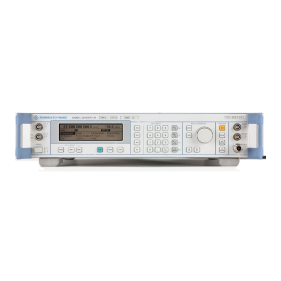
Page 32: Explanation Of Front And Rear Panel
Front Panel R&S SMR Explanation of Front and Rear Panel Elements of the Front Panel EXT 1 PULSE EXT 2 EXT1 Input external modulation signal alternatively for AM, FM, ASK and FSK. EXT2 Input external modulation signal alternatively for AM and FM. PULSE Input for triggering the pulse generator or for direct control of the pulse modulation. - Page 33 R&S SMR Front Panel DATA INPUT Numeric input field Numeric values, decimal point and minus sign can be entered by means of the digital keys. 0...9 Enters the digit. Enters the decimal point Enters the minus sign. Deletes the last input (digit, sign or decimal point) - key [BACKSPACE] Unit keys with enter function The unit keys terminate the input of values and specify the...
-
Page 34: Front Panel
Front Panel R&S SMR MENU/VARIATION Menu keys The menu keys access the menus and settings within the menus. SELECT Acknowledges the choice marked by the menu cursor. BACK Returns the menu cursor to the next higher menu level. Moves the digit cursor to the left by one position in the marked value indication. - Page 35 R&S SMR Front Panel FUNCTION HELP* Indicates context-sensitive auxiliary text. STATUS* Indicates the instrument status. ON/OFF Switches on/off the modulation selected in Utilities - ModKey. ON/OFF Switches on/off the RF signal. Cf. Chapter 4, Sections "The Help System", "Status", and Chapter 3, Section "Use of [MOD ON/OFF] and [RF ON/OFF] keys".
- Page 36 Front Panel R&S SMR QUICK SELECT The menu-quick-selection keys permit fast access to two menus selected. ASSIGN Stores the current menu as menu1 when the MENU1 key is pressed afterwards or as menu2 when the MENU2 key is pressed afterwards. MENU1 Activates menu1 stored.
-
Page 37: Elements Of The Rear Panel
R&S SMR Rear Panel Elements of the Rear Panel Output of the internal 10-MHz-reference signal with reference internal. Input for external reference frequency 10 MHz with reference external. LF Output LF signal of the internal LF-generator.LF Output LF signal of the internal LF-generator. Cf. -
Page 38: Rear Panel
Rear Panel R&S SMR RS-232 RS-232-C interface used for software update and remote control. The pin assignment corresponds to the pin assign- ment of a PC. Cf. Chapter 5, Section "Interface RS-232-C". IEEE 488 SCPI IEC 625 IEC-bus (IEEE 488) IEEE 488 Interface for Remote Control Cf. - Page 39 R&S SMR Rear Panel SYNC SYNC Output SYNC signal for pulse modulation. Cf. Chapter 4, Sections "Pulse Modulation" and "PULSE/VIDEO Output". X AXIS V / GHz TRIG / STOP X-AXIS Output voltage ramp 0 to 10 V in the sweep operating mode.
-
Page 41: Short Tutorial
R&S SMR Sample Setting for First Users Short Tutorial The present chapter contains a short tutorial with sample settings allowing the users to operate immediately the instrument. Sample Setting for First Users Setting frequency and level of the RF output signal First frequency and level of the RF output signal are set via keys [FREQ] and [LEVEL] in the DATA INPUT field: - frequency... - Page 42 Sample Setting for First Users R&S SMR AM modulation of the output signal The output signal is to be amplitude-modulated next. - AM modulation depth 30 % - AM signal 1-kHz sine Operating steps Explanations MENU / VARIATION MENU / VARIATION Select menu Modulation using rotary knob.
- Page 43 R&S SMR Sample Setting for First Users Operating steps Explanations MENU / VARIATION MENU / VARIATION Select LF generator as modulation source using rotary knob. The selection mark marks LFGen. LFGen SELECT Press [SELECT] key or rotary knob. The cursor is set back to AM Source. Press [BACK] key.
- Page 44 Sample Setting for First Users R&S SMR Setting the step width Subsequently to the above setting, 4.2 GHz as new RF frequency and 12 kHz as the step width for the RF frequency variation are set in the following. Operating steps Explanations Reset the menu cursor to the main BACK...
- Page 45 R&S SMR Sample Setting for First Users Operating steps Explanations MENU / VARIATION MENU / VARIATION Select parameter Knob Step using rotary knob. Press [SELECT] key or rotary knob. Knob Step SELECT A pop-up menu displays the available settings. MENU / VARIATION Select User (user-defined step width) using rotary knob.
-
Page 47: Manual Operation
R&S SMR Design of the Display Manual Operation This chapter shows the design of the display and describes the manual control of the microwave signal generator, for example calling up of menus, selection and editing of parameters, use of the list editor and the SAVE/RECALL function. -
Page 48: Basic Operating Steps
Basic Operating Steps R&S SMR Basic Operating Steps To operate the instrument, menus are called in the display. All setting possibilities and the current setting status are evident from the menus. All settings can be made by accessing the menus. RF frequency and RF level can also be set without menu operation using keys [FREQ] and [LEVEL]. -
Page 49: Selection And Change Of Parameters
R&S SMR Basic Operating Steps Selection and Change of Parameters Select parameter � Set the menu cursor to the name of the parameter desired using the rotary knob, e.g. to AM Depth in the AM menu, cf. Fig. 3-2. Change setting �... -
Page 50: Quick Selection Of Menu (Quick Select)
Basic Operating Steps R&S SMR 1-out-of-n selection � Select parameter. � Press [SELECT] key or rotary knob. A pop-up menu displays a selection of settings. � Set the menu cursor to the position desired within the 1-out-of-n selection using the rotary knob or cursor keys [ ] [ ]. �... -
Page 51: Use Of [Freq] And [Level] Keys
R&S SMR Basic Operating Steps Use of [FREQ] and [LEVEL] Keys RF frequency and RF level can be set without menu operation as well using direct keys [FREQ] and [LEVEL]. [FREQ] / [LEVEL] keys � Press [FREQ] or [LEVEL] key. The frequency or the level indication in the header field of the display is marked. -
Page 52: Correction Of Input
Basic Operating Steps R&S SMR Correction of Input Digits can be corrected by one of the following keys before the input is confirmed by the [Enter] key: The backspace key deletes the value entered digit by digit. When the last Key [-/ �] digit is deleted, the previous value is displayed. -
Page 53: List Editor
R&S SMR List Editor List Editor The SMR offers the facility of generating lists for automatic sequences (list mode, memory sequence) or for user-defined level correction (Ucor). The lists consist of elements (pairs of values) which are defined by an index and at least one parameter per index. Each list is assigned a separate name and selected by means of this name. - Page 54 List Editor R&S SMR Auto Normal setting. The mechanically switched attenuator switches in Attenuator Mode steps of 10 dB at fixed points. IEC/IEEE bus command :OUTP:AMOD AUTO Fixed Level settings are made without switching the attenuator (see section "Non-Interrupting Level Setting"). IEC/IEEE bus command :OUTP:AMOD FIX Atten Fixed Range...
-
Page 55: Select List
R&S SMR List Editor Select List � Mark the desired list using the rotary knob (see Fig. 3-4). � Press the [SELECT] key or the rotary knob. The selected list is included in the instrument setup. The selection window is closed. The selected list is displayed under Select List. -
Page 56: Edit List
List Editor R&S SMR Edit List When Edit List is selected, a pop-up menu with the editing functions opens. Insert editing function (see Fig. 3-6) The Insert function inserts a desired number of elements with constant or linearly increasing/decreasing values ahead of the element with the indicated start index. All elements already existing from the start index are shifted so that they come at the end of the range of elements to be inserted. - Page 57 R&S SMR List Editor Selection: Insert Fig. 3-6 Edit function Insert Insert At Input of start index. Number of elements to be inserted. Range Start Frequency Input of start value for the frequency. Increment Frequency Input of increment between two successive frequency values. If 0 is entered as an increment, identical values will be inserted.
- Page 58 List Editor R&S SMR Fill editing function (see Fig. 3-7) The Fill function overwrites a parameter with constant or linearly increasing/decreasing values within a defined range. If the [BACK] key is pressed, the editing window will be exited without any change being made.
- Page 59 R&S SMR List Editor Edit/View editing function (see Fig. 3-8) The Edit/View function allows viewing of a complete list or editing individual values of a list. If the cursor is on a value in the left column of the list, the Edit/View mode can be exited by pressing the [BACK] key.
- Page 60 List Editor R&S SMR Delete editing function (see Fig. 3-9) The Delete function deletes the elements of the indicated range. After a delete no gap is left in the list but the remaining elements move up. If the indicated range extends beyond the end of the list, the elements until the end of the list are deleted.
-
Page 61: Save/Recall - Storing/Calling Of Instrument Settings
R&S SMR SAVE/RECALL – Storing/Calling of Instrument Settings SAVE/RECALL – Storing/Calling of Instrument Settings 50 complete instrument settings can be stored in memory locations 1 to 50. Operating Steps Explanations DATA INPUT Store current instrument setting in memory location 12. SAVE dB(m) ENTER... -
Page 62: Menu Summary
Menu Summary R&S SMR Menu Summary Frequency Level Level Ucor Modulation (Option SMR-B5) (Option SMR-B5) Pulse Digital Mod (Option SMR-B5) (Option SMR-B5) (Option SMR-B5) LF Output (Option SMR-B14) Pulse Output Sweep Freq Level LFGen (Option SMR-B5) List Display GPIB Utilities System RS232 Ref Osc... -
Page 63: Index
R&S SMR Index 4 Index This chapter contains the index for the present operating manual. REF................1.9 RF ................1.11 TRIG/STOP ..............1.11 Attenuator ................3.8 Insert AUX interface..............1.9 List entry ..............3.10 Instrument settings call................3.15 store................3.15 Call Interface instrument settings ............. - Page 64 Index R&S SMR Memory Rear panel................1.9 locations ..............3.15 Recall Memory CMOS-RAM............1.3 instrument settings............3.15 Menu access ................3.2 input/output ..............1.9 call ................3.4 RF input................1.11 fields ................3.1 Rotary knob ............1.6, 3.2, 3.3 Modulation - AM ............3.2 RS-232-C interface............
- Page 65 For your User Documentation CD-ROM...
Need help?
Do you have a question about the SMR20 and is the answer not in the manual?
Questions and answers