Table of Contents
Advertisement
Quick Links
Advertisement
Table of Contents

Related Manuals for SunTech ST210


Summary of Contents for SunTech ST210
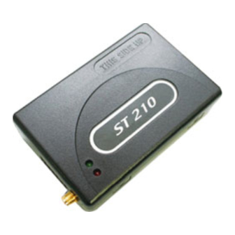
- Page 1 ST210 User Guide Suntech International Ltd.
-
Page 2: Table Of Contents
Table of Contents 1. Introduction ............................1 2. Parameter Setting via SMS........................1 For reporting GPS position, the device should be set with adjustable parameters before installation.............................. 1 When SMS for setting is sent, the device replies response to predefined server though GPRS and sets corresponding parameters. -
Page 3: Introduction
10-09-02 1.15 ST210 1. Introduction This document describes Configuration, Parameter Setting and Installation Procedure of ST210 (including back- up battery). 2. Parameter Setting via SMS For reporting GPS position, the device should be set with adjustable parameters before installation. When SMS for setting is sent, the device replies response to predefined server though GPRS and sets corresponding parameters. -
Page 4: Report Parameter Setting
Doc. Type Author Page User Guide JH KIM 2/11 Model Rev. Date 10-09-02 1.15 ST210 2.2 Report Parameter Setting Field Definitions Unit Remark “SA200RPT” Command type DEV_ID 6 char. Device ID “02” Protocol Version String Interval for sending status report in parking mode... -
Page 5: Deactivate Output1
Doc. Type Author Page User Guide JH KIM 3/11 Model Rev. Date 10-09-02 1.15 ST210 2.4 Deactivate Output1 Field Definitions Unit Remark CMD_ID “Disable1” Disable Output1 <example> [command] SA200CMD;850000;02;Disable1 [response] SA200CMD;Res;850000;010;Disable1 <notes> ** Output1 line goes to inactive status. 2.5 Activate Output2... -
Page 6: Installation
Doc. Type Author Page User Guide JH KIM 4/11 Model Rev. Date 10-09-02 1.15 ST210 3. Installation 3.1 Bottom case. 3.2 Remove battery cover. 3.3 Insert SIM card. -
Page 7: Install Back-Up Battery
Doc. Type Author Page User Guide JH KIM 5/11 Model Rev. Date 10-09-02 1.15 ST210 3.4 Install back-up battery. -
Page 8: Lock Battery Cover
Remember that if once these wires are allocated for one feature, they cannot be used for other application. If you don’t want to use Ignition and other events, you can supply power using cigar power cable. Connect 10pin to ST210 and opposite side to cigar socket in vehicle. -
Page 9: Connect Gps Antenna
Model Rev. Date 10-09-02 1.15 ST210 In this case, you have to set IGNITION in Service Parameter to ‘0’. Refer to OperationDescription document for more detailed information about parameters. 3.7 Connect GPS antenna. ST210E needs to connect GPS antenna. 3.8 Check GPS/GPRS operation with LEDs. -
Page 10: Trouble Shooting (Led Indicator)
Page User Guide JH KIM 8/11 Model Rev. Date 10-09-02 1.15 ST210 4. Trouble Shooting (LED Indicator) 4.1 Red LED: Indicates GPRS status. GPRS Blink Count Remarks Normal Server Com. Error <Possible Cause> 1. Server or network parameter is wrong. -
Page 11: Green Led: Indicates Gps Status
User Guide JH KIM 9/11 Model Rev. Date 10-09-02 1.15 ST210 4.2 Green LED: Indicates GPS status. Blink Count Remarks Normal No Fix <Possible Cause> 1. If power on, GPS chipset is trying to find position during some minutes. 2. GPS antenna lays on weak or no GPS signal position 3.
Need help?
Do you have a question about the ST210 and is the answer not in the manual?
Questions and answers