Advertisement
1. Scope:
Initial steps to quickly connect the ST4340LC to a PC, configure Network Parameter settings using SyncTrak and
assemble for use. For detailed specifications and programming information please see the links below or
contact Suntech Support at
2. Related Suntech Documentation:
a.
Suntech ST4340LC Documentation
b.
ST4000 Series SIM Card Information
c.
ST4000 Series-LED Activity and Diagnostic Guide
d.
SyncTrak User Manual
3. Required Resources:
a.
HW: Suntech ST4340LC, 6 assembly screws, USB to Micro-USB cable
b.
HW:
12v DC power supply
c.
HW: SIM card: Activated, Access Point Name (APN) for carrier/network
d.
HW: PH#1 or PH#2 Screwdriver (Torque Driver recommended)
e.
HW: PC Computer: Windows 10 recommended
f. SW: Suntech MediaTek (MTK) USB drivers: v1.1032.3 or newer, available
g.
SW: Suntech SyncTrak: v5.0.6.5 or newer,
4. Connect the ST4340LC to a PC
a. Remove the ST4340LC lid to access the SIM card holder, Micro-USB and backup battery connectors, see
Figure 2.
ST4340LC Quick Start Guide
Connect, Configure and Assemble
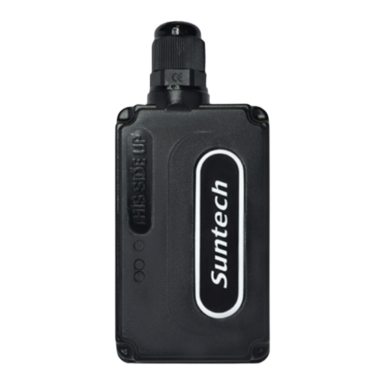
Figure 1: ST4340LC
support@suntechus.com.
available
at
support@suntechus.com
at
support@suntechus.com
SU-P-015-RevA, 1/5/2021
Page 1 of 7
Advertisement
Table of Contents

Subscribe to Our Youtube Channel
Summary of Contents for SunTech ST4340LC
- Page 1 Figure 1: ST4340LC 1. Scope: Initial steps to quickly connect the ST4340LC to a PC, configure Network Parameter settings using SyncTrak and assemble for use. For detailed specifications and programming information please see the links below or contact Suntech Support at support@suntechus.com.
- Page 2 SIM card and a false “No Sim” reading from the device, see Figure 4. Figure 3: Install SIM card Figure 4: Ensure the SIM card holder lid is locked in place b. Insert the Micro-USB cable into the ST4340LC and connect to a PC, see Figure 5. Page 2 of 7...
- Page 3 Figure 5: Inserting the Micro-USB cable connector a. Connect the ST4340LC to 12v DC power. Black wire (-), red wire (+). The device’s red and blue LEDs will begin to blink on the backside of the ST4340LC indicating the device is powered up, see Figure 6. If the ST4340LC has a 2-Pin Molex connector attached confirm mating connector’s (+) and (-) orientation...
- Page 4 “MTK USB Debug Port (COMyy)” and “MTK USB Modem Port (COMzz)”. SyncTrak will use the MTK USB Modem Port to communicate with the ST4340LC, circled in green in Figure Note: Your PC may assign a different COM port value.
- Page 5 Parameters may prevent the device from connecting and is not indicative of a failed device. To fully configure the device please see the links at the beginning of this document or contact Suntech Support at support@suntechus.com. a. Navigate to the Network Parameters tab, refer to Figure 12 below as needed.
- Page 6 If no User ID, Password or PIN is required: select None in Authentication(1000). ii. Contact Suntech Support if you require the use of the User ID, Password and PIN fields. e. Server IP(1005): Enter Server IP address (or URL).
- Page 7 Disconnect the Micro-USB cable from the ST4340LC. Next, connect the ST4340LC’s back up battery, see Figure 13. Note the Red wire on the connector should be towards the cable connected end of the device. Tuck the extra length of wire into the device to prevent pinching during assembly.


Need help?
Do you have a question about the ST4340LC and is the answer not in the manual?
Questions and answers