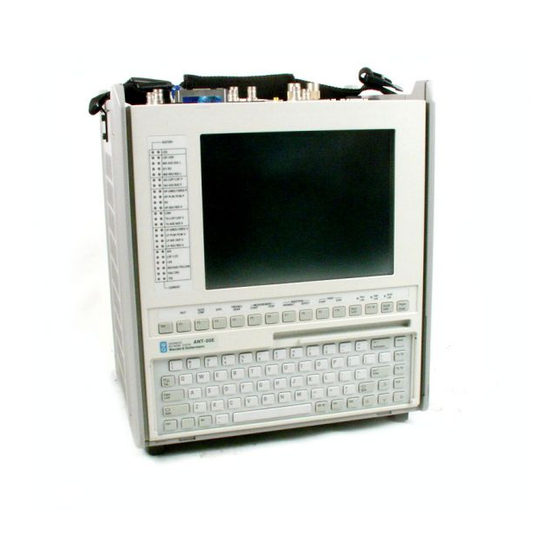
Wavetek ANT-20 Operating Manual
Advanced network tester
Hide thumbs
Also See for ANT-20:
- Operating manual (126 pages) ,
- Operating manual (4 pages) ,
- Operating manual (86 pages)
Table of Contents
Advertisement
Quick Links
Download this manual
See also:
Operating Manual
Advertisement
Table of Contents

Related Manuals for Wavetek ANT-20

Summary of Contents for Wavetek ANT-20
- Page 1 ANT-20, ANT-20E Advanced Network Tester for BN 3035/90.70 and BN 3035/90.80 ATM Mappings BN 3035/90.71 to 90.77 Software Version 7.20 Operating Manual...
- Page 2 Please direct all enq uiri es to your local W avetek Wand el Golter mann sales co mpany. The addresse s are given at the end of t his ha ndb ook. Copyrig hts This produc t or parts of it are based upon Recom mendat ions and/or Standards o f the Stand ardization Sector o f th e Inte rnational Teleco mmunication Un ion - ITU-T and/or o f the...
-
Page 3: Table Of Contents
ANT-20/ANT-20E ATM Mappings Contents Specifications STM-1 C4, ATM in 155.52 Mbit/s mapping ....S-1 STS-3c, ATM in 155.52 Mbit/s mapping ..... . S-2 STS-1, ATM in 51.840 Mbit/s mapping . - Page 4 ATM Mappings ANT-20/ANT-20E DS1, ATM in 1.544 Mbit/s mapping ......S-14 Alarm generation (defects) ......S-14 Error insertion (anomalies) .
-
Page 5: Specifications
ANT-20/ANT-20E ATM Mappings Specifications STM-1 C4, ATM in 155.52 Mbit/s mapping This mapping structure is included in the following instrument versions and options: • ATM Module, BN 3035/90.70 • Broadband Analyzer/Generator, BN 3035/90.80 Fig. S-1 150 Mbit/s in STM-1/STS-3c ATM cell stream mapping structure For the following topics please refer to the specifications of the “STM-1 Mappings”... -
Page 6: Sts-3C, Atm In 155.52 Mbit/S Mapping
ATM Mappings ANT-20/ANT-20E STS-3c, ATM in 155.52 Mbit/s mapping This mapping structure is included in the following instrument versions and options: • ATM Module, BN 3035/90.70 • Broadband Analyzer/Generator, BN 3035/90.80 For the following topics please refer to the specifications of the “STS-1 Mapping” file (section “STS-3c Mapping”:... -
Page 7: Sts-1, Atm In 51.840 Mbit/S Mapping
ANT-20/ANT-20E ATM Mappings STS-1, ATM in 51.840 Mbit/s mapping Option 3035/90.71 • Includes the ATM mapping for STS-1 in accordance with ITU-T G.707 and ANSI Draft T1.105.02-199X. 87 octets 9 rows STS-1 POH fixed stuffing ATM cell 53 octets Fig. S-2 ATM mapping for STS-1 (51.840 Mbit/s) -
Page 8: E4, Atm In 139.264 Mbit/S Mapping
ATM Mappings ANT-20/ANT-20E E4, ATM in 139.264 Mbit/s mapping Option 3035/90.72 • Frames to G.832. • ATM mapping to G.804. Overhead Overhead byte Option 3035/90.72 FA1(hex) “F6” FA2 (hex) “28” EM (hex) Inserted via parity formation TR (ASCII) “WG E4-TRACE”... -
Page 9: Error Insertion (Anomalies)
ANT-20/ANT-20E ATM Mappings Error insertion (anomalies) Trigger modes ........... Single or Rate... - Page 10 ATM Mappings ANT-20/ANT-20E E3, ATM in 34.368 Mbit/s mapping Option 3035/90.74 • Frames to G.832. • ATM mapping to G.804 Overhead Overhead byte Option 3035/90.74 FA1(hex) “F6” FA2 (hex) “28” EM (hex) Inserted via parity formation TR (ASCII) “WG E3-TRACE MA (hex) “10”...
-
Page 11: Error Insertion (Anomalies
ANT-20/ANT-20E ATM Mappings Error insertion (anomalies) Trigger modes ........... Single or Rate... -
Page 12: E1, Atm In 2.048 Mbit/S Mapping
ATM Mappings ANT-20/ANT-20E E1, ATM in 2.048 Mbit/s mapping Option 3035/90.75 • ATM mapping according to ITU-T G.804. TS16: signalling 256 bits/125 µs Header Header Header Header Mapping section for ATM cells: 30 octets (TS1 to TS15 and TS17 to TS31) -
Page 13: Ds3, Atm In 44.736 Mbit/S Mapping (Plcp, Hec Based)
ANT-20/ANT-20E ATM Mappings DS3, ATM in 44.736 Mbit/s mapping (PLCP, HEC based) Option 3035/90.73 PLCP-based Mapping The ATM cells are firs mapped into PLCP frames (Physical Layer Convergence Protocol) as per G.804. The PLCP frame slips bit-synchronously (Nibble-aligned floating-4 bit) into DS3 C Parity frames as per G.804 (G.704). -
Page 14: Alarm Generation (Defects)
ATM Mappings ANT-20/ANT-20E 7.1.2 Alarm generation (defects) The following alarm types (defects) can be generated: Defect Sensor function test Sensor thresholds on/off M in N AIS_DS3 IDLE_DS3 LOF_DS3 YELLOW_DS3 (RDI) PLCP_LOF M = 1 to N-1; N = 1 to 8000... - Page 15 ANT-20/ANT-20E ATM Mappings 7.1.4 Error measurement (anomalies) The following error types can be displayed and evaluated in addition to the error types provided by the Mainframe. Anomaly FE_DS3, MFE_DS3 FAS/CRC P_DS3, CP_DS3 FEBE_DS3 PLCP_FAS FAS/CRC PLCP_B1 B1/B2 PLCP_REI (FEBE) Table S-13 LED display of possible anomalies 7.1.5...
-
Page 16: Hec-Based Mapping
ATM Mappings ANT-20/ANT-20E HEC-based Mapping The G.704 multiframe is used for HEC-based mapping of ATM cells into 44.736 Mbit/s as per G.804. 7.2.1 Alarm generation (defects) Defect Sensor function test on/off AIS_DS3 IDLE_DS3 LOF_DS3 YELLOW_DS3 (RDI) Table S-15 Alarm generation (defects): Available alarm types 7.2.2... - Page 17 ANT-20/ANT-20E ATM Mappings 7.2.4 Alarm detection (defects) Defect LOF_DS3, OOF_DS3 LOF/LCD YELLOW_DS3 IDLE_DS3 Table S-18 Alarm detection (defects): LED display of possible defects Specifications S-13...
- Page 18 ATM Mappings ANT-20/ANT-20E DS1, ATM in 1.544 Mbit/s mapping Option 3035/90.76 Alarm generation (defects) Defect Sensor function test on/off AIS_DS1 LOF_DS1 YELLOW_DS1 Table S-19 Alarm generation (defects): Available defects Error insertion (anomalies) Trigger types ............Single error...
-
Page 19: Alarm Detection (Defects
ANT-20/ANT-20E ATM Mappings Alarm detection (defects) The following alarms can be displayed and evaluated in addition to the defects provided by the Mainframe. Defect AIS_DS1 LOF_DS1, OOF_DS1 LOF/LCD YELLOW_DS1 Table S-22 Alarm detection (defects): LED display of available defects Specifications... -
Page 20: Stm-1 C3, Atm In 155.52 Mbit/S Mapping
ATM Mappings ANT-20/ANT-20E STM-1 C3, ATM in 155.52 Mbit/s mapping Option 3035/90.77 Fig. S-4 Mapping structure AU-4: ATM “→” C-3 “→” AU-4“→” STM-1 Fig. S-5 Mapping structure AU-3: ATM “→” C-3 “→” AU-3“→” STM-1 For the following topics please refer to the specifications of the “STM-1Mapping” file: •... -
Page 21: Sts-1 Spe, Atm In 44.736 Mbit/S Mapping
ANT-20/ANT-20E ATM Mappings 10 STS-1 SPE, ATM in 44.736 Mbit/s mapping see Sec. 3, Page S-3 and Sec. 7, Page S-9 11 VC3, ATM in 44.736 Mbit/s mapping see Sec. 7, Page S-9 and Sec. 9, Page S-16 Specifications S-17... - Page 22 ATM Mappings ANT-20/ANT-20E Notes: S-18 Specifications...
Need help?
Do you have a question about the ANT-20 and is the answer not in the manual?
Questions and answers