Table of Contents
Advertisement
Quick Links
Advertisement
Table of Contents

Related Manuals for AeroWorks Katana S


Summary of Contents for AeroWorks Katana S
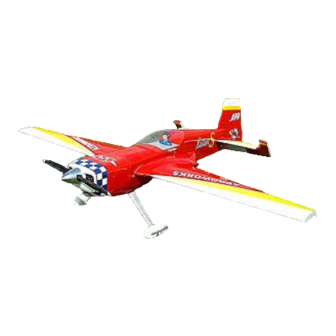
- Page 1 29% KATANA ARF ASSEMBLY MANUAL...
- Page 2 It is important to notify Aeroworks of any damage or problems with the model immediately. If you wish to return this aircraft for any reason a 15% restock fee will be charged to the customer. In addition the customer is responsible for all return shipping cost and all prior-shipping costs will not be refunded.
-
Page 3: Equipment Requirements
EQUIPMENT REQUIREMENTS AILERONS: (2) Servo’s: 70 Ounce minimum, two per wing. You may select to use only one servo per wing panel. If you do, you will need to place it in the servo slot toward the root end of the wing and you must use a 130-ounce minimum servo. -
Page 4: Fuselage Assembly
Recommended throw is 35 degrees minimum up and down. We also recommend using Ultracote to seal all control surfaces. (Stronger after market CA hinges available through Aeroworks.) 2) Locate servo location on bottom side of wings and remove covering. Attach servo extension leads to your servo. - Page 5 4) When setting up the servo linkage, we recommend using 4-40 rod with a silver solder clevis. It is very important to have all control linkages 90 degrees to the control surface and servo arm. If more throw is required then the silver solder clevis will allow, we recommend using a Dubro swivel ball link at the servo arm for more movement.
-
Page 6: Stab And Elevator Assembly
STAB AND ELEVATOR ASSEMBLY 1) Locate the pre cut hinge slots in the stab and elevator. The model comes with CA style hinges pre installed, but not glued into the control surfaces. If you wish to use the CA hinges we recommend adding hinges to each surface and use thin CA when gluing in hinges. - Page 7 3) Locate hardwood blocks pre installed in the elevators. Drill and tap block for control horn locations for a 8/32 bolt. Install the control horns so your linkage will be 90 degrees to the servo arm. We recommend using the Nelson control horn assembly #RCL70. DO NOT counter sink bolt head. Use flush mount bolt 4) When setting up the servo linkage we recommend using 4-40 rod with a silver solder clevis.
- Page 8 ENGINE BOX ASSEMBLY 1) Cut 1/8” ply engine box sides to correct length to accommodate your engine size (Be sure to cut from front of engine box sides) An easy way to determine the correct length of box sides is to slide the cowl just past Former F1 approximately 1/8”.
-
Page 9: Landing Gear
FIN AND RUDDER ASSEMBLY 1) Locate the hardwood block pre installed in the rudder for the control horn. Drill and tap for 8-32 all thread. Install all thread into rudder and secure with flat washer and nut on each side. You should have approximately 1”... -
Page 10: Tail Wheel
TAIL WHEEL 1) Locate tail wheel steering hard point towards bottom of rudder. Drill a hole big enough for 4-40 rod to slide through. 2) Slide rod through rudder center rod and epoxy in place. Attach strip aileron horns to ends of rods. Make sure rod sticks out 1”... -
Page 11: Canister Muffler Installation
Measure Engine thrust line 1 1/4” down from top of Offset center box sides of engine 3/8” to compensate Firewall for right thrust Centerline 1) Fit cowl to fuse cutting out where needed to accommodate engine. Remember to fit cowl over fuse 1/8”. - Page 12 Note: If you are not going to install canister mufflers, do not cut the covering from the bottom of the airplane. You must still attach bottom hatch cover with 4 4-40 bolts and blind nuts, but you do not need to do anything else.
-
Page 13: Center Of Gravity
INSTALLING WHEEL PANTS 1) Make a notch in the wheel pant and lite-ply mounting plate with a Dremel drum sander. Make the notch deep enough to let the wheel pant slide over the axle to the desired height. 2) Align the wheel pant to the gear and with 1/8” drill bit, drill two equally spaced holes through gear and wheel pant. - Page 14 C.G. 4 1/4” back form leading edge of wing tip FLYING We believe the Katana will be one of the finest flying airplanes you will ever fly. The Katana has no bad habits and very slow speed stall characteristics. Inverted flight is nearly hands off and knife-edge flight takes little or no mixing to remain straight and true. Remember the Katana is a large aircraft and picks up speed quickly when coming out of split S type maneuvers or when needing straight downward.
- Page 15 Secure battery with Always hooks and rubber protect wires bands Optional rudder servo location if you wish to use a pull-pull system. Typical radio and tank installation Shown with a DA 50 mounted and stock stand-offs Strip aileron horn Attaching spring for tail Tail wheel installation if Elevator servo installation wheel if using a pull-pull...
- Page 16 Available From Aeroworks ACCESSORIES FOR YOUR 29% KATANA AEROWORKS REALISTIC PILOTS AVAIALBLE Available in: Red, Yellow, Blue or Black Shirt color in Head Set version. DASH PANELS AVAILABLE WING BAGS AVAILABLE STAB BAGS AVAILABLE WING BAG STAB BAG HARDWARE PACKAGE AVAILABLE...
- Page 17 29% Katana HARDWARE PACKAGE PACKING LIST FUSELAGE 4/40 x ½ SOCKET HEAD CAP DU571 COWL MOUNT #4 FLAT WASHER DU 323 COWL MOUNT 4/40 BLIND NUTS DU 135 COWL MOUNT 10/32 X ¾ SOCKET HEAD CAP DU 580 LANDING GEAR 10/32 BLIND NUTS DU 584 LANDING GEAR...