Table of Contents
Advertisement
Advertisement
Table of Contents

Related Manuals for Bosch PLENA PLN-6AIO240


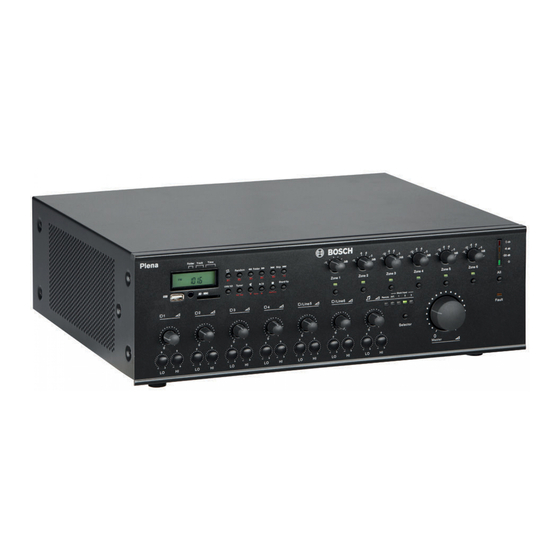
Summary of Contents for Bosch PLENA PLN-6AIO240
- Page 1 Plena All-in-One System PLN-6AIO240 Installation and Operating Manual...
-
Page 3: Table Of Contents
Internal music unit 8.2.1 USB/SD/TUNER display 8.2.2 USB connector 8.2.3 IR remote control sensor 8.2.4 SD card slot 8.2.5 Music player 8.2.6 Remote control button functions Call Station operation Bosch Security Systems B.V. Installation and Operating Manual 2014.09 | V1.2 |... -
Page 4: En | Table Of Contents
| Table of Contents Plena All-in-One System Wall Panel operation Troubleshooting Customer service Maintenance Technical Data 11.1 All-in-One unit 11.2 Call Station 11.3 Wall Panel 11.4 Safety compliance 2014.09 | V1.2 | Installation and Operating Manual Bosch Security Systems B.V. -
Page 5: Safety
Electrical and Electronic Equipment Directive). To dispose of old electrical or electronic devices, you should use the return and collection systems put in place in the country concerned. Bosch Security Systems B.V. Installation and Operating Manual 2014.09 | V1.2 |... -
Page 6: About This Manual
The equipment or the property can be seriously damaged, or persons can be severely injured if the alert is not observed. Danger! Not observing the alert can lead to severe injuries or death. 2014.09 | V1.2 | Installation and Operating Manual Bosch Security Systems B.V. -
Page 7: Conversion Tables
For information on getting permission for reprints and excerpts, contact Bosch Security Systems B.V.. The content and illustrations are subject to change without prior notice. -
Page 8: System Overview
"All-In-One" system – Voice Alarm System – Timer – Charger – Loop amplifier The various elements are designed to complement each other using matched acoustical, electrical and mechanical specifications. 2014.09 | V1.2 | Installation and Operating Manual Bosch Security Systems B.V. -
Page 9: Plena All-In-One System
The Plena All‑in‑One System is an all‑in‑one solution for making announcements, paging people and playing background music (BGM). The system consists of the following products, which can be ordered separately: – PLN‑6AIO240 All‑in‑One Unit Figure 3.1: All‑in‑One Unit block diagram Bosch Security Systems B.V. Installation and Operating Manual 2014.09 | V1.2 |... - Page 10 The PLE‑1CS or PLE‑1SCS Call Station is an all‑call call station that can be used with the All‑in‑One Unit for making announcements without zone selection. It is connected to the All‑in‑One Unit using a shielded Cat‑5 cable terminated with RJ45 connectors. 2014.09 | V1.2 | Installation and Operating Manual Bosch Security Systems B.V.
-
Page 11: Packaging And Transportation
Caution! Do not use sharp or pointed objects. – If any items are missing, notify your Bosch representative. – The original packaging is the safest container in which to transport products and can be used to return products for service if necessary. -
Page 12: Installation
A maximum of six call stations can be configured for each All-in-One Unit. The maximum cable distance from the All-in-One Unit to the last Call Station is 600 m. 2014.09 | V1.2 | Installation and Operating Manual Bosch Security Systems B.V. -
Page 13: Install Wall Panel
Gently position the control panel in the mounting bracket, taking care not to damage the printed circuit board or the RJ45 cable. Secure the control panel with the four attachment screws. Do not over-tighten. Bosch Security Systems B.V. Installation and Operating Manual 2014.09 | V1.2 |... -
Page 14: Connection
Music input 3 sensitivity: 300 mV, 10 kohm unbalanced. Music input 1 TRS-jack/XLR connector to connect an external mono music source. – Input 1 sensitivity: 500 mV, 10 kohm unbalanced. 2014.09 | V1.2 | Installation and Operating Manual Bosch Security Systems B.V. - Page 15 A balanced 100 V input, compatible with loudspeaker line signals. This input input has a gate function (VOX); when the signal level exceeds a -10 dB level, it gets the highest priority and overrides all other inputs. Bosch Security Systems B.V. Installation and Operating Manual 2014.09 | V1.2 |...
- Page 16 The external amplifier can be used as spare amplifier or as a second amplifier in dual‑channel mode. – Current rating maximum 7 A (50 Hz to 20 kHz). 2014.09 | V1.2 | Installation and Operating Manual Bosch Security Systems B.V.
-
Page 17: Microphone Adaptor Connections
PLE-1SCS Call Station to Input 1 RJ45 connector (42). An unshielded Cat-5 cable may pick up hum and is not recommended. Figure 6.2: Microphone Adaptor Figure 6.3: Microphone Adaptor connector layout Bosch Security Systems B.V. Installation and Operating Manual 2014.09 | V1.2 |... -
Page 18: Call Station Connections
RJ45 connector is delivered with each Call Station. See Delivered with products, page 11. When Call Stations are cascaded some terminators are left unused, as only the last Call Station is terminated. 2014.09 | V1.2 | Installation and Operating Manual Bosch Security Systems B.V. - Page 19 A maximum of six Call Stations can be connected in cascade. The maximum cable length to the last Call Station is 600 m and the last Call Station must have a terminator plug inserted in the loop through connector. Bosch Security Systems B.V. Installation and Operating Manual 2014.09 | V1.2 |...
-
Page 20: Wall Panel Connections
Note: Do NOT use a RJ45 cable boot or sleeve to terminate this cable. This may result in the cable not fitting into the device or its bend radius being exceeded. 2014.09 | V1.2 | Installation and Operating Manual Bosch Security Systems B.V. -
Page 21: Configuration
(25), the internal power amplifier will also serve as a spare amplifier for the call channel. In dual channel mode, zones with music will not be interrupted by calls to another zone. Bosch Security Systems B.V. Installation and Operating Manual 2014.09 | V1.2 |... - Page 22 PLE-1CS or PLE-1SCS is not disabled but just mixed with Microphone input 1, without a chime signal. MOH level adjustment Adjusts the output level of the “Music On Hold” signal on outputs (44) and (45). 2014.09 | V1.2 | Installation and Operating Manual Bosch Security Systems B.V.
-
Page 23: Priority Switches
Switch setting Chime Frequency No chime 1-tone chime 554 Hz 2-tone chime 554/440 Hz 4-tone chime 294/392/495/588 Hz Table 7.2: Chime switches settings Bosch Security Systems B.V. Installation and Operating Manual 2014.09 | V1.2 |... -
Page 24: Call Station Hardware Configuration
All‑in‑One Unit to make sure that each call comes through. 2014.09 | V1.2 | Installation and Operating Manual Bosch Security Systems B.V. -
Page 25: Call Station Software Configuration
Press the PTT button to store the selected ID for this call station and exit. Call station ID Zone 4 LED Zone 3 LED Zone 2 LED Zone 1 LED Table 7.3: Call station ID settings Bosch Security Systems B.V. Installation and Operating Manual 2014.09 | V1.2 |... -
Page 26: Microphone Sensitivity
This setting determines what happens when more than one Call Station is connected to the All‑in‑One Unit. For consistent behavior make sure that all connected Call Stations use the same setting. 2014.09 | V1.2 | Installation and Operating Manual Bosch Security Systems B.V. -
Page 27: Chime Selection
Press one button (from buttons Zone 1-6) to store the zone group setting. All Zone 1-6 LEDs flash again. Then select the required zones for this zone group. Press the PTT button to store the created zone groups and exit. Bosch Security Systems B.V. Installation and Operating Manual 2014.09 | V1.2 |... -
Page 28: Wall Panel Configuration
Install drawing Wall Panel, page 13. – Jumper connected: phantom power ON. – Jumper removed: phantom power OFF. 2014.09 | V1.2 | Installation and Operating Manual Bosch Security Systems B.V. -
Page 29: Operation
LO = 100 Hz ± 8 dB – HI = 10 kHz ± 8 dB Inputs 5‑6 level control A rotary control to adjust the Microphone/Line 5‑6 signal levels. Bosch Security Systems B.V. Installation and Operating Manual 2014.09 | V1.2 |... - Page 30 Indicates the output signal level. Accuracy is between +0 / -3 dB, where: – 0 dB = red – -6 dB = amber – -20 dB = amber – Power on = green 2014.09 | V1.2 | Installation and Operating Manual Bosch Security Systems B.V.
- Page 31 Risk of potential damage to unit. Before connecting power, always check the voltage selector (17) (on the rear panel of the unit) to ensure it is set to the correct country voltage. Bosch Security Systems B.V. Installation and Operating Manual 2014.09 | V1.2 |...
-
Page 32: Internal Music Unit
USB/SD/TUNER display, page 33 USB connector, page 33 IR remote control sensor, page 33 SD card slot, page 34 Music player, page 34 Each item is explained in the following sections. 2014.09 | V1.2 | Installation and Operating Manual Bosch Security Systems B.V. -
Page 33: Usb/Sd/Tuner Display
The IR sensor (3) receives an IR signal from the remote control supplied with the unit. The maximum distance in an open field is 10 m, and a direct line of sight is needed. Bosch Security Systems B.V. Installation and Operating Manual... -
Page 34: Sd Card Slot
The following table explains button functions that are used when the music player is in MP3 playback mode. For the location of each button, see item 5 in Section Internal music unit, page 2014.09 | V1.2 | Installation and Operating Manual Bosch Security Systems B.V. - Page 35 Stop music Press the Stop button to stop music playback. The LCD playback shows the total number of songs and folders. Table 8.2: MP3 Playback button functions Bosch Security Systems B.V. Installation and Operating Manual 2014.09 | V1.2 |...
- Page 36 4) Press a pre‑selection button (Mx) for more than 1 second. To recall a pre-selected radio station press +5 and then Mx for pre-selections M6-M10. Table 8.3: FM/AM Tuner button functions 2014.09 | V1.2 | Installation and Operating Manual Bosch Security Systems B.V.
-
Page 37: Remote Control Button Functions
M1-M10. Pressing any key interrupts the search process. Table 8.4: Remote control button functions Bosch Security Systems B.V. Installation and Operating Manual 2014.09 | V1.2 |... -
Page 38: Call Station Operation
To select a zone, press a zone button and the corresponding zone (1-6) LED will go on. – To deselect a zone, press the zone button again and the zone LED will go out. 2014.09 | V1.2 | Installation and Operating Manual Bosch Security Systems B.V. - Page 39 Green - call active, the user can speak. – Green flashing - call active, busy with attention chime. Power LED – Green LED on indicates power on. – Green LED off indicates power off. Bosch Security Systems B.V. Installation and Operating Manual 2014.09 | V1.2 |...
- Page 40 Press the SELECT button repeatedly to select between the internal music player of the All‑in‑One Unit (USB/SD/Tuner) and Music inputs 1-3. The corresponding LED lights up to show the selection. 2014.09 | V1.2 | Installation and Operating Manual Bosch Security Systems B.V.
-
Page 41: Installation And Operating Manual 2014.09 | V1.2
All‑in‑One Unit. This can be a signal on the Telephone/Emergency input or from a call station. The Enable LED will flash slowly (1 Hz) when it is deactivated. Bosch Security Systems B.V. Installation and Operating Manual 2014.09 | V1.2 |... -
Page 42: Troubleshooting
No sound output to the unit. Audio mixer is not working Check the music source correctly. selector and volume settings on the audio mixer. 2014.09 | V1.2 | Installation and Operating Manual Bosch Security Systems B.V. -
Page 43: Customer Service
Customer service If a fault cannot be resolved, please contact your supplier or system integrator, or go directly to your Bosch representative. Bosch Security Systems B.V. Installation and Operating Manual 2014.09 | V1.2 |... -
Page 44: Maintenance
The ground (Protective Earth) connection of the system components. Warning! Dangerous mains voltages are present inside the units. Disconnect the main power supply before doing any maintenance tasks. 2014.09 | V1.2 | Installation and Operating Manual Bosch Security Systems B.V. -
Page 45: Technical Data
>40 dB (50 Hz to 20 kHz) Headroom >25 dB Phantom power supply 18 V – No load Level detector (VOX) on Inputs 1-6 Attack time 150 ms; release time 3 s Bosch Security Systems B.V. Installation and Operating Manual 2014.09 | V1.2 |... - Page 46 Total harmonic distortion (1 kHz) < 0.8 % FM range 87.5 - 108 MHz Frequency response 60 Hz - 12 kHz Intermediate rejection ≥ 70 dB Image rejection ≥ 50 dB 2014.09 | V1.2 | Installation and Operating Manual Bosch Security Systems B.V.
- Page 47 Dimensions (H x W x D) 133 x 430 x 365 mm with feet (19" wide, 3 U high) Weight Approx. 18 kg Mounting Standalone, 19” rack Color Charcoal Bosch Security Systems B.V. Installation and Operating Manual 2014.09 | V1.2 |...
- Page 48 -40 ºC to +70 ºC (-40 ºF to +158 ºF) Relative humidity <95% (non‑condensing) Generic performance specifications Acoustic noise < 45 dB SPL, measured at 1 meter above the unit MTBF 1200000 hours at 25°C 2014.09 | V1.2 | Installation and Operating Manual Bosch Security Systems B.V.
-
Page 49: Call Station
2 x RJ45, Cat‑5, max. length 600 m Environmental Operating temperature -10ºC to +45ºC (14ºF to +113ºF) Storage temperature -40ºC to +70ºC (-40ºF to +158ºF) Relative humidity <95% (non‑condensing) Bosch Security Systems B.V. Installation and Operating Manual 2014.09 | V1.2 |... -
Page 50: Wall Panel
PLN‑6CS Call Station and PLN‑4S6Z Wall Panel. Safety IEC/EN 60065 EN 55103-1 EN 55103-2 EN 61000-3-2 EN 61000-3-3 Environment EN 50581 UL 60065 FCC Part 15B CSA C22.2.60065 AU/NZ C-Tick 2014.09 | V1.2 | Installation and Operating Manual Bosch Security Systems B.V. - Page 52 Bosch Security Systems B.V. Torenallee 49 5617 BA Eindhoven The Netherlands www.boschsecurity.com © Bosch Security Systems B.V., 2014...
Need help?
Do you have a question about the PLENA PLN-6AIO240 and is the answer not in the manual?
Questions and answers