Table of Contents
Advertisement
Quick Links
Advertisement
Table of Contents

Related Manuals for Flex innovations Ventique G2


Summary of Contents for Flex innovations Ventique G2
- Page 1 DESIGNED BY: ARF and Super PNP w w w . f l e x i n n o v a t i o n s . c o m...
- Page 2 BEFORE CONTINUING WITH THIS INSTRUCTION MANUAL OR ASSEMBLY OF YOUR VENTIQUE 60E G2 PRO, PLEASE VISIT OUR WIKI SUPPORT SITE FOR THE LATEST PRODUCT UPDATES, FEATURE CHANGES, MANUAL ADDENDUMS AND FIRMWARE CHANGES FOR BOTH YOUR VENTIQUE 60E G2 PRO AND THE AURA 8 ADVANCED FLIGHT CONTROL SYSTEM.
-
Page 3: Table Of Contents
TABLE OF CONTENTS Introduction ....................Aura 8 Servo Connections ............... Transmitter Setup ..................Recommended Equipment ............... Required to Complete ................. Receiver Installation for Aura 8 .............. Connecting Your Receiver to Aura 8 ............ Replacement Parts Listing ................. Optional Items ....................Connecting Battery/Arming ESC ............ -
Page 4: Replacement Parts Listing
REPLACEMENT PARTS LISTING OPTIONAL ITEMS FPM1900A Ventique 60E G2 PRO ARF+ Yellow FPZB42006S40 Potenza 6S 4200mAh 40C LiPo Battery FPM1900B Ventique 60E G2 PRO ARF+ Orange FPZB35006S75 Potenza 6S 3500mAh 75C LiPo Battery FPM1950A Ventique 60E G2 PRO SUPER PNP Yellow FPM337022 PREMIUM WING BAG –... -
Page 5: Before You Begin
All instructions, warranties and other collateral documents are subject to change at the This is NOT a toy! This product is sole discretion of Flex Innovations, LLC. For up-to-date product literature, please visit our not intended for use by children website at www.flexinnovations.com and click on the Ventique 60E G2 Pro and Aura 8... -
Page 6: Important Before Assembly
These batteries feature an EC5 connector, so no soldering is required for use in your Ventique 60E G2 Pro. All are available online at www.flexinnovations.com and your local Flex Innovations retailer. LOW VOLTAGE CUTOFF LiPo batteries have a nominal (rated) voltage of 3.7v per cell, and fully charged, reach 4.2v per cell. -
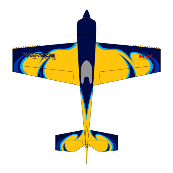
Page 7: Ventique Yellow Scheme
VENTIQUE YELLOW SCHEME -1° -1° ULTRACOAT COLORS DARK YELLOW (HAN U889) MIDNIGHT BLUE (HAN U885) SKY BLUE (HAN U875) DARK BLUE (HAN U873) -
Page 8: Ventique Orange Scheme
VENTIQUE ORANGE SCHEME -1° ° ULTRACOAT COLORS MIDNIGHT BLUE (HAN U885) ORANGE (HAN U877) WHITE (HAN U870) -
Page 9: Arf Specific Instructions
THIS SECTION CONTAINS ASSEMBLY INSTRUCTIONS FOR THE ALMOST READY TO FLY VERSION OF THE VENTIQUE 60E G2 PRO If you have the Super PNP version you can skip forward to the next section that starts on page 13. -
Page 10: Control Horn Installation
NOTICE The Flex Innovations Ventique 60E G2 Pro is designed so that you can use either a push-pull or a pull-pull rudder setup. Push-pull (servo in the tail) is the recommended setup for the Ventique and will result in the correct CG if you are using the recommended motor. The mounting location and for the pull-pull is provided on the main equipment tray and two control horns and hardware, except for the servo arm, are provided for a pull-pull installation, however, the pull-pull installation will not be covered in this manual. -
Page 11: Servo Installation
SERVO INSTALLATION Required Tools and Fasteners: (4) Servos (Potenza DS18007HV recommended) (2) 3” Aileron Servo Extensions (2) 24” Rudder Servo Extension (2) Servo Extension Safety Clips Hobby Knife with a #11 blade Mounting Hardware/tools as required by your servos 1. If you will be using the recommended push-pull rudder setup (servo in the tail), locate the opening for the for the rudder servo on the right side of the fuselage (under the elevator). - Page 12 SERVO INSTALLATION (CONTINUED) 7. Final installation of the linkages for all the control surfaces will be done when the receiver and optional Aura 8 have been installed and configured. For now we will assemble the push rods and have them ready for installation. 8.
-
Page 13: Motor And Esc Installation
MOTOR AND ESC INSTALLATION Required Tools and Fasteners: Motor (DualSky XM5050EA 515KV Recommended) ESC (Hobby Wing 100A Skywalker 100A V2 Recommended) Plywood Motor Spacer Motor hardware provided with your motor (4) M4X20 Socket Head Hex Bolts (4) M4 Washers 2.5mm Hex Driver Blue Thread Locker Cable Ties (QTY 4) -
Page 14: Arf & Super Pnp Instructions
ARF & Super PNP THIS SECTION CONTAINS ASSEMBLY INSTRUCTIONS FOR BOTH VERSIONS OF THE VENTIQUE 60E G2 PRO Note - The Flex Aura 8 is supplied with the Super PNP, however, it is optional with the ARF. The remainder of the manual assumes that you are using a Flex Aura 8 but if you are not just ignore the sections pertaining to it. -
Page 15: Horizontal Stabilizer Installation
ARF & Super PNP HORIZONTAL STABILIZER INSTALLATION Required Tools and Fasteners: 30-Minute Epoxy Isopropyl Alcohol Paper Towels 1. Remove the horizontal stabilizer filler piece from the rear of the fuselage. 2. Dry fit the horizontal stabilizer to ensure that you have a good understanding of how it will fit before you bond it in place. Ensure that it seats properly, all the way forward. -
Page 16: Rudder And Tail Wheel Installation
ARF & Super PNP RUDDER AND TAIL WHEEL INSTALLATION Required Tools and Fasteners: Rudder Hinge Piano Wire Tail Wheel Assembly (2) M2X12 Flanged Self-tapping Screws (1) M2X12 Self-tapping Screw #1 Phillips Screwdriver Thin CA adhesive (QTY 2) (QTY 1) 1. Place the rudder in position, ensure that the hinge halves line-up and that the bottom of the rudder is flush with the fuselage. Insert the rudder hinge piano wire, starting from the bottom of the fuselage, through all 4 of the rudder half hinges. -
Page 17: Main Landing Gear Installation
ARF & Super PNP MAIN LANDING GEAR INSTALLATION Required Tools and Fasteners: (4) M3X20 Socket Head Hex Bolts (4) M3 Flat Washers (6) 4mm Washers (2) M3X15 Hex Bolts 2.5mm Hex Driver 2mm Hex Driver 1.5mm Hex Driver 10mm Wrench 7mm Wrench Blue Thread Locker (QTY 4) -
Page 18: Wing Installation
ARF & Super PNP WING INSTALLATION Required Tools and Fasteners: None! 1. The Ventique 60E G2 Pro feature tool-less and screw-less field assembly. This is accomplished using the Flex Speed-lock technology. 2. Insert the tube into the fuselage and center it. 3. -
Page 19: Aura 8 Afcs
flying experience, but it never interferes with the pilot’s control. The Aura 8 AFCS comes configured with Flight Modes (dual rates, expos and gyro settings) set by the Flex Innovations team, and offers a great starting point for most pilots. -
Page 20: Transmitter Setup
ARF with Aura 8 & Super PNP TRANSMITTER SETUP If you do not plan on using an Aura 8 on your Ventique 60E G2 Pro ARF you will need to configure your transmitter and install your receiver as directed by the instructions provided with these. You can find the recommended controls throws and rates for this on page 23 of this manual. If you are using this setup you can skip this page and the next one as they pertain specifically to the Aura 8 configuration. -
Page 21: Connecting Your Receiver To Aura 8
4651T require the use of a different cable to connect to Aura. The cable is included with the receiver when it is purchased directly from Flex Innovations. You can also purchase the cable itself at flexinnovations.com (FPZA1039). Other receivers like... -
Page 22: Connecting Battery/Arming Esc
ARF & Super PNP CONNECTING BATTERY/ARMING ESC Observe the following procedures to safely power up your model after it has been bound. Ensure the propeller is removed unless this sequence is followed to power up before flight. 1. Turn on the transmitter. Lower the throttle stick AND throttle trim to their lowest settings. -
Page 23: Control Surface Linkage Installation
ARF & Super PNP CONTROL SURFACE LINKAGE INSTALLATION Required Tools and Fasteners: Elevator and Rudder Pushrod Assemblies #2 Phillips Screwdriver (8) M2x10 Phillips Head Machine Screw 1.5mm Hex Driver (12) M2 Flat Washer Needle-Nosed Pliers (or Hemostats) (8) M2 Lock Nut Blue Thread Lock (4) Servo arms and screws Super PNP NOTICE... -
Page 24: Control Surface Throws
ARF & Super PNP CONTROL SURFACE LINKAGE INSTALLATION (CONTINUED) 6. Use a 1.5mm hex driver, M2x10 machine screw, M2 washers and M2 lock nut to secure the linkage to the control horns. If you have the ARF version you will have to attach all four pushrods but if you have the Super PNP you will only have to attach the elevator and rudder pushrods as the aileron pushrods will have been installed for you at the factory. -
Page 25: Control Direction Test
ARF & Super PNP CONTROL DIRECTION TEST Refer to the chart below to determine the proper control surface directions. If controls are reversed when using Aura 8, DO NOT REVERSE CONTROLS IN YOUR TRANSMITTER OR IN THE AURA CONFIG TOOL. Email us at support@flexinnovations.com for corrective action. -
Page 26: Aura Sensor Direction Test
ARF with Aura 8 & Super PNP AURA SENSOR DIRECTION TEST If you are using an Aura 8, perform a test of the gyro system to verify the corrections made for a given movement are correct. If any of the tests do not result in the correct reaction from the airplane's gyro system, DO NOT FLY THE AIRPLANE, and contact us via email at support@flexinnovations.com The flight control system activates with RF broadcast. -
Page 27: Ventique 60E G2 Pro Aura Optional Features Configuration
ARF with Aura 8 & Super PNP VENTIQUE 60E G2 PRO AURA OPTIONAL FEATURES CONFIGURATION The Aura installed in your Ventique 60E G2 Pro comes with the Quick Set feature. Quick Set allows the pilot to adjust options in the Aura without the use of a computer. -
Page 28: Cowling Installation
ARF & Super PNP COWLING INSTALLATION Required Tools and Fasteners: (4) M3X15 Button Head Machine Screws (4) O-Rings (4) M3 Washers 2mm Hex Driver (QTY 4) (QTY 4) (QTY 4) 1. Slide the cowling over the motor and motor box and temporarily set it in position. 2. -
Page 29: Optional Side Force Generators Installation
ARF & Super PNP OPTIONAL SIDE FORCE GENERATORS INSTALLATION Required Tools and Fasteners: (4) SFG Thumb Screws 1. Start the two thumb screws, through the plastic spacer, into the nuts embedded in the wing tip. 2. Once the thumb screws are seated properly but not tight you can install the side force generator over the thumb screws and slide it rearward to place the screws in the notches. -
Page 30: Battery Installation
ARF & Super PNP BATTERY INSTALLATION Push the spring-loaded latch tab back to release the hatch. Lift the hatch away from the fuselage, starting at the rear. Install an adhesive-backed hook strip to the battery tray, and an adhesive-backed loop strip to the battery. Place the battery on the tray as shown in the picture below, and secure it in place with the hook and loop strap provided. -
Page 31: Pre-Flight Checklist
PRE-FLIGHT CHECKLIST To help ensure a successful first flight, as well as many flights after, perform a few simple pre-flight checks to be sure the aircraft is ready to fly: Verify all control surfaces move freely when disconnected from the servo. If you have a tight or binding surfaces that use pin hinges, apply a small drop of light oil to each hinge pivot. -
Page 32: Flying Your Ventique 60E G2 Pro
FLYING YOUR VENTIQUE 60E G2 PRO Trimming Selecting a Flying Site The first several flights on your new Ventique 60E G2 Pro should Selecting a flying site is critical to a successful flight. Airplanes be dedicated to trimming and setup. Fly the airplane at 2/3 require a lot more room than other R/C products, therefore, a power in any Flight Mode you are comfortable flying in (FM1 neighborhood or parking lot is less than ideal. -
Page 33: Aircraft Troubleshooting Guide
AIRCRAFT TROUBLESHOOTING GUIDE Should you encounter any abnormal situations with your Ventique 60E G2 Pro, refer to the table below to determine the probable cause and a recommended solution for the issue. If the required solution does not rectify the problem, please contact product support at support@flexinnovations.com for further assistance. -
Page 34: Limited Warranty
LIMITED WARRANTY Warranty Coverage Questions & Assistance Flex Innovations LLC and its authorized resellers (“Flex”) warrant to the Contact Us By: original purchaser that this product (the “Product”) will be free from E-Mail – support@flexinnovations.com defects in materials and workmanship at the date of purchase. - Page 35 Building and Flying Notes...
- Page 36 Enjoy your Flex Innovations Ventique 60E G2 Pro! w w w. f l e x i n n o v a t i o n s . c o m © 2023 Flex Innovations, LLC. All rights reserved. Potenza™ is a trademarks of Flex Innovations LLC DSM®, DSM2™, and DSMX™...
Need help?
Do you have a question about the Ventique G2 and is the answer not in the manual?
Questions and answers