Table of Contents
Advertisement
Quick Links
Advertisement
Table of Contents

Related Manuals for Flex innovations LASER 200


Summary of Contents for Flex innovations LASER 200
- Page 1 DESIGNED BY: Instruction Manual...
- Page 2 VISIT THE LASER 200 60E PRODUCT PAGE FOR THE LATEST PRODUCT UPDATES, FEATURE CHANGES, MANUAL ADDENDUMS, AND FIRMWARE CHANGES FOR BOTH YOUR LASER 200 60E AND THE INSTALLED AURA 8 ADVANCED FLIGHT CONTROL SYSTEM. https://www.flexinnovations.com/product/laser-200-60e https://wiki.flexinnovations.com/wiki/Aura...
-
Page 3: Table Of Contents
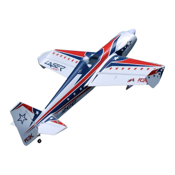
1980 World Championship tribute scheme and the modern Clint Sweet Designs “XA Scheme”, ensuring you stand out at the airfield. From its homage to the iconic lines of the Laser 200 to its championship-level prowess, this model stands as a testament to the spirit of innovation and excellence that defines Flex Innovations. -
Page 4: Specifications
QQ Cap 232EX / Laser 200 60E Aluminum Landing Gear (FPZDS38HVA, FPZDS38HVB) FPM447021 60-Size Battery Tray Thumb Screw Mamba / Cap 232 / Laser 200 60E Wheel Pant / Wheel Aura 8 Advanced Flight Control FPM397017 System (FPZAURA08 ) FPZMECO4120C-8... -
Page 5: Before You Begin
Use only compatible, appropriate components for the final assembly of this model. Ensure that the radio system is in functional condition, that the motor is appropriately sized for the model and that all other components are appropriate for use in this model as specified in this Laser 200 60E Instruction manual. -
Page 6: Safety Warnings And Precautions (Continued)
Our airplanes are designed around our Potenza LiPo batteries, and we recommend the Potenza 6S 4200mAh 40C LiPo in the Laser 200 60E based on our extensive testing and development. These batteries feature an EC5 connector, so no soldering is required for use in your Laser 200 60E. -
Page 7: Main Landing Gear Installation
MAIN LANDING GEAR INSTALLATION Required Tools and Fasteners: #1 Phillips Screwdriver (2) M3x10 Phillips Head Machine Screw 8mm Open End Wrench (4) M3x12 Phillips Head Self-Tapping Screw 12mm Open End Wrench (4) M3x15 Phillips Head Machine Screw Adjustable Wrench (optional) Blue Thread Lock (QTY 2) (QTY 4) -
Page 8: Vertical Fin Installation
VERTICAL FIN INSTALLATION Required Tools and Fasteners: #1 Phillips Screwdriver (1) M3x10 Phillips Head Self-Tapping Screw 30-Minute Epoxy Craft Sticks (for mixing epoxy) Paper Towels Mixing Cup Isopropyl Alcohol (QTY 1) 1. Dry fit the vertical fin to the fuselage. 2. -
Page 9: Tail Wheel Installation
TAIL WHEEL INSTALLATION Required Tools and Fasteners: #1 Phillips Screwdriver (3) M3x10 Phillips Head Self-Tapping Screw (QTY 3) 1. Insert the tail wheel into the slot in the bottom of the rudder. 2. Secure the retaining plate to the rudder fin using three M3x10 self tapping screws. -
Page 10: Horizontal Stabilizer Installation
HORIZONTAL STABILIZER INSTALLATION Required Tools and Fasteners: #1 Phillips Screwdriver (4) M2.6x8 Phillips Head Self-Tapping Screw (QTY 4) 1. Insert and roughly center the carbon fiber horizontal stabilizer tube in the fuselage. 2. Insert both halves of the horizontal stabilizer onto the tube. Ensure that the control horn faces the bottom of the fuselage and that the elevator jointer tabs line up properly. -
Page 11: Main Wing Installation
MAIN WING INSTALLATION Required Tools and Fasteners: (2) M4x18 Thumb Machine Screw #2 Phillips screwdriver (4) M5X35 Nylon Thumb Screws (QTY 2) (QTY 4) WARNING REMOVE THE AILERON SERVO HORN SCREWS AND APPLY BLUE THREAD LOCK TO THE SCREWS. RE-INSTALL THE SCREWS AND TIGHTEN FULLY. -
Page 12: Night Laser 200 60E Led Connections
NOTICE If you want to remotely switch the LEDs on your Night Laser 200 60E on or off then the LED controller should be plugged into port S6 in the Aura 8. If the servo lead of the LED controller is not plugged into the Aura, the LED controller will default to the ON position when powered. -
Page 13: Aura 8 Afcs
The Aura 8 AFCS (Advanced Flight Control System) comes programmed and pre-installed in your Laser 200 60E, making setup a breeze. This highly- refined 3-axis gyro makes the Laser 200 60E fly like it is a larger aircraft and in less wind. Thanks to the Aura’s advanced implementation, it not only enhances the flying experience, but it never interferes with the pilot’s control. -
Page 14: Transmitter Setup
Choosing a Receiver Aura will auto-detect modern serial receiver connections. For use in the Laser 200 60E, only a serial receiver connection can be used. Below are a few examples of serial receivers that can be used with the Aura 8. This is not a complete list of compatible receivers, rather a short list to assist in your receiver selection. -
Page 15: Connecting Your Receiver To Aura
Note: SRXL2 receivers like the 4651T or the AR6610T require the use of a different cable to connect to Aura. The cable is included with the receiver when it is purchased directly from Flex Innovations. You can also purchase the cable itself at flexinnovations.com (FPZA1039). -
Page 16: Rudder And Elevator Linkage Installation
RUDDER AND ELEVATOR LINKAGE INSTALLATION Required Tools and Fasteners: Elevator and Rudder Pushrod Assemblies #2 Phillips Screwdriver (4) M2x10 Phillips Head Machine Screw #0 Phillips Screwdriver (4) M2 Flat Washer Needle-Nosed Pliers (or Hemostats) (4) M2 Lock Nut Blue Thread Lock (4) M3x6 Phillips Head Machine Screw (QTY 4) (QTY 4) (QTY 4) -
Page 17: Rudder And Elevator Linkage Installation (Continued)
RUDDER AND ELEVATOR LINKAGE INSTALLATION (CONTINUED) 3. With the aircraft still powered on, install the rudder and elevator servo arms perpendicular to the servo case, being sure to orient the servo arm towards the bottom of the fuselage. Apply blue thread lock to the M3x6 Phillips head machine screw, and secure the servo arm in place with a #2 Phillips screwdriver. -
Page 18: Connecting Battery/Arming Esc
1. Power on your transmitter, DISABLE any throttle hold or throttle kill switches, completely lower the throttle trim and set the stick to full throttle. 2. Connect the flight pack to your Laser 200 60E. 3. Listen for the tones coming from the ESC through the motor, about 2 seconds after RF is engaged you should hear two tones. -
Page 19: Control Direction Test
CONTROL DIRECTION TEST Refer to the chart below to determine the proper control surface responses to transmitter control inputs. If controls are reversed, DO NOT REVERSE CONTROLS IN YOUR TRANSMITTER OR IN THE AURA CONFIG TOOL. Email us at support@flexinnovations.com for corrective action. Note that BOTH the Transmitter Control Direction Test AND the Flight Controller Sensor Direction Test MUST BE PASSED! IF EITHER ONE DOES NOT PASS, DO NOT FLY! NOTE: There is pre-configured rudder to aileron and rudder to elevator mixing programmed into the Aura. -
Page 20: Aura Sensor Direction Test
AURA SENSOR DIRECTION TEST Perform a test of the gyro system to verify the corrections made for a given movement are correct. If any of the tests do not result in the correct reaction from the airplane's gyro system, DO NOT FLY THE AIRPLANE, and contact us via email at support@flexinnovations.com The flight control system activates with RF broadcast. -
Page 21: Prop Adapter, Propeller And Spinner Installation
PROP ADAPTER, PROPELLER AND SPINNER INSTALLATION Required Tools and Fasteners: (5) M3X17 Propeller Adapter Bolts 2.5mm Hex Wrench M8 Nut & Washer for Propeller Adapter 13mm Wrench or Adjustable Wrench (1) M3x10 Phillips Button Head Screw #1 Phillips Screwdriver (QTY 1 ) (QTY 5) 1. -
Page 22: Battery Installation
CG. Setting the center of gravity is one of the most important steps for success, particularly with a new airplane. The Laser 200 60E is a high-performance airplane with large control surface throws, and a high thrust-to-weight ratio. These two factors combined make it a very enjoyable aircraft to fly, but if the CG is not within... -
Page 23: Pre-Flight Checklist
PRE-FLIGHT CHECKLIST To help ensure a successful first flight, as well as many flights after, perform a few simple pre-flight checks to be sure the aircraft is ready to fly: Verify the ailerons, elevators and rudder are properly hinged and in good working order. Pinch a control surface between your thumb and forefinger and grasp the wing/stabilizers with your other hand. -
Page 24: Laser 200 60E Aura Optional Features Configuration
LASER 200 60E AURA OPTIONAL FEATURES CONFIGURATION The Aura installed in your Laser 200 60E comes with the Quick Set feature. Quick Set allows the pilot to adjust options in the Aura without the use of a computer. The options of the Laser 200 60E are described below: •... -
Page 25: Flying Your Laser 200 60E
The airplane should lift off smoothly Power off the Laser 200 60E. Insert a bind plug into Aura Port S3 before the throttle is fully open. Fly in Flight Mode 1 until the aircraft is (you will need to remove the servo lead that is currently in S3). -
Page 26: Airframe Repairs
AIRFRAME REPAIRS The Laser 200 60E is molded from durable EPO foam and is repairable with most adhesives. Similar to building and repairing wood or composite airplanes, the correct glue for a given application is critical to the repair holding and not breaking again. For major repairs, such as a broken fuselage, epoxy is preferred because it allows time to correct any misalignment. -
Page 27: Aircraft Troubleshooting Guide
AIRCRAFT TROUBLESHOOTING GUIDE Should you encounter any abnormal situations with your Laser 200 60E, refer to the table below to determine the probable cause and a recommended solution for the issue. If the required solution does not rectify the problem, please contact product support at support@flexinnovations.com for further assistance. -
Page 28: Limited Warranty
LIMITED WARRANTY Questions & Assistance Warranty Coverage Contact Us By: Flex Innovations LLC and its authorized resellers (“Flex”) warrant to the E-Mail – support@flexinnovations.com original purchaser that this product (the “Product”) will be free from Phone – 1 (866) 310-3539 defects in materials and workmanship at the date of purchase. - Page 29 Building and Flying Notes...
- Page 30 Enjoy your Flex Innovations Laser 200 60E! w w w. f l e x i n n o v a t i o n s . c o m © 2024 Flex Innovations, LLC. All rights reserved. Potenza™ is a trademarks of Flex Innovations LLC DSM®, DSM2™, and DSMX™...
Need help?
Do you have a question about the LASER 200 and is the answer not in the manual?
Questions and answers