
Related Manuals for Mircom TX3-TOUCH-F15-B


Summary of Contents for Mircom TX3-TOUCH-F15-B
- Page 1 TX3 Series Touch Screen Installation Manual TX3 Touch Screen Installation Manual Version 4.2 1 (126) LT-996 Copyright February 2017...
- Page 2 It is subject to change without notice, and should not be construed as a commitment by Mircom. Mircom assumes no responsibility or liability for any errors or inaccuracies that appear in this book.
-
Page 3: Table Of Contents
Installing the Power Supply Enclosure Touch Screen System and Setup Touch Screen System TX3-TOUCH-K15-A, TX3-TOUCH-F15-A, TX3-TOUCH-S15-A Main Panel, Boards, and Grounding TX3-TOUCH-F15-B and TX3-TOUCH-S15-B Inside Door, Boards, and Grounding TX3-TOUCH-F22 and TX3-TOUCH-S22 Inside Door, Boards, and Grounding Telephone Access Controller Board... - Page 4 Contents 3.18 Installing a RB-MD-1093 Two Door Controller Network Board Adding Controllers Adding a Controller Specifications Operating Temperature Telephone Lines AC Power Supply 22” Touch Screen Power Consumption External Power Supply Door Strikes Outputs 2-4 Post Office Lock Tamper Switch 5.10 RS-485 TX3-USB-AD Kit 5.11...
- Page 5 List of Figures Figure 1 TX3 devices on an RS-485 network. Figure 2 TX3 devices connected to an Ethernet TCP/IP network. Devices connected to an Ethernet network are Master Nodes. Figure 3 TX3 devices connected to a combination Ethernet TCP/IP network with RS-485 subnetworks.
- Page 6 S15-B and TX3-TOUCH-F15-B with MD-1236 Figure 80 Factory connections on the PC sub compact board for TX3-TOUCH-S15-B and TX3-TOUCH-F15-B for MD-1236 Figure 81 Display connections on TX3-TOUCH-S15-B and TX3-TOUCH-F15-B for MD- 1236 Figure 82 Make sure that the arrow is visible Figure 83...
- Page 7 Figure 91 Factory connections on the PC sub compact board for TX3-TOUCH-S15-B and TX3-TOUCH-F15-B for MD-1105 Figure 92 Display connections on TX3-TOUCH-S15-B and TX3-TOUCH-F15-B Figure 93 Make sure that the arrow is visible Figure 94 Factory connections on the power supply and audio mixer board for TX3-...
-
Page 8: Introduction
• Resident Operating Instructions TX3 Systems The Mircom's TX3 series of Touch Screens provide high quality two-way communication between residents and their visitors in a multi-unit dwelling establishment. The basic TX3 system consists of the TX3 Touch Screen and depending on the application, may be integrated with a combination of Mircom Telephone Access, Card Access, and Elevator Restriction Units. - Page 9 1.1.3 Other Controllers Mircom devices, such as the Touch Screen and the Lobby Control Unit, can be networked with the TX3 system through a peer-to-peer RS-485 network, an Ethernet TCP/IP network, or a combination of an Ethernet network with RS-485 subnetworks.
-
Page 10: Figure 1 Tx3 Devices On An Rs-485 Network
Introduction any device on the RS-485 network (using USB, a modem, or the COM port), you can also connect to and configure any other device on the RS-485 network using the TX3 Configurator. Touch Screen Unit Elevator Restriction Unit Card Access Controller Card Reader A Card Reader B RS-485 Network... -
Page 11: Figure 2 Tx3 Devices Connected To An Ethernet Tcp/Ip Network. Devices Connected To An Ethernet Network Are Master Nodes
Introduction Ethernet TCP/IP network. If you connect directly to one of the Master Nodes using USB, a modem, or a COM port, you will be able to configure that device but not any other device. Touch Screen Unit Lobby Control Unit (Master Node) (Master Node) PQRS... -
Page 12: Figure 3 Tx3 Devices Connected To A Combination Ethernet Tcp/Ip Network With
Introduction Figure 3 shows a configuration with TX3 devices connected on both an Ethernet TCP/IP network and on RS-485 subnetworks. Devices connected to a Master Node’s RS-485 subnetwork are Slave Nodes to the Master Node. Each RS-485 subnetwork can have up to 63 devices connected to it; you can still have more than 63 Master Nodes connected to the Ethernet network. -
Page 13: Features
SWF, WMV and MPEG file formats • Fully removable lightweight inner chassis for easy maintenance • Industry Canada and F.C.C. approved Features of the TX3-TOUCH-S15-B and TX3-TOUCH-F15-B include: • 2000 name capacity • TCP/IP capability to remotely program and maintain the system TX3 Touch Screen Installation Manual Version 4.2... -
Page 14: Touch Screen Sizes And Enclosures
Introduction • Built-in HD web camera for video communication to the suite • Optional system diagnostic software for remote monitoring • Multi-language support; English and French are provided and a language editor allows all text to be translated into other languages •... -
Page 15: Touch Screen Accessories
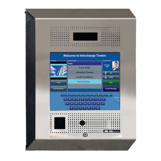
Designed for indoor use. Can be configured as a Master Node on an Ethernet network. TX3-TOUCH-F15-B. 15” Touch Screen flush mount, stainless steel finish Touch Screen with speaker, microswitch for postal lock, external MD-990 power supply, and flush mounting back box. -
Page 16: Mounting Requirements From The 2010 Ada Standards For Accessible Design
Introduction • TX3-T-KIOSK2: Black free standing square pillar mount for TX3- TOUCH-S15-B and TX3-TOUCH-S22 • TX3-T-KIOSK3: Black enclosed pillar mount for TX3-TOUCH-S22 • P1264 IP camera • TX3-GPM Guard Phone Module • Postal Lock • TX3-USB-AD Kit • TX3-CX-1NP Single Door Control Module, PoE, 12 VDC, 24-48 VDC Mounting requirements from the 2010 ADA Standards for Accessible Design See http://www.ada.gov/ for more information. -
Page 17: Warranty And Special Notices
Warranty and Special Notices Mircom values your business and always attempts to provide you with the very best service. Please see the Warranty and Special Notices chapter on page 120 for information about the warranty and special notices about equipment use. -
Page 18: Contact Us
TX3 Two Door Card Access System Kit Catalogue Number 6531 • TX3 Series Elevator Restriction Accessories Catalogue Number 6532 Contact Us Mircom fosters a collaborative support process and environment in providing early feedback to meet your specific needs. TX3 Touch Screen Installation Manual 18 (126) Version 4.2... -
Page 19: Technical Support
Toll-Free Fax: 1-888-660-4113 1.8.3 Website Visit the Mircom website, at www.mircom.com, to find the product information you are looking for and to learn about troubleshooting, training and technical support options. The website provides avenues for customers to ask questions about new and existing technologies, and receive expert technical support about software and products. -
Page 20: Enclosure Installation
This chapter explains • Installing TX3-TOUCH-S15-A - page 22 • Installing TX3-TOUCH-F15-A- page 25 • Installing TX3-TOUCH-F15-B - page 28 • Installing TX3-TOUCH-S15-B - page 30 • Installing TX3-TOUCH-S22 and TX3-TOUCH-F22 - page 32 • Installing TX3-T-KIOSK2 - page 43 •... -
Page 21: Installing The Enclosures And Touch Screen
Enclosure Installation Installing the Enclosures and Touch Screen The Touch Screen Kiosk, Surface Mount and Flush Mounts units consist of the following pre-assembled components: Kiosk. The kiosk is a pedestal mounted Touch Screen TX3-TOUCH-K15-A unit and consists of the following components: •... -
Page 22: Installing Tx3-Touch-S15-A
Enclosure Installation Installing TX3-TOUCH-S15-A 18.920 18.920 12.600 12.600 3.500 3.500 Figure 4. TX3-TOUCH-S15-A Surface Mount Back Dimensions (inches) TX3 Touch Screen Installation Manual 22 (126) Version 4.2 LT-996 Copyright 2017... -
Page 23: Figure 5 Tx3-Touch-S15-A Surface Mount Front Dimensions (Inches)
Figure 5. TX3-TOUCH-S15-A Surface Mount Front Dimensions (inches) The surface mount enclosure mounts on the wall. Mount the enclosure right-side up (the Mircom logo on the door is on the bottom). You need: • 6 fasteners appropriate for the wall that you are mounting the enclosure TX3 Touch Screen Installation Manual Version 4.2... -
Page 24: Figure 6 Touch Screen Surface Mount
Enclosure Installation Figure 6. Touch Screen Surface Mount To install the surface mount enclosure Find a suitable location for the enclosure. Using the enclosure as a template, mark the back mounting locations of the two keyholes as shown in Figure 6. Ensure that at least one side is over a wall stud. -
Page 25: Installing Tx3-Touch-F15-A
Enclosure Installation Installing TX3-TOUCH-F15-A 3.500 3.500 18.000 18.000 12.600 12.600 1.400 1.400 Figure 7. TX3-TOUCH-F15-A Flush Mount Back Dimensions (inches) TX3 Touch Screen Installation Manual Version 4.2 25 (126) LT-996 Copyright 2017... -
Page 26: Figure 8 Tx3-Touch-F15-A Flush Mount Front Dimensions (Inches)
Enclosure Installation 3.622 3.622 19.000 19.000 0.120 0.120 1.400 1.400 Figure 8. TX3-TOUCH-F15-A Flush Mount Front Dimensions (inches) The flush mount enclosure mounts directly inside the wall to the wall stud or supporting structure as shown in Figure 9. Mount the enclosure flush with the wall and right-side up (the knock out is at the bottom). -
Page 27: Figure 9 Flush Mount Enclosure
Enclosure Installation Wall Enclosure Frame Enclosure Front GROUND SCREW LOCATION Side View Figure 9. Flush Mount Enclosure To install the flush mount enclosure Find a suitable location for the enclosure. You can mount the enclosure using the keyholes on the back, or the knockouts on the side, or both. Using the enclosure as a template, trace an opening in the wall for the cutout with one side aligned with the side of the wall stud. -
Page 28: Installing Tx3-Touch-F15-B
63. Installing TX3-TOUCH-F15-B The flush mount enclosure mounts on the wall. Mount the enclosure right-side up (the Mircom logo on the door is on the bottom). You need: • 4 fasteners appropriate for the wall that you are mounting the enclosure on. -
Page 29: Figure 10 Tx-Touch-F15-B Dimensions
Enclosure Installation 3 31/32” 17 1/2” (101 mm) (445 mm) 3 51/64” (96 mm) 22” (559 mm) 1 1/4” (32 mm) Figure 10. TX-TOUCH-F15-B Dimensions 16 19⁄64” (414 mm) 12 19⁄32” (320 mm) 12 3/4” 17 9⁄16” (324 mm) (446 mm) 20 3/4”... -
Page 30: Installing Tx3-Touch-S15-B
Enclosure Installation Installing TX3-TOUCH-S15-B The surface mount enclosure mounts on the wall. Mount the enclosure right-side up (the Mircom logo on the door is on the bottom). You need: • 4 fasteners appropriate for the wall that you are mounting the enclosure on. -
Page 31: Figure 12 Tx-Touch-S15-B Dimensions
Enclosure Installation 3 31/32” (101 mm) 17 1/2” (445 mm) 70.00° 23 51/64” (604 mm) Figure 12. TX-TOUCH-S15-B Dimensions 16 19⁄64” (414 mm) 12 19⁄32” (320 mm) 12 3/4” (324 mm) 17 9⁄16” 20 3/4” (446 mm) (527 mm) 4 1/2” (114 mm) 2 7/32”... -
Page 32: Installing Tx3-Touch-S22 And Tx3-Touch-F22
Installing TX3-TOUCH-S22 The surface mount enclosure mounts on the wall. Mount the enclosure right-side up (the Mircom logo on the door is on the bottom). You need: 6 fasteners appropriate for the wall that you are mounting the enclosure on. - Page 33 The flush mount enclosure mounts directly inside the wall to the wall stud or supporting structure. Mount the enclosure flush with the wall and right-side up (the Mircom logo on the door is on the bottom). You need: 6 fasteners appropriate for the wall that you are mounting the enclosure on.
-
Page 34: Figure 15 Flush Mounting The Enclosure
Enclosure Installation If you are using the keyholes, remove the enclosure and place 2 fasteners halfway into the wall into the marked keyhole locations. Then place the enclosure onto the top fasteners and lower it so that the fasteners fit in the narrow part of the keyholes. -
Page 35: Figure 16 Tx3-Touch-F22 Dimensions (Inches)
Enclosure Installation Figure 16. TX3-TOUCH-F22 Dimensions (inches) TX3 Touch Screen Installation Manual Version 4.2 35 (126) LT-996 Copyright 2017... -
Page 36: Figure 17 Tx3-Touch-S22 Dimensions (Inches)
Enclosure Installation Figure 17. TX3-TOUCH-S22 Dimensions (inches) TX3 Touch Screen Installation Manual 36 (126) Version 4.2 LT-996 Copyright 2017... -
Page 37: Installing Tx3-T-Kiosk
Enclosure Installation Installing TX3-T-KIOSK 18.00 18.20 15.19 21.23 Figure 18. 22” Touch Screen Dimensions (inches) The Kiosk mounts to the floor inside the building near the entrance, close to the building power source and telephone infrastructure. Access for the power and communication cables is provided through a cutout in the base plate. -
Page 38: Figure 19 Components Of Tx3-T-Kiosk
Enclosure Installation • 6 #8-32 nuts for attaching the Touch Screen to the stand You will need: • 4 bolts to attach the base plate to the floor. The bolts need to fit holes that are 0.406” in diameter. Nuts (x6) Stand Screw cover (x8) Screw (x8) -
Page 39: Figure 20 Base Plate Mounting Holes
Enclosure Installation Using the base plate as a template, trace an opening on the floor for the cutout and mark the 4 base plate mounting hole locations as shown in Figure 20. Figure 20. Base Plate Mounting Holes Figure 21 shows the dimensions of the base plate. 14.244 Figure 21. -
Page 40: Figure 22 Fit The Stand On The Base Plate
Enclosure Installation To fit the TX3-T-KIOSK stand on the base plate Fit the back lip of the stand into the notches in the baseplate, and tilt the stand forwards so that it rests on top of the base plate. Figure 22. Fit the stand on the Base Plate Figure 23. -
Page 41: Figure 24 Attach The Stand To The Base Plate
Enclosure Installation Secure the stand onto the base plate using the screw cover bases, screws, and screw covers as show in Figure 24. Screw cover (x8) Screw (x8) Screw cover base (x8) Base plate Figure 24. Attach the stand to the base plate Attention: The 22”... -
Page 42: Figure 25 Attach The 22" Touch Screen To The Stand
Enclosure Installation Attach the six included screws to the posts. Hole for wiring Nuts (x6) Power and ground Figure 25. Attach the 22” Touch Screen to the stand Proceed with the power supply installation described in section 2.11 on page 63. TX3 Touch Screen Installation Manual 42 (126) Version 4.2... -
Page 43: Installing Tx3-T-Kiosk2
Enclosure Installation Installing TX3-T-KIOSK2 18” (457 mm) 15 3/16” (386 mm) 18 13/64” (462 mm) 22 3/16” (563 mm) Figure 26. Dimensions of TX3-T-KIOSK2 with TX3-TOUCH-S22 TX3 Touch Screen Installation Manual Version 4.2 43 (126) LT-996 Copyright 2017... -
Page 44: Figure 27 Dimensions Of Tx3-T-Kiosk2 With Tx3-Touch-S15-B
Enclosure Installation 17 1/2” (445 mm) 15 3/16” (386 mm) 18 13/64” (462 mm) 19 9/16” (497 mm) Figure 27. Dimensions of TX3-T-KIOSK2 with TX3-TOUCH-S15-B Note: TX3-TOUCH-S15-A can also be used with this stand. Attention: The stand is heavy. Never attempt to lift this product by yourself. -
Page 45: Figure 28 Components Of Tx3-T-Kiosk2
Enclosure Installation • 1 x floor bracket • 8 x screws for attaching the stand to the floor bracket • 8 x screw covers • 8 x screw bases • 6 x screws for attaching the Touch Screen to the stand Weight: 65.5 lb (30 kg) You need: •... -
Page 46: Figure 29 Tx3-T-Kiosk2 Dimensions (From Below)
Enclosure Installation Figure 29 shows the dimensions of the floor bracket. Front 7 1/8” (181 mm) 7 27/32” 9 5/8” (199 mm) (245 mm) Back Figure 29. TX3-T-KIOSK2 Dimensions (from below) Cut an opening in the floor for the electrical and communication cables. Run the wires through the floor bracket opening. -
Page 47: Figure 30 Fit The Stand On The Floor Bracket
Enclosure Installation Ensure that the floor bracket fits into the back lip of the stand.. Figure 30. Fit the stand on the floor bracket Figure 31. Fit the stand on the floor bracket (as seen from below) TX3 Touch Screen Installation Manual Version 4.2 47 (126) LT-996... -
Page 48: Figure 32 Attach The Stand To The Floor Bracket
Enclosure Installation Secure the stand onto the floor bracket using the screw cover bases, screws, and screw covers as show in Figure 32. Screw covers (x8) Screws (x8) Screw bases (x8) Figure 32. Attach the stand to the floor bracket To mount the Touch Screen on the stand Note: Use only surface mount Touch Screen (TX3-TOUCH-S22, TX3-... -
Page 49: Figure 33 Mounting Holes
Enclosure Installation Mount the 15” Mount the 22” Touch Screen on Touch Screen on holes 2 and 4. holes 1, 3 and 5. Figure 33. Mounting holes Figure 34. Mount TX3-TOUCH-S22 on the stand TX3 Touch Screen Installation Manual Version 4.2 49 (126) LT-996 Copyright 2017... -
Page 50: Figure 35 Mount Tx3-Touch-S15-B On The Stand
Enclosure Installation Figure 35. Mount TX3-TOUCH-S15-B on the stand TX3 Touch Screen Installation Manual 50 (126) Version 4.2 LT-996 Copyright 2017... -
Page 51: Installing Tx3-T-Kiosk3
Enclosure Installation Installing TX3-T-KIOSK3 61 11/32” (1558 mm) 15 1/4” (387 mm) 23 1/4” (591 mm) Figure 36. Dimensions of TX3-T-KIOSK3 Attention: The stand is heavy. Never attempt to lift this product by yourself. At least two people should lift it together. To ensure that there is enough room for installing the stand, leave at least 4”... -
Page 52: Figure 37 Components Of Tx3-T-Kiosk3
Enclosure Installation The kit includes: • 1 x pedestal • 1 x floor bracket • 1 x door • 6 x #8-32 x 1/4 screws for attaching the Touch Screen • 12 x #1/4-20 x 5/8 screws for attaching the stand to the floor bracket •... -
Page 53: Figure 38 Floor Bracket Mounting Holes
Enclosure Installation Using the floor bracket as a template, trace an opening on the floor for the cutout and mark the 6 floor bracket mounting hole locations as shown in Figure 38. Figure 38. Floor Bracket Mounting Holes Front 9” (228 mm) 8 11/64”... -
Page 54: Figure 40 Fit The Stand On The Floor Bracket
Enclosure Installation To fit the TX3-T-KIOSK3 stand on the floor bracket Attention: The stand is heavy. Never attempt to lift this product by yourself. At least two people should lift it together. It weighs 74 lb (34 kg). Fit the back lip of the stand into the notches in the floor bracket, and tilt the stand forwards so that it rests on top of the floor bracket. -
Page 55: Figure 42 Mount Tx3-Touch-S22 On The Stand
Enclosure Installation To fit the Touch Screen on the stand Attention: Use only the 22 inch flush mount Touch Screen (TX3-TOUCH- F22) with this stand. Attention: The 22” Touch Screen enclosure is heavy. Never attempt to lift this product by yourself. At least two people should lift it together. -
Page 56: Figure 43 Fit The Door On The Stand
Enclosure Installation To Attach the door Fit the door into the opening so that it rests on the ledge. Figure 43. Fit the door on the stand Figure 44. Close-up showing the door fitting on the ledge TX3 Touch Screen Installation Manual 56 (126) Version 4.2 LT-996... -
Page 57: Figure 45 Swing The Door Closed
Enclosure Installation Swing the door down and lock it. Figure 45. Swing the door closed Proceed with the power supply installation described in section 2.11 on page 63. TX3 Touch Screen Installation Manual Version 4.2 57 (126) LT-996 Copyright 2017... -
Page 58: Installing Tx3-Touch-K15-A
Enclosure Installation 2.10 Installing TX3-TOUCH-K15-A 17.950 14.187 Figure 46. Kiosk Dimensions (inches) The Kiosk mounts to the floor inside the building near the entrance, close to the power source and telephone infrastructure. Access for the power and communication cables is provided through a cutout in the base plate. To install the Kiosk you must: •... -
Page 59: Figure 47 Reinforcement Bracket With Bolts
Enclosure Installation To install the Touch Screen Kiosk base plate Find a suitable location for the Kiosk next to the building entrance and above the building electrical and communications conduit. Remove the door from the Kiosk. Remove the 4 bolts from the reinforcement bracket, as shown in Figure 47. Figure 47. -
Page 60: Figure 49 Kiosk Base Plate With Bolts
Enclosure Installation Remove the remaining 8 bolts that attach the Kiosk to the base plate, as shown in Figure 49. Figure 49. Kiosk Base Plate with bolts The 12 Kiosk mounting holes in the base plate are shown in Figure 50. Figure 50. -
Page 61: Figure 51 Base Plate Mounting Holes
Enclosure Installation Using the Kiosk base plate as a template, trace an opening in the floor for the cutout and mark the 4 base plate mounting hole locations as shown in Figure 51. Ensure that the base plate is aligned with the electrical conduit. Figure 51. -
Page 62: Figure 53 Fitting The Kiosk On The Base Plate
Enclosure Installation To fit the Touch Screen Kiosk on the base plate Fit the back lip of the Kiosk into the notches in the baseplate, and tilt the Kiosk forwards so that it rests on top of the base plate. Figure 53. -
Page 63: Installing The Power Supply Enclosure
Enclosure Installation Secure the Kiosk onto the base plate using the 8 of the 12 base plate bolts in the holes shown in Figure 55. Attach the Kiosk to the base plate with bolts in these holes first Figure 55. Attach the Kiosk to the base plate Position the reinforcement bracket over the 6 studs on the inside of the Kiosk, and screw the 6 nuts on to the studs as shown in Figure 48. -
Page 64: Figure 56 Inside The Switching Power Supply Box
Enclosure Installation Open the Switching Power Supply box using the key for the TX3 unit. The Switching Power Supply unit is secured inside the box by metal guides and two screws on either side of the terminal block. Unscrew and remove the screws on both sides of the terminal block. -
Page 65: Figure 58 Power Supply Enclosure Dimensions
Enclosure Installation The external power supply connects to the building power AC power supply. It is recommended that the unit is powered by its own dedicated electrical outlet to protect it from excessive power surges and current fluctuations. Note: Install the power supply outside the Touch Screen enclosure. Overall dimensions: height: 7 23/32”... -
Page 66: Figure 59 Power Supply Enclosure
Enclosure Installation Using the power supply enclosure as a template, mark the back mounting hole locations as indicated in Figure . Ensure that at least one side is over a wall stud. Remove the power supply enclosure and place the top two screws halfway into the marked hole locations and wall stud using the supplied screws. -
Page 67: Touch Screen System And Setup
This chapter explains • Touch Screen System • TX3-TOUCH-K15-A, TX3-TOUCH-F15-A, TX3-TOUCH-S15-A Main Panel, Boards, and Grounding • TX3-TOUCH-F15-B and TX3-TOUCH-S15-B Inside Door, Boards, and Grounding • TX3-TOUCH-F22 and TX3-TOUCH-S22 Inside Door, Boards, and Grounding • Telephone Access Controller Board •... -
Page 68: Touch Screen System
Touch Screen System and Setup Touch Screen System The TX3 Touch Screen may be networked with a combination of Telephone Access and Card Access Units through a peer-to-peer RS-485 connection. Touch Screen is capable of providing ADC or NSL telephone access from a single panel or from a networked system. -
Page 69: Figure 60 Single Touch Screen
Touch Screen System and Setup 3.1.1 Single Touch Screen Figure 60 shows the simplest configuration for an ADC or NSL telephone system. Telephone outlet Central office line Control Unit Line1 Line1 Touch Screen Touch Screen Figure 60. Single Touch Screen TX3 Touch Screen Installation Manual Version 4.2 69 (126) -
Page 70: Figure 61 Single Touch Screen With Adc And Nsl Lines
Touch Screen System and Setup Figure 61 shows a configuration using one Touch Screen connected to one ADC line and four NSL lines. Telephone outlet Central office line Control Control Control Control Unit Unit Unit Unit Line2 Line4 Line3 Line1 Line5 Touch Screen Figure 61. -
Page 71: Figure 62 15" Touch Screen Panel Components
Touch Screen System and Setup TX3-TOUCH-K15-A, TX3-TOUCH-F15-A, TX3- TOUCH-S15-A Main Panel, Boards, and Grounding 3.2.1 Main Panel On the Kiosk, the Touch Screen Panel is situated behind the front cover. To access the panel, unlock the Touch Screen and pull open the front cover. The 15”... -
Page 72: Figure 63 Controller Board Panel For 15" Touch Screens
Touch Screen System and Setup • Telephone Access Controller • PC Sub Compact Board • Power Supply Board • Audio Mixer Board To access the panel, remove the two screws and swing open the Touch Screen panel. Telephone Line PC Sub Compact Board Intranet Telephone Access... -
Page 73: Tx3-Touch-F15-B And Tx3-Touch-S15-B Inside Door, Boards, And Grounding
Touch Screen System and Setup TX3-TOUCH-F15-B and TX3-TOUCH-S15-B Inside Door, Boards, and Grounding 3.3.1 Inside Door The inside doors of TX3-TOUCH-F15-B and TX3-TOUCH-S15-B contain the following components as shown in Figure 64: • Speakers • Camera • Postal Lock (optional) •... -
Page 74: Figure 65 Controller Board Panel For Tx3-Touch-F15-B And Tx3-Touch-S15-B
PC Sub Compact Board Telephone Intranet Access Controller Power Supply and Audio Mixer Board On/Off USB Port for Keyboard On/Off Switch Figure 65. Controller Board Panel for TX3-TOUCH-F15-B and TX3-TOUCH-S15-B TX3 Touch Screen Installation Manual 74 (126) Version 4.2 LT-996 Copyright 2017... -
Page 75: Figure 66 Ground And Power Terminals
Figure 67. Power Terminals Ground Ground Screw Screw 16 Gauge Wire 16 Gauge Wire to Ground to Ground Figure 67. Grounding TX3-TOUCH-F15-B and TX3-TOUCH-S15-B TX3 Touch Screen Installation Manual Version 4.2 75 (126) LT-996 Copyright 2017... -
Page 76: Tx3-Touch-F22 And Tx3-Touch-S22 Inside Door, Boards, And Grounding
Touch Screen System and Setup TX3-TOUCH-F22 and TX3-TOUCH-S22 Inside Door, Boards, and Grounding The 22” Touch Screen inside doors contain the following components as shown in Figure 68: • Speakers • Camera • Postal Lock (optional) • Fan (optional) • Microphone •... -
Page 77: Figure 68 Tx3-Touch-F22 And Tx3-Touch-S22 Inside Door
Touch Screen System and Setup Speakers Camera Microphone Postal Lock Switch Postal Lock P300 Card Reader Keyhole Figure 68. TX3-TOUCH-F22 and TX3-TOUCH-S22 Inside Door 3.4.1 Controller Boards The 22” Touch Screen Panel contains the following components and controller boards as shown in Figure 69: •... -
Page 78: Figure 69 Controller Board Panel For Tx3-Touch-F22 And Tx3-Touch-S22
Touch Screen System and Setup • Power Supply and Audio Mixer Board To access the panel, unlock the door and swing it open. To access the power and ground terminals, remove the nut and open the cover at the bottom of the unit as shown in Figure 69. Telephone Line PC Sub Compact Board... -
Page 79: Figure 70 Grounding The 22" Touch Screen
Touch Screen System and Setup To ground the 22” Touch Screen Remove the nut and open the cover at the bottom of the unit as shown in Figure 69. Attach the ground screw to a suitable grounding wire and connect it to the site ground, as shown in Figure 70. -
Page 80: Telephone Access Controller Board
Touch Screen System and Setup Telephone Access Controller Board For detailed information about the Telephone Access Controller installation and setup see LT-969 TX3-Telephone Access System Installation and Operation Manual. Figure 71 shows the connectors at the top of the Telephone Access controller. Line 1 Line 5 General Relay... -
Page 81: Connecting To The External Power Supply
Touch Screen System and Setup Figure 72 shows the connectors at the bottom of the Telephone Access controller. Input 2 Input 3 Input 4 RS-485 OUT - s + LED/LAMP Supply Power Supply for TX3 Microphone Input 1 Input 5 (use 18 AWG) Connection Camera Supply... -
Page 82: Figure 73 Md-990 Terminal Block Wiring
Touch Screen System and Setup 3.6.1 Maximum Power Supply Wire Distances The distance from the Touch screen to the power supply is a function of the wire gauge and the resistance generated by the cable by the power draw. Do not exceed the maximum distances from the Touch screen to the power supply as indicated in Table 1. -
Page 83: Turning The Touch Screen On And Off
On TX3-TOUCH-K15-A, TX3-TOUCH-F15-A, TX3-TOUCH-S15-A, the power switch is on the outside of the door (Figure 62). On TX3-TOUCH-F15-B, TX3-TOUCH-S15-B, TX-TOUCH-F22, TX3- TOUCH-S22, the power switch is above the USB port (Figure 66 and Figure 69). TX3 Touch Screen Installation Manual Version 4.2... -
Page 84: Installing The Postal Lock
Touch Screen System and Setup Installing the Postal Lock The system has a built-in micro switch and mounting hardware for a postal lock installation. If postal service is required, contact the Post Office to obtain the lock. Note: When installing the postal lock leave the micro switch tie wrap in place. -
Page 85: Figure 74. Connecting Additional Rs-485 Terminal Connector To The First Or Last Node Of Network
+ (positive), - (negative), and S (Shield) connections. See Figure 74. 22 AWG twisted pair, maximum length: 4000 feet (1219.2 m) Mircom recommends shielded cable There are two additional RS-485 Terminal Connectors that must be added to the FIRST and LAST node of the network. -
Page 86: Verifying Installed Components
Touch Screen System and Setup 3.11 Verifying Installed Components Before turning on the system it is important to verify that the following connections are firmly in place. For additional information about the Telephone Access Controller Board Connectors see LT-969 TX3-Telephone Access System Installation and Operation Manual. -
Page 87: Figure 76 Md-1105
Touch Screen System and Setup On MD-1105 the button connector is on the top Figure 76. MD-1105 • If you have MD-1236, refer to section 3.12 on page 88. • If you have MD-1105, refer to section 3.13 on page 95. TX3 Touch Screen Installation Manual Version 4.2 87 (126) -
Page 88: Factory Wiring For Touch Screen Units With Md-1236
MD-1236 Sections 3.12.1 and 3.12.2 show the wiring for Touch Screen units with model MD-1236 of the power supply and audio mixer board. The diagrams include the Mircom part numbers of the cables (they begin with WX or WR). 3.12.1... -
Page 89: Figure 78 Wiring The Button
WX-110: TS1 on WX-109: TS12 MD-1236 on MD-1236 WX-030: Postal lock switch (optional) Figure 79. Factory connections on the telephone access controller board for TX3-TOUCH-S15-B and TX3-TOUCH-F15-B with MD-1236 TX3 Touch Screen Installation Manual Version 4.2 89 (126) LT-996 Copyright 2017... -
Page 90: Figure 80 Factory Connections On The Pc Sub Compact Board For Tx3-Touch-S15-B And Tx3-Touch-F15-B For Md-1236
Camera WX-079: P1 on MD-1236 WX-089: USB extension WX-057: Touch screen display Figure 80. Factory connections on the PC sub compact board for TX3-TOUCH-S15-B and TX3-TOUCH-F15-B for MD-1236 TX3 Touch Screen Installation Manual 90 (126) Version 4.2 LT-996 Copyright 2017... -
Page 91: Figure 81 Display Connections On Tx3-Touch-S15-B And Tx3-Touch-F15-B For Md
Touch Screen System and Setup WX-054: CN26 on PC WX-055: CN27 sub compact board on PC sub compact board WX-057: CN20 on PC sub compact board Figure 81. Display connections on TX3-TOUCH-S15-B and TX3- TOUCH-F15-B for MD-1236 Attention: The bottom cable must be connected so that the arrow is on the outside. -
Page 92: Figure 83 Factory Connections On The Power Supply And Audio Mixer Board (Md-1236) For Tx3-Touch-S22 And Tx3-Touch-F22
Touch Screen System and Setup 3.12.2 Factory Wiring for TX3-TOUCH-S22 and TX3-TOUCH-F22 with MD-1236 WX-079: CN31 on PC board WX-520: CN4 Black (ground) on PC board Red (clock) only if fan is White (data) WX-110: TS4 (bottom) present on telephone access controller TS4A TS6A... -
Page 93: Figure 85 Factory Connections On The Telephone Access Controller Board For Tx3-Touch
Touch Screen System and Setup WX-053: USB on PC board Power switch WX-077: Microphone WX-070: Ground wire to MD-1236 WX-110: TS1 on WX-109: TS12 MD-1236 on MD-1236 WX-030: Postal lock switch (optional) Figure 85. Factory connections on the telephone access controller board for TX3-TOUCH-S22 and TX3-TOUCH-F22 for MD- 1236 WR-21160 and... - Page 94 Touch Screen System and Setup CN32 on PC sub compact board WX-082: USB extension on PC sub compact board MD-1256: TS10B on MD-1236 Figure 87. Display connections on TX3-TOUCH-S22 and TX3- TOUCH-F22 for MD-1236 TX3 Touch Screen Installation Manual 94 (126) Version 4.2 LT-996 Copyright 2017...
-
Page 95: Factory Wiring For Touch Screen Units With Md-1105
MD-1105 Sections 3.13.1 and 3.13.2 show the wiring for Touch Screen units with model MD-1105 of the power supply and audio mixer board. The diagrams include the Mircom part numbers of the cables (they begin with WX or WR). 3.13.1... -
Page 96: Figure 89 Wiring The Button
WX-110: TS1 on WX-109: TS8 on MD-1105 MD-1105 Postal lock switch (optional) Figure 90. Factory connections on the telephone access controller board for TX3-TOUCH-S15-B and TX3-TOUCH-F15-B for MD-1105 TX3 Touch Screen Installation Manual 96 (126) Version 4.2 LT-996 Copyright 2017... -
Page 97: Figure 91. Factory Connections On The Pc Sub Compact Board For Tx3-Touch-S15-B And Tx3-Touch-F15-B For Md-1105
Camera WX-079: P1 on MD-1105 WX-089: WX-057: USB extension Touch screen display Figure 91. Factory connections on the PC sub compact board for TX3-TOUCH-S15-B and TX3-TOUCH-F15-B for MD-1105 TX3 Touch Screen Installation Manual Version 4.2 97 (126) LT-996 Copyright 2017... -
Page 98: Figure 92 Display Connections On Tx3-Touch-S15-B And Tx3-Touch-F15-B
Touch Screen System and Setup WX-054: CN26 on PC WX-055: CN27 sub compact board on PC sub compact board WX-057: CN20 on PC sub compact board Figure 92. Display connections on TX3-TOUCH-S15-B and TX3- TOUCH-F15-B Attention: The bottom cable must be connected so that the arrow is on the outside. -
Page 99: Figure 94 Factory Connections On The Power Supply And Audio Mixer Board For Tx3- Touch-S22 And Tx3-Touch-F22
Touch Screen System and Setup 3.13.2 Factory Wiring for TX3-TOUCH-S22 and TX3-TOUCH-F22 with MD-1105 WX-079: CN31 on PC board WX-081: CN1 on PC board SW-207: Button WX-110: TS4 (bottom) on telephone access controller WX-520: CN4 Black (ground) WR-12223 and WR-12224: on PC board TS11 Red (clock) -
Page 100: Figure 96. Factory Connections On The Telephone Access Controller Board For Tx3-Touch-S22 And Tx3-Touch-F22 For Md-1105
Touch Screen System and Setup WX-053: USB on PC board Power switch ON WX-077: Microphone WX-070: Ground wire to MD-1236 WX-110: TS1 on WX-109: TS8 on MD-1105 MD-1105 Postal lock switch (optional) Figure 96. Factory connections on the telephone access controller board for TX3-TOUCH-S22 and TX3-TOUCH-F22 for MD-1105 WR-21160 and... -
Page 101: Beginning Configuration
Touch Screen System and Setup CN32 on PC sub compact board USB extension on PC sub compact board MD-1117: TS6 on MD-1105 Figure 98. Display connections on TX3-TOUCH-S22 and TX3- TOUCH-F22 3.14 Beginning Configuration Ensure that the Telephone Access Controller ID is setup. This address is set by the SW1 DIP switches on the Telephone Access Controller (Figure 63). -
Page 102: Installing The P1264 Ip Camera
LT-973 TX3 Configurator Quick Start 3.15 Installing the P1264 IP camera You can install a P1264 IP camera in TX3-TOUCH-F15-B, TX3-TOUCH-S15-B, and the 22” Touch Screen. To install the IP camera Shut down the Touch Screen and disconnect the power. -
Page 103: Figure 100 Mounting The Ip Camera In The Bracket
Touch Screen System and Setup Mount the camera on two posts and secure it with the included nuts. Nuts IP camera Bracket Figure 100.Mounting the IP camera in the bracket The camera bracket can be mounted in the door in three ways. Mount the bracket as shown in Figure 101 with the nuts on top so that the camera faces down. -
Page 104: Replacing The Display On The 22" Touch Screen
Touch Screen System and Setup Mount the bracket as shown in Figure 102 with the nuts on bottom so that the camera faces up Put nuts here to face the camera upwards Figure 102.Mounting the camera bracket upside down Connect the IP camera according to the manufacturer’s instructions. 3.16 Replacing the Display on the 22”... -
Page 105: Figure 103 Inside Of Door Showing Position Of The Four #6-32 Nuts
Touch Screen System and Setup Remove the four #6 nuts and keep them. Figure 103.Inside of door showing position of the four #6-32 nuts Remove the display from the four posts. TX3 Touch Screen Installation Manual Version 4.2 105 (126) LT-996 Copyright 2017... -
Page 106: Figure 104 The Two Brackets (Ch-1165) Holding The Display
Touch Screen System and Setup Remove the eight M4x8mm screws and the outside brackets (CH-1165). Keep the brackets and the screws. Figure 104.The two brackets (CH-1165) holding the display To attach the new display Attach the supplied 3M brackets to the display using the supplied M4 screws. -
Page 107: Figure 105 Power Button
Touch Screen System and Setup Slide the display on to the four posts on the door and secure the four #6 nuts on the posts. Note: Make sure to install the display the right way up. The four buttons should be on the bottom. Adjust the screen so that it is flush with the front of the door panel, and then tighten the 8 M4x8mm screws. -
Page 108: Installing The Tx3-P300-Ha Card Reader In The 22" Touch Screen
Touch Screen System and Setup 3.17 Installing the TX3-P300-HA Card Reader in the 22” Touch Screen Open the Touch Screen door. Install the fan in the lower left corner of the door, as shown in Figure 106. TX3-P300-HA Card Reader Figure 106.Position of the TX3-P300-HA Card Reader TX3 Touch Screen Installation Manual 108 (126) -
Page 109: Figure 107 The Tx3-P300-Ha Card Reader
Touch Screen System and Setup Attach the card reader to the 2 posts on the bracket with the 2 #4-40 nuts as shown in Figure 107. TX3-P300-HA Bracket Posts(x2) Card Reader Nuts (x2) Figure 107.The TX3-P300-HA Card Reader Slide the bracket on to the 4 posts on the Touch Screen door and secure it with the 4 #8-32 nuts as shown in Figure 108. -
Page 110: Installing A Rb-Md-1093 Two Door Controller Network Board
Touch Screen System and Setup 3.18 Installing a RB-MD-1093 Two Door Controller Network Board Refer to the manual LT-981A that came with the two door controller network board for instructions on how to install it. TX3 Touch Screen Installation Manual 110 (126) Version 4.2 LT-996... -
Page 111: Adding Controllers
Adding Controllers This chapter provides information about adding additional controllers on the same network as the Touch Screen. This chapter explains • How to add the controller Attention: If you use the TX3-MDM Modem Module to connect to and configure a Touch Screen, then you cannot configure the Touch Screen locally. -
Page 112: Adding A Controller
Adding Controllers Adding a Controller The TX3 Touch Screen may be integrated with other controllers, such as the Telephone and Card Access systems, through a peer-to-peer connection via the RS-485 bus. Touch has a provision to add the TX3 Card Access controller inside the unit. Note: Ensure that all network devices each have unique ID addresses. -
Page 113: Specifications
MD-990 156 W, 24 V single output switching power supply. Door Strikes Select the appropriate door strike as required by your system applications. We recommend using the following Mircom door strikes below and its compatible power transformer. TX3 Touch Screen Installation Manual Version 4.2... -
Page 114: Outputs
Specifications • Mircom Model M-10. DC (silent) or AC (buzzing) Door Strike. (Use PS- 3B transformer) Note: The door strike must have its own separate power transformer. Do not tap or use the system power transformers. When using a different door strike and door strike transformer, the maximum strike load that may be switched through the control unit is 28 VAC or 1 Amp DC. -
Page 115: Tx3-Gpm Guard Phone Module
Specifications 5.11 TX3-GPM Guard Phone Module The guard phone connects via a telephone cable to the Guard Phone Module on the Touch Screen. The TX3-GPM Guard Phone Module mounts on the TX3 Telephone controller board. For installation instructions see LT-972 TX3-GPM Guard Phone Module Installation Instructions. -
Page 116: Resident Operating Instructions
Resident Operating Instructions This chapter describes the Touch Screen operating instructions for use by the resident. This chapter explains • NSL Resident Operating Instructions • ADC Resident Operating Instructions TX3 Touch Screen Installation Manual 116 (126) Version 4.2 LT-996 Copyright 2017... -
Page 117: Nsl Resident Operating Instructions
Resident Operating Instructions NSL Resident Operating Instructions Mircom's state-of-the-art Touch Screen door entry system provides you and your guest with an increased level of confidence and security. Touch Screen operates with your existing telephone. Your guest dials your code number or selects your name by scrolling through the visual directory on the Touch Screen unit, causing your telephone to ring. - Page 118 Resident Operating Instructions 6.1.3 Call Waiting Feature When a guest places a call to you from the Touch Screen while you are engaged in a conversation on your outside telephone line, you will hear a distinct tone. To answer the call Briefly push the call waiting key to answer the call.
-
Page 119: Adc Resident Operating Instructions
Resident Operating Instructions ADC Resident Operating Instructions Mircom's state-of-the-art Touch Screen door entry system provides you and your guest with an increased level of confidence and security. Touch Screen operates with your existing telephone. Your guest dials your code number or selects your name by scrolling through the visual directory on the Touch Screen unit, causing your telephone to ring. -
Page 120: Warranty & Warning Information
During the warranty period, Mircom shall, at its option, repair or replace any defective product upon return of the product to its factory, at no charge for labour and materials. -
Page 121: Out Of Warranty Repairs
Mircom neither assumes nor authorizes any other person purporting to act on its behalf to modify or to change this warranty, nor to assume for it any other warranty or liability concerning this product. - Page 122 Products which Mircom determines to be repairable will be repaired and returned. A set fee which Mircom has predetermined and which may be revised from time to time, will be charged for each unit repaired. Products which Mircom determines not to be repairable will be replaced by the nearest equivalent product available at that time.
-
Page 123: Special Notices
Special Notices Product Model Number: TX3 AC REN (U.S.): 0.0B AC REN (CANADA): 0.0 Complies With Federal Communications Commission (FCC): • TIA-968-A Technical requirement for connection of equipment tot he telephone network. • CFR 47, Part 15, Subpart B, Class B •... - Page 124 Repairs to certified equipment should be made by an authorized Canadian maintenance facility designated by the supplier. Any repairs or alteration made by the user to this equipment, or equipment malfunctions, may give the telecommunications company cause to request the user to disconnect the equipment.
-
Page 125: Tx3 Touch Screen Installation Manual Version 4.2 Lt-996 Copyright
Contact your telephone company if you have any questions about your telephone line. In the event repairs are ever needed on the Communicator, they should be performed by Mircom or an authorized representative of Mircom. For information contact Mircom at the address and telephone numbers in paragraph 1.8. -
Page 126: Telephone Connection
Equipment Failure If trouble is experienced with the TX3 Telephone/Card Access System, for repair or warranty information, please contact Mircom using the numbers paragraph 1.8. If the equipment is causing harm to the telephone network, the telephone company may request that you disconnect the equipment until the problem is resolved.
Need help?
Do you have a question about the TX3-TOUCH-F15-B and is the answer not in the manual?
Questions and answers