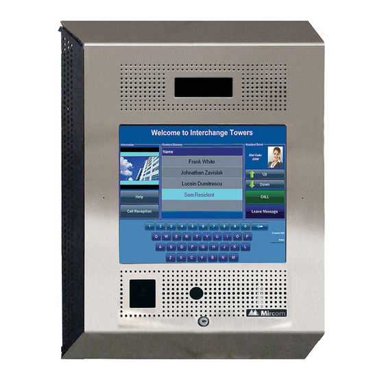
Mircom TX3-TOUCH-F15-B Assembly Manual
Hide thumbs
Also See for TX3-TOUCH-F15-B:
- Installation manual (126 pages) ,
- Installation manual (161 pages)
Advertisement
Quick Links
17 1/2"
(445 mm)
22"
(559 mm)
1 1/4"
(32 mm)
16 19⁄64"
(414 mm)
12 19⁄32"
(320 mm)
12 3/4"
17 9⁄16"
(324 mm)
(446 mm)
20 3/4"
(527 mm)
4 1/2"
(114 mm)
2 7/32"
(57 mm)
For more details, see LT-996 and LT-969 on the Mircom website and the USB fl ash.
Mircom technical support: 1-888-647-2665
Mount the
1
3 31/32"
Enclosure
(101 mm)
3 51/64"
(96 mm)
The enclosure mounts on the wall. Mount the
enclosure right-side up (the Mircom logo on the
door is in the lower right corner).
You need:
4 fasteners appropriate for the wall that you are
mounting the enclosure on.
1. Find a suitable location for the enclosure. You can
mount the enclosure using the keyholes on the
back, or the knockouts on the side, or both.
2. Trace an opening in the wall for the enclosure
with one side aligned with a wall stud.
2. Cut an opening in the wall 3/32" (3 mm) larger
than the tracing, ensuring that one side is
aligned with the wall stud or supporting
structure.
3. Insert the enclosure into the wall cutout, and
using the side of the enclosure as a template
mark the hole mounting locations (either
keyholes or knockouts or both).
4. If you are using the keyholes, remove the
enclosure and place 2 fasteners halfway into the
wall into the two top keyhole locations.
5. Place the enclosure onto the top fasteners, then
lower it so that the fasteners fi t in the narrow
part of the keyholes.
6. Screw the other fasteners into the remaining
holes.
7. Tighten all fasteners into place.
Warning: Turn the power
off before wiring.
Install all power supplies outside the enclosure.
Wiring Requirements
Unless specifi ed otherwise, all wiring is a maximum
length of 1000 ft (304.8 m).
RS-485: 22 AWG twisted pair, maximum length: 4000
ft (1219.2 m). Mircom recommends shielded cable.
Door Strike: The door strike power supply depends
on the door strike power requirements.
AC or DC Door
Auxiliary Door
1
Strikes:
Strike:
4
see
2
and
3
see
NO
NC
Jumper JW8
NO
NC
Jumper JW8
SW1
DIP Switches:
see
5
Camera Supply:
see
6
Maximum Power Supply Wire Distances
Gauge
Distance
16
125 ft (38.1 m)
14
200 ft (60.96 m)
12
320 ft (97.536 m)
10
500 ft (152.4 m)
ASSEMBLING TX3-TOUCH-F15-B
AC Door Strike or Maglock
2
18 AWG
AC Door Strike or
Magnetic Lock
AC or DC Power
AC Power Supply
Supply for Door
for Door Strike
Strike
TS8
For a door strike: connect the
jumper wire to the top pin of
jumper JW8 (normally open).
For a maglock: connect the
jumper wire to the bottom
The maximum supply for the AC or DC
pin of jumper JW8 (normally
Power Supply for Door Strike must not
closed).
exceed:
28 VAC / 1 A max
30 VDC / 1 A max
Auxiliary Door
4
(Output 2)
18 AWG
-
Jumper JW8
Door Strike
TS9
Note: Most door
NO
strikes are non-
NC
+
polarity.
+
-
Power Supply
Note: If AC power
supply is used,
polarity does not
apply.
DIP Switch Settings
5
for RS-485 Address
Address 1
Address 2
Address 3
Address 4
ON
OFF
1
8
1
8
1
8
1
8
Each Touch Screen must have a unique RS-485
address.
Use DIP switches 1-6 to set the RS-485 network
address. See LT-969 for details.
DC Door Strike
3
(Output 1)
18 AWG
DC Output
Door Strike or
Magnetic Lock
TS8
TS9
Alternative Wiring
for Dry Contact
Trigger for door operator
Jumper JW8 controls
TS8
whether the contact
is normally open or
normally closed.
Contact ratings for outputs 2-4:
125 VAC / 2 A
30 VDC / 1 A
6
Camera Supply
TS3
Camera Power
Supply (12 VDC)
© Mircom 2015
Printed in Canada
Subject to change without prior notice
LT-6125 rev 0
Advertisement

Related Manuals for Mircom TX3-TOUCH-F15-B


Summary of Contents for Mircom TX3-TOUCH-F15-B
-
Page 1: Dip Switch Settings
Supply (12 VDC) © Mircom 2015 For more details, see LT-996 and LT-969 on the Mircom website and the USB fl ash. Printed in Canada Mircom technical support: 1-888-647-2665 Subject to change without prior notice... -
Page 2: Power Supply
(Outputs 1 and 2). (16 AWG) (905) 647-2665 © Mircom 2015 For more details, see LT-996 and LT-969 on the Mircom website and the USB fl ash. Printed in Canada Mircom technical support: 1-888-647-2665 Subject to change without prior notice...
Need help?
Do you have a question about the TX3-TOUCH-F15-B and is the answer not in the manual?
Questions and answers