Table of Contents
Advertisement
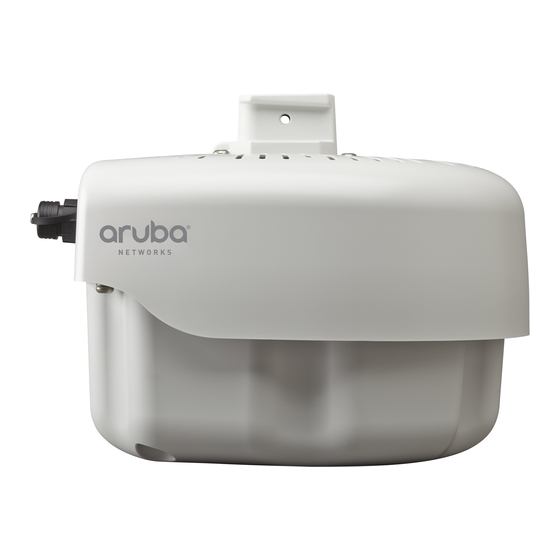
AP-270 Series Outdoor Access Point
Installation Guide
The Aruba AP-274 and AP-275 are environmentally hardened, outdoor rated, dual-radio IEEE 802.11ac
wireless access points. These access points use MIMO (Multiple-in, Multiple-out) technology and other
high-throughput mode techniques to deliver high-performance, 802.11ac 2.4 GHz and 5 GHz functionality
while simultaneously supporting existing 802.11a/b/g/n wireless services. The AP-270 Series access point
works only in conjunction with an Aruba Controller.
AP-270 Series Operations
Wireless transceiver
Wireless access point (IEEE 802.11 a/b/g/n/ac)
Wireless air monitor (IEEE 802.11 a/b/g/n/ac)
Protocol-independent networking functionality
Compatibility with IEEE 802.3at PoE
Central management configuration and upgrades with an Aruba Controller.
Guide Overview
"AP-270 Series Hardware Overview" on page 3
AP-275.
"Before You Begin" on page 7
outdoor wireless network.
"Installing the AP" on page 9
deployment of the AP-274 and AP-275.
"Safety and Regulatory Compliance" on page 21
compliance information.
Package Contents
AP-274 or AP-275 Access Point
Cable Glands x2
Copper Lug x1
M4x6 Screw x1
USB Console Cable
Installation Guide (this document)
The weatherproof caps for Ethernet, Console, and power interfaces are connected to the AP, not loose in the
package.
Mounting kits for use with the AP-270 Series access points are sold separately. Contact your Aruba sales
representative for details.
0511511-05
| February 2014
provides a detailed hardware overview of the AP-274 and
provides key questions to ask and items to consider when deploying an
describes the multi-step process for a successful installation and
provides an overview of safety and regulatory
1
Advertisement
Table of Contents

Subscribe to Our Youtube Channel
Related Manuals for Aruba AP-274


Summary of Contents for Aruba AP-274
-
Page 1: Package Contents
The weatherproof caps for Ethernet, Console, and power interfaces are connected to the AP, not loose in the package. Mounting kits for use with the AP-270 Series access points are sold separately. Contact your Aruba sales representative for details. 0511511-05... - Page 2 Inform your supplier if there are any incorrect, missing, or damaged parts. If possible, retain the carton, including the original packing materials. Use these materials to repack and return the unit to the supplier if needed. AP-270 Series Outdoor Access Point | Installation Guide...
-
Page 3: Ap-270 Series Hardware Overview
Figure 2 AP-274 Front View (Aesthetic Cover Removed) System LED The antenna connectors of AP-274 are covered by an aesthetic cover in the package. The aesthetic cover can be removed when necessary. The AP-270 Series is equipped with one LED that indicates the system status of the AP. - Page 4 Table 1 AP-270 Series LED Meanings during Boot Up Color/State Meaning System LED No power to AP Initial power-up Green - Flashing AP booting Green - Steady AP ready and 1000Mbps Ethernet link established. The LED turns off after 1200 seconds Green - Yellow, 6 seconds AP ready and 10/100Mbps Ethernet link established.
- Page 5 Figure 4 AP-274 Rear View Grounding Point USB Console Port and Reset button AC Power Interface LAN Port WAN Port USB Console Port The USB Micro-B console port allows you to connect the AP to a terminal or a laptop for direct local management.
- Page 6 AP enclosure. Figure 6 AP-275 Top View Mounting Holder Solar Shield Figure 7 AP-274 Top View Mounting Holder Solar Shield At the top of the AP-270 Series, the solar shield with the mounting holder is fixed onto the AP before shipping from the factory.
-
Page 7: Before You Begin
Figure 9 AP-274 bottom View Air Vent External Antenna Connectors The AP-274 is equipped with six external antenna connectors. The connectors are labeled 2G0, 2G1, 2G2, 5G0, 5G1 and 5G2, and correspond to 2.4/5Ghz radio chains 0,1, and 2. Air Vent The bottom of the AP-270 Series has an air vent to balance the pressure and humidity inside and outside the AP. -
Page 8: Pre-Installation Network Requirements
After WLAN planning is complete and the appropriate products and their placement have been determined, the Aruba controller(s) must be installed and initial setup performed before the Aruba APs are deployed. For initial setup of the controller, refer to the ArubaOS Quick Start Guide for the software version installed on your controller. -
Page 9: Installing The Ap
You can mount the AP-270 Series access point on a wall or pole. Use the AP placement map generated by Aruba’s RF Plan software application to determine the proper installation location(s). Each location should be as close as possible to the center of the intended coverage area and should be free from obstructions or obvious sources of interference. - Page 10 Figure 10 Mounting Bracket (AP-270-MNT-V1) To install Figure 11 Mounting Bracket (AP-270-MNT-V2) To install Mounting the AP to a Wall 1. Begin by marking the mounting points on the wall in the location you have selected. a. Put the mounting bracket (included in the mount kit) on the installation position against the wall. b.
- Page 11 Figure 13 Attaching the Mounting Bracket (AP-270-MNT-V2) to a Wall 6. Slide the holder of the AP into the opening of the bracket and use the two screws to fix the holder as shown in Figure 14 Figure Figure 14 Attaching the AP to the Mounting Bracket (AP-270-MNT-V1) AP-270 Series Outdoor Access Point | Installation Guide...
- Page 12 Figure 15 Attaching the AP to the Mounting Bracket (AP-270-MNT-V2) 7. Use the cable tie to fasten the cables on the bracket. 8. On the AP-274, install the external antennas according to the manufacturer’s instructions, and connect the antennas to the antenna interfaces on the AP.
- Page 13 Figure 16 Mounting the Mounting Bracket (AP-270-MNT-V2) to the Corner Mount Adaptor 3. Slide the holder of the AP into the opening of the bracket and use the two screws to fix the holder as shown in Figure Figure 17 Attaching the AP to the Mounting Bracket (AP-270-MNT-V2) 4.
- Page 14 5. On the AP-274, install the external antennas according to the manufacturer’s instructions, and connect the antennas to the antenna interfaces on the AP. Mounting the AP to a Vertical Pole The mounting bracket provides different slots for pole mounting according to the diameter and shape of the...
- Page 15 Figure 20 Attaching the AP to the Mounting Bracket (AP-270-MNT-V1) AP-270 Series Outdoor Access Point | Installation Guide...
-
Page 16: Grounding The Ap
Figure 21 Attaching the AP to the Mounting Bracket (AP-270-MNT-V2) 3. Use the cable tie to fasten the cables on the bracket. 4. On the AP-274, install the external antennas according to the manufacturer’s instructions, and connect the antennas to the antenna interfaces on the AP. -
Page 17: Connecting The Ethernet Cable
Connecting the Power Cable Installation and service of Aruba products should be performed by Professional Installers in a manner that is consistent with the electrical code in force in the jurisdiction of deployment. In many countries this will require a licensed electrician to perform this operation. - Page 18 The applicable SKUs for these options are: Table 4 SKUs for Powering Options Part Number Description PC-OD-AC-P-NA Weatherproof AC power cable(5m), North America version PC-OD-AC-P-INT Weatherproof AC power cable(5m), International (EU) version CKIT-OD-AC-P Weatherproof connector kit for AC power interface The difference between the NA and INTL part variants is the color coding of the conductors.
-
Page 19: Verifying Post-Installation Connectivity
Provisioning parameters are unique to each AP. These local AP parameters are initially configured on the controller which are then pushed out to the AP and stored on the AP itself. Aruba recommends that provisioning settings be configured via the ArubaOS Web UI only. Refer to the ArubaOS User Guide for complete details. -
Page 20: Product Specifications
Mechanical: Device Dimensions (HxWxD) AP-274 (without aesthetic cover): 5.5 inches x 9 inches x 9.4 inches (14cm x 23cm x 24cm) AP-274 (with aesthetic cover): 7.5 inches x 9 inches x 9.4 inches (19cm x 23cm x 24cm) ... -
Page 21: Safety And Regulatory Compliance
Safety and Regulatory Compliance Aruba Networks provides a multi-language document that contains country-specific restrictions and additional safety and regulatory information for all Aruba access points. This document can be viewed or downloaded from the following location: www.arubanetworks.com/safety_addendum Regulatory Model Name... -
Page 22: Proper Disposal Of Aruba Equipment
Waste of Electrical and Electronic Equipment Aruba products at end of life are subject to separate collection and treatment in the EU Member States, Norway, and Switzerland and therefore are marked with the symbol shown at the left (crossed-out wheelie bin). The treatment applied at end of life of these... -
Page 23: Canadian Statement
Hazardous Materials Declaration (Hazardous Substance) (Parts) PCA Boards) Mechanical Sub-Assemblies) SJ/T11363-2006 Indicates that the concentration of the hazardous substance in all homogeneous materials in the parts is below the relevant threshold of the SJ/T11363-2006 standard. Indicates that the concentration of the hazardous substance of at least one of all homogeneous materials in the parts is above the relevant threshold of the SJ/T11363-2006 standard. - Page 24 Caution: This radio transmitter (identify the device by certification number, or model number if Category II) has been approved by Industry Canada to operate with the antenna types listed below with the maximum permissible gain and required antenna impedance for each antenna type indicated. Antenna types not included in this list, having a gain greater than the maximum gain indicated for that type, are strictly prohibited for use with this device.
-
Page 25: Contacting Aruba Networks
VPN client devices constitutes complete acceptance of liability by that individual or corporation for www.arubanetworks.com this action and indemnifies, in full, Aruba Networks, Inc. from any and all legal actions that might be taken against it with respect to infringement of copyright on behalf of those vendors.
Need help?
Do you have a question about the AP-274 and is the answer not in the manual?
Questions and answers