Table of Contents
Advertisement
Quick Links
Download this manual
See also:
Instruction Manual
SERVICE MANUAL
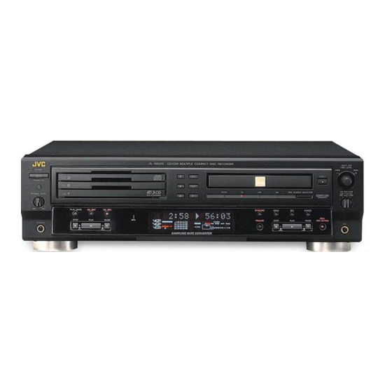
CD/CDR MULTIPLE COMPACT DISC RECORDER
STANDBY/ON
CD1
CD2
CD3
1
2
3
4
5
6
7
8
9
10
10
GROUP
CONTROL
PLAY
MODE
REPEAT
CD
CDR
GROUP
SET
GROUP
CD REC CD EDIT SYNCHRO
FADE
MIN
MAX
REC
FINALIZE
PITCH 0
REC MUTING
PITCH
RM-SXL001J
REMOTE CONTROL
XL-R5020BK
XLÐR5020 CD/CDR MULTIPLE COMPACT DISC RECORDER
COMPACT
DIGITAL AUDIO
MP3 PLAYBACK
COPYRIGHT
2002 VICTOR COMPANY OF JAPAN, LTD.
Area Suffix
J ------------- U.S.A.
COMPACT
DIGITAL AUDIO
Recordable
ReWritable
XL-R5020BK
No.A0035
Aug. 2002
Advertisement
Chapters
Table of Contents

Related Manuals for JVC XL-R5020BK


Summary of Contents for JVC XL-R5020BK
- Page 1 XL-R5020BK SERVICE MANUAL CD/CDR MULTIPLE COMPACT DISC RECORDER XL-R5020BK Area Suffix J ------------- U.S.A. STANDBY/ON GROUP CONTROL PLAY MODE REPEAT GROUP XLÐR5020 CD/CDR MULTIPLE COMPACT DISC RECORDER GROUP COMPACT COMPACT DIGITAL AUDIO DIGITAL AUDIO Recordable ReWritable CD REC CD EDIT SYNCHRO...
-
Page 2: Table Of Contents
XL-R5020BK TABLE OF CONTENTS Important Safety Precautions ............. 3 Safety Precautions . -
Page 3: Important Safety Precautions
XL-R5020BK SECTION 1 Important Safety Precautions 1.1 Safety Precautions (1) This design of this product contains special hardware and voltmeter. many circuits and components specially for safety purposes. Move the resistor connection to each exposed metal part, For continued protection, no changes should be made to the... -
Page 4: Preventing Static Electricity
XL-R5020BK 1.5 Preventing static electricity Electrostatic discharge (ESD), which occurs when static electricity stored in the body, fabric, etc. is discharged, can destroy the laser diode in the traverse unit (optical pickup). Take care to prevent this when performing repairs. -
Page 5: Importance Admistering Point On The Safety
XL-R5020BK 1.7 Importance admistering point on the safety... -
Page 6: Precautions For Service
XL-R5020BK 1.8 Precautions for Service 1.8.1 Handling of Traverse Unit and Laser Pickup (1) Do not touch any peripheral element of the pickup or the actuator. (2) The traverse unit and the pickup are precision devices and therefore must not be subjected to strong shock. -
Page 7: Disassembly Method
XL-R5020BK SECTION 2 Disassembly method 2.1 Main body 2.1.1 Removing the top cover (see Fig.1) (1) Remove the four screws A attaching the top cover on both sides of the body. (2) Remove the two screws B attaching the top cover on the back of the body. - Page 8 XL-R5020BK 2.1.3 Removing the CD recording mechanism assembly (see Fig.4~6) *Prior to performing the following procedure, remove the top cover. *There is no need to remove the changer mechanism assembly. (1) Remove the two screws E attaching the mechanism chas- sis.
- Page 9 XL-R5020BK 2.1.5 Removing the front panel assembly (see Fig.9~11) *Prior to performing the following procedure, remove the top cover. *There is no need to remove the changer mechanism assembly and CD recording mechanism assembly. (1) Remove the three screws H attaching the front panel as- sembly on the bottom of the body.
- Page 10 XL-R5020BK 2.1.6 Removing the rear panel (see Fig.12,13) *Prior to performing the following procedure, remove the top cover. (1) Remove the ten screws L attaching the rear panel. (2) Disconnect the power cord from connector CN1 on the power supply board.
-
Page 11: Mechanism
XL-R5020BK SECTION 3 MECHANISM 3.1 Changer mechanism assembly 3.1.1 Removing the servo control board (See Fig.1 to 5) ATTENTION: Make sure the sub chassis unit is locating at the lowest posi- tion. If not,perform the following procedure from 1 to 3. - Page 12 XL-R5020BK 3.1.2 Removing the tray unit (See Fig.6 to 9) *The tray unit can be removed despite the position of the sub chassis unit, but the lowest position is recommended to expedite the work. (1) Remove the four screws B attaching the top cover on the top of the body.
- Page 13 XL-R5020BK 3.1.3 Removing the side unit (L) and (R) (See Fig.10 to 14) *Prior to performing the following procedures, remove the servo control board, the top cover and the tray unit. (1) Remove the two screws C attaching the side unit (L).
- Page 14 XL-R5020BK 3.1.4 Removing the sub chassis unit (See Fig.15 to 17) *Prior to performing the following procedures, remove the servo control board, the top cover, the tray unit,the side unit (L) and the side unit (R). (1) Turn the hook gear counterclockwise to move the slide hook and the slider (R) backward until they stop.
- Page 15 XL-R5020BK 3.1.5 Removing the flap base unit and the gear base unit (See Fig.18 and 19) *Prior to performing the following procedures, remove the servo control board, the top cover, the tray unit,the side unit (L) and the side unit (R).
- Page 16 XL-R5020BK 3.1.7 Removing the pickup (See Fig.21 to 25) (1) From the top of the body, remove the three screws H attaching the clamper base unit. (2) Remove the clamper base unit with the two rods attached to the clamper base unit and the top cover.
- Page 17 XL-R5020BK 3.1.8 Removing the traverse mechanism assemb ly (See Fig.26) *Prior to performing the following procedure, remove the servo control board and the clamper base unit. (1) Remove the three screws K attaching the traverse mechanism assembly. (2) Detach the rear part of the traverse mechanism assembly upward to release the joint o with the sub chassis unit.
- Page 18 XL-R5020BK 3.1.10 Removing the tray select switch board (See Fig.6,7 and 28) (1) Remove the four screws B attaching the top cover on the top of the body. (2) Remove the top cover with the two rods attached to the top cover and the clamper base unit.
-
Page 19: Confirm Method Of Operation
XL-R5020BK SECTION 4 Confirm method of operation 4.1 Check mode 4.4 Running operation All lighting FL display and reducing time operation of clock When this mode is executed, the operation of the recording and (1) Setting method of all lighting FL display the playback is repeated. -
Page 20: Description Of Major Ics
XL-R5020BK SECTION 5 Description of major ICs 5.1 AN22000A-W(IC601):RF & SERVO AMP • Pin layout • Pin function Symbol Description Symbol Description APC Amp. Input terminal 16 GND Connect to ground APC Amp.Output terminal 17 VREF VREF output terminal Power supply terminal... -
Page 21: Bu4052Bcf-X(Ic821):Channel Switch Controller
XL-R5020BK 5.3 BU4052BCF-X(IC821):Channel switch controller • Pin layout • Truth table INHIBIT ON SWITCH NONE X : Don't Care 5.4 LB1641 (IC851,IC852) : DC Motor driver • Pin layout • Truth table Input Output Mode OUT1 OUT2 Brake CLOCKWISE COUNTER-CLOCKWISE Brake 5.5 TC74HC00AF(IC301,IC311):Digital I/O selector... -
Page 22: Br24C01Afv-W-X (Ic201) : Eeprom
XL-R5020BK 5.6 BR24C01AFV-W-X (IC201) : EEPROM • Pin layout • Block diagram • Pin function Pin name Description Power supply Ground (0v) A0A1A2 Slave address set Serial clock input IN / OUT Slave and word address,serial data input serial data output *1 Write protect input *1 An open drain output requires a pull-up resister. -
Page 23: La6541-X (Ic801) : Focus & Spindle & Feed & Tracking Btl Driver
XL-R5020BK 5.7 LA6541-X (IC801) : Focus & Spindle & Feed & Tracking BTL driver • Pin layout & Block diagram • Pin function Pin No. Symbol Description Power supply (Shorted to pin 24) Mute All BTL amplifier outputs ON/OFF Vin1... -
Page 24: M66004Sp(Ic721):Fl Driver
XL-R5020BK 5.8 M66004SP(IC721):FL Driver • Block diagram • Pin function Pin.No. Symbol Description 1~12 12G~1G FL grid control signal output. SRST Reset signal input FLCS Chip select signal input. FLCLK Shift clock signal input. FLDATA Serial data input. Output port (static operation) -
Page 25: Mn35505-X (Ic361) : Dac
XL-R5020BK 5.9 MN35505-X (IC361) : DAC • Terminal layout • Pin function Pin No. Symbol Description Control signal for DAC Digital data input LRCK L and R clock for DAC Bit clock for DAC Control signal for DAC DVDD2 Power supply terminal... -
Page 26: Tc9246F-X(Ic404):Clock Generation For Digital Audio
XL-R5020BK 5.10 TC9246F-X(IC404):Clock generation for digital audio • Pin layout • Pin function Pin No. Symbol Description Standard signal input terminal Phase difference signal output terminal VDDA Power supply voltage terminal for analog circuit AMPI AMP input terminal for LPF or oscillator 1... -
Page 27: 74Vhc00Mtc-X (Ic406) : 2-Input Nand Gate
XL-R5020BK 5.1274VHC00MTC-X (IC406) : 2-input nand gate • Pin layout • Truth table L : High impedance 5.1374VHC08SJ-X(IC407):2-input AND gate • Pin layout • Truth table... -
Page 28: Tc94A02F-005(Ic401) : Mp3 Decoder
XL-R5020BK 5.14TC94A02F-005(IC401) : MP3 Decoder • Block diagram... - Page 29 XL-R5020BK • Pin function Pin No. Symbol Description /RESET Hard reset input terminal(H:Normal operation L: Reset) MiMD Micon I/F mode select input terminal External SRAM address output 0 terminal External SRAM address output 1 terminal MiDio I/O Micon I/F data input/output terminal...
- Page 30 XL-R5020BK Pin No. Symbol Description Digital GND I/O External SRAM data input/output 2 terminal I/O External SRAM data input/output 3 terminal I/O External SRAM data input/output 4 terminal Digital power supply (2.5V) terminal I/O External SRAM data input/output 5 terminal...
-
Page 31: Tc9412Af(Ic891) : Rec Level
XL-R5020BK 5.15 TC9412AF(IC891) : Rec Level • Pin layout • Block diagram • Pin functions Pin No. Symbol Description Pin No. Symbol Description Negative power supply temrinal DATA Volume setup serial data input terminal Non connect Data write strobe input terminal... -
Page 32: Mn662790Rsc(Ic651):Digital Servo & Processor
XL-R5020BK 5.16MN662790RSC(IC651):Digital servo & processor • Pin layout • Pin function MN662790RSC (1/2) Pin No. Symbol Description BCLK O Bit clock output for SRDATA LRCK O Identifying signal output of LR SRDATA O Serial data output DVDD1 Power supply for digital circuit... - Page 33 XL-R5020BK MN662790RSC (2/2) Pin No. Symbol Functions PLLF2 I/O Terminal for loop filter characteristic switch for PLL DSLBDA Non connect WVEL Non connect RF Signal output IREF Standard electric current input terminal Bias terminal for DSL DSLF I/O Loop filter terminal for DSL...
-
Page 34: Upd780076Gk-533(Ic251):Unit Microcomputer
XL-R5020BK 5.17UPD780076GK-533(IC251):Unit microcomputer • Pin layout • Pin layout UPD780076GK-533 1/2 Pin No. Symbol Description E2SCK O Serial clock output to IC201 E2SDL I/O Serial data input/output with IC201 Communication method selection input from system microcomputer L : Synchronization H : Asynchronous... - Page 35 XL-R5020BK UPD780076GK-533 2/2 Pin No. Symbol Description Non connect Sub system clock oscillation terminal Connect to ground O Main system clock output Main system clock input VSS1 Connect to ground FLAG Flag (C1 error) signal input BLKCK Sub code/block/clock signal input...
-
Page 36: Upd784215Agf513(Ic501):System Controller
XL-R5020BK 5.18UPD784215AGF513(IC501):System controller • Pin layout • Pin function UPD784215AGF513 1/2 Pin No. Symbol Description CKSL2 Not use CKSL1 Not use IDFS2 Not use TEST- Test mode input terminal L : Test mode VR_STB O Strobe signal output to IC891... - Page 37 XL-R5020BK UPD784215AGF513 2/2 Pin No. Symbol Description Remote control signal input Non connect ACON The AC power supply existence detection terminal L : No AC power supply (backup mode) H : AC power supply having (normal mode : Backup mode Release)
-
Page 38: W24L010Aj-12-X (Ic402) : Sram
XL-R5020BK 5.19W24L010AJ-12-X (IC402) : SRAM • Pin layout • Block diagram • Pin functions Symbol Description A0-A16 Address inputs I/O1-I/O8 Data inputs/outputs CS1,CS2 Chip select input Write enable input Output enable input Power supply Ground No connection... - Page 39 XL-R5020BK...
- Page 40 XL-R5020BK VICTOR COMPANY OF JAPAN, LIMITED PERSONAL & MOBILE NETWORK BUSINESS UNIT 1644, Shimotsuruma, Yamato, Kanagawa 242-8514, Japan 200208 No.A0035...
- Page 41 XL-R5020BK In regard with component parts appearing on the silk-screen printed side (parts side) of the PWB diagrams, the parts that are printed over with black such as the resistor ( diode ( ) and ICP ( ) or identified by the " " mark nearby are critical for safety.
-
Page 42: Block Diagrams
XL-R5020BK Block diagrams System control and I/O terminal section (SHEET 1,2) TO FL Display & Operation switch TO CD Recording CD-R TAPE CN541 mechanism unit S531 J541 CN723 CN501 MODE LRCK CDINDEX OUT1C/D DATA CDTNO IC362 XBCK CDCOPY 3CDLOUT CDEMP... - Page 43 XL-R5020BK Headphone & power switch section (SHEET 3) HPLIN HPRIN LOUT Headphone Headphone Headphone AMP. STBY_LED volume J6201 IC621 VR701 KEY1 Standby Power Remote indicator button control D701 S701 IC701 FL Display & Operation switch section (SHEET 3) D755~D760 F1,F2...
- Page 44 XL-R5020BK MP3 decoder section (SHEET 4) AD0~16 MP3 Decoder SRAM IO0~7 IC401 IC402 CE,OE,WR DATA0 DATA0 CDEMP0 CDCOPY CDTNO CDINDEX SDOUT CDATA IC406 DATA DATA XBCK0 XBCK LRCK0 MP3 BYPASS LRCK IC407 MP3 CLK MP3 SDA MP3 RST PLL LOCK...
- Page 45 XL-R5020BK Standard schematic diagrams TO SHEET 2 TO FW601 SHEET 3 Power supply and I/O section CN601 QGD2501C1-04Z Q182 R186 R188 2SC3576-JVC-T C182 100/10 R1305 C183 R182 R183 R185 R181 R184 R187 C181 470k 22/50 IC881 0.0047 C1303 C185 R1304...
- Page 46 XL-R5020BK System control and digital I/O terminal section TO CD Recording mechanism UNIT CN723 QGF1016C1-08 EP541 E409182-001SM S531 QSW0871-001 QNS0073-001 J541 8.2k 4.7k C372 R365 C373 K391 K392 R371 K370 K371 R383 K393 K387 B365 K384 IC365 K172 R1501 R1503...
- Page 47 XL-R5020BK FL Display and operation switch section JS721 QSW0446-001 R1407 S760 S751 QSW0683-001Z QSW0683-001Z S761 S702 S752 R2407 R1404 QSW0683-001Z QSW0683-001Z QSW0683-001Z R1401 R1405 S762 C1401 S703 S753 C705 8.2K QSW0683-001Z QSW0683-001Z QSW0683-001Z 22/16 W7000 S701 IC722 S763 S704 S754...
- Page 48 XL-R5020BK MP3 decoder section C4009 100p C4035 R4010 470k R4011 470k R4035 470k R4012 470k R4034 470k C4010 R4013 470k R4033 470k C4036 100p C4001 R4001 C4011 22/6.3 C4037 R4002 AD11 AD12 C4107 C4024 AD16 AD15 R4031 C4007 AD14 AD12...
- Page 49 XL-R5020BK 3CD Changer mechanism section QSW0865-001 SW680 0.1/16 CAMP1 IC851 LB1641 IC852 LB1641 CAMP2 C250 CAMP3 CAMP4 SW690 SW690 QSW0886-002 P.POSI1 SW690 SW691 SW691 QSW0886-002 P.POSI2 SW691 IC201 SW692 SW692 QSW0886-002 P.POSI3 SW692 R201 SW693 SW693 QSW0886-002 SUB_OP/CL R288 SW693...
- Page 50 XL-R5020BK Printed circuit boards Main board CN505 IC363 C2507 B862 R867 CN601 IC891 R242 IC862 R2503 R855 Q862 C865 R2504 R2506 EP702 R2502 R2505 C854 R868 IC851 R2524 IC861 R376 C363 R361 R2501 Q363 C2516 R864 C364 R2511 K384 C2511...
- Page 51 XL-R5020BK Changer mechanism & servo control board CN606 CN651 CN608 CN652 CN651 CN608 CN652 Forward side Reverse side CN606 C658 R283 C254 R286 CN671 C255 R288 C254 D251 R260 C258 R293 C812 C821 R809 C813 C253 C260 R261 R808 R264...
- Page 52 XL-R5020BK Front board LEB10054-001A FW601 D701 JS721 R6103 R6101 R6102 R711 C6102 R6104 B3139 W6002 C6104 S701 W1220 Q701 K1212 C6101 C6103 R1208 J6201 C6203 C1201 K2201 C6002 R1202 R1204 K1201 C6212 R1201 R1406 R2208 R2205 R6002 R2406 W6000 B3207...
- Page 53 XL-R5020BK MP3 decoder board Forward side R4009 C4037 R4008 R4007 C4007 R4006 R4005 GND4 GND3 R4014 K4001 C4005 R4015 L4003 Q4001 C4050 C4010 C4011 C4012 C4013 R4027 C4014 R4032 K4005 C4047 R4028 R4029 R4070 C4004 R4114 R4030 R4017 C4016 L4001...
-
Page 54: Parts List
XL-R5020BK PARTS LIST [XL-R5020BK] * All printed circuit boards and its assemblies are not available as service parts. Area Suffix J ------------------- U.S.A. - Contents - Exploded view of general assembly and parts list 3CD changer mechanism assembly and parts list... -
Page 55: Xl-R5020Bk
XL-R5020BK Exploded view of general assembly and parts list Exploded view of general assembly 1/2 Block No. 39 15... - Page 56 XL-R5020BK Block No. Exploded view of general assembly 2/2...
- Page 57 XL-R5020BK Parts list (General assembly) 1/2 Block No. M1MM Item Description Parts number Parts name Q’ty Area LE10247-006A FRONT PANEL VJD5429-001SS JVC MARK LE20529-004A WINDOW SCREEN LE10249-001A SUB PANEL LE40746-001A INDICATOR 1 POWER E408131-002 REMOTE LENS LE20533-001A P.BUTTON 1 POWER...
- Page 58 XL-R5020BK Parts list (Genenral assembly) 2/2 Block No. M1MM Item Description Parts number Parts name Q’ty Area LV20010-039A REAR PANEL QMPD330-200-JD POWER CORD QHS4077-108 S.R BUSHING QYSBSGY3008E SPECIAL SCREW 3 +CHASSIS QYSBSGY3008E SPECIAL SCREW 4 IN/OUT QYSBSGY3008E SPECIAL SCREW 1 LINE...
-
Page 59: 3Cd Changer Mechanism Assembly And Parts List
XL-R5020BK 3CD changer mechanism assembly and parts list Block No. M FMU-ZC4-11M Grease =EM-30L =FL-7750... - Page 60 XL-R5020BK Parts list ( CD Changer mechanism ) Block No. M2MM Item Description Parts number Parts name Q'ty Area LV20581-001A CHASSIS UNIT RF-500TB-12560 MOTOR VKS5548-001 MOTOR PULLEY QYSPSP2603Z SCREW LV31586-001A SELECT GEAR LV41427-001A SELECT SPRING LV20588-001A GEAR BASE UNIT QYSDST2606Z...
-
Page 61: Cd-R/Rw Loading Mechanism Assembly And Parts List
XL-R5020BK CD-R/RW Loading mechanism assembly and parts list Block No. M Grease UD-24H2 EM-30L CFD-4007ZY2 21 BACK SIDE 24 BACK SIDE... -
Page 62: Electrical Parts List
XL-R5020BK Parts list (CD-R/RW Loading mechanism assembly) Block No. M3MM Item Parts number Parts name Q'ty Description Area LV10454-007A-CK LOADING BASE QAR0164-001 MOTOR LV42087-001A MOTOR PULLEY QYSPSPU1730Z SCREW VKZ4777-003 MINI SCREW LV42209-001A BELT LV42084-002A PULLEYGEAR LV42085-002A MIDDLE GEAR LV42086-001A IDLE GEAR... - Page 63 XL-R5020BK Electrical parts list (Main board) Block No. 01 Item Parts number Parts name Remarks Area Item Remarks Parts number Parts name Area C 111 QETN1HM-226Z E CAPACITOR 22MF 20% 50V C 710 NCF31CZ-104X C CAPACITOR FOR EP701 C 112...
- Page 64 XL-R5020BK Electrical parts list (Main board) Block No. 01 Item Parts number Parts name Remarks Area Item Parts number Parts name Remarks Area C 991 QETN1HM-474Z E CAPACITOR .47MF 20% 50V D 941 11ES2-T4 DIODE I.M C 992 NCB31HK-102X C CAPACITOR...
- Page 65 XL-R5020BK Electrical parts list (Main board) Block No. 01 Item Parts number Parts name Remarks Area Item Parts number Parts name Remarks Area K 382 NQR0227-004X FERRITE BEADS DATA(ZC4) R 141 QRE141J-122Y C RESISTOR 1.2K 5% 1/4W K 383 NQR0227-004X...
- Page 66 XL-R5020BK Electrical parts list (Main board) Block No. 01 Item Parts number Parts name Remarks Area Item Remarks Parts number Parts name Area R 385 QRE141J-470Y C RESISTOR 47 5% 1/4W R 841 NRSA63J-222X MG RESISTOR R 502 QRE141J-104Y C RESISTOR...
- Page 67 XL-R5020BK Electrical parts list (Main board) Block No. 01 Item Parts number Parts name Remarks Area R1514 QRA14CF-1301Y MF RESISTOR 13 1/4W R1515 QRA14CF-1301Y MF RESISTOR 13 1/4W R1517 NRSA63J-100X MG RESISTOR R1519 NRSA63J-100X MG RESISTOR R1523 QRA14CF-1802Y MF RESISTOR 18 1/4W 1.8K 5% 1/4W...
- Page 68 XL-R5020BK Electrical parts list (Front board) Block No. 02 Item Parts number Parts name Remarks Area Item Parts number Parts name Remarks Area C 701 NCB31HK-103X C CAPACITOR K1212 NQR0227-004X FERRITE BEADS C 702 QER61AM-107Z E CAPACITOR 100MF 20% 10V...
- Page 69 XL-R5020BK Electrical parts list (Front board) Block No. 02 Item Parts number Parts name Remarks Area R2404 NRSA63J-303X MG RESISTOR R2405 NRSA63J-822X MG RESISTOR R2406 NRSA63J-822X MG RESISTOR R2407 NRSA63J-100X MG RESISTOR R6001 NRSA63J-221X MG RESISTOR R6002 NRSA63J-103X MG RESISTOR...
- Page 70 XL-R5020BK Electrical parts list (MP3 Decoder board) Block No. 03 Item Parts number Parts name Remarks Area Item Parts number Parts name Remarks Area CN401 QGB2027L1-22X CONNECTOR TO MAIN R4007 NRSA63J-474X MG RESISTOR CN617 QGF1037F1-08W CONNECTOR C.M FROM CD UNIT...
- Page 71 XL-R5020BK Electrical parts list ( Changer mecha. control board ) Item Remarks Item Remarks Parts number Parts name Area Parts number Parts name Area C 250 NCB31CK-104X C CAPACITOR E2P VDD-VSS C 852 NCB31HK-103X C CAPACITOR C 253 NCB31CK-104X C CAPACITOR...
- Page 72 XL-R5020BK Electrical parts list ( Changer mecha. control board ) Electrical parts list ( Changer mecha. switch board ) Block No. 05 Block No. 04 Item Parts number Parts name Remarks Area Item Parts number Parts name Remarks Area R 601...
-
Page 73: Packing Materials And Accessories Parts List
XL-R5020BK Packing materials and accessories parts list Block No. M4MM Block No. M5MM A1 A4 Packing parts list Block No. M4MM Item Parts number Parts name Q’ty Description Area LE20556-009A PACKING CASE LE20554-001A P.PAD(F) LE20555-001A P.PAD(R) QPC06506515P POLY BAG 1 SET... -
Page 74: Xl-R5020Bk
CD/CDR MULTIPLE COMPACT DISC RECORDER XL-R5020BK STANDBY/ON GROUP PLAY CONTROL MODE REPEAT GROUP XL–R5020 CD/CDR MULTIPLE COMPACT DISC RECORDER GROUP COMPACT COMPACT DIGITAL AUDIO DIGITAL AUDIO Recordable ReWritable CD REC CD EDIT SYNCHRO FADE FINALIZE PITCH 0 REC MUTING PITCH... - Page 75 Warnings, Cautions and Others For U.S.A. CAUTION This equipment has been tested and found to comply with the limits RISK OF ELECTRIC SHOCK for a Class B digital device, pursuant to part 15 of the FCC Rules. DO NOT OPEN These limits are designed to provide reasonable protection against harmful interference in a residential installation.
- Page 76 Table of Contents Introduction ..........2 Recording on a CD-R/CD-RW ...... 21 About This Manual ..........2 Before You Start Recording ........21 Precautions ............. 2 Recording Manually—Standard Recording ... 22 Precautions on Disc Playback and Recording ..3 Preparing for CD Synchronized Recording ... 25 7 Changing the recording speed ......
-
Page 77: Introduction
Introduction We would like to thank you for purchasing one of our JVC products. Before operating this unit, read this manual carefully and thoroughly to obtain the best possible performance from your unit, and retain this manual for future reference. -
Page 78: Precautions On Disc Playback And Recording
Precautions on Disc Playback and Recording Recording This unit has been designed to record on the discs bearing Playback the following logos: This unit has been designed to play back discs bearing the following logos: CD ReWritable (CD-RW) CD ReWritable (CD-RW) CD Recordable (CD-R) CD Recordable (CD-R) In addition to the logos shown above, the words shown below... -
Page 79: Parts Identification
Parts Identification See pages in the parentheses for details. Main Unit XL – R5020 CD/CDR MULTIPLE COMPACT DISC RECORDER COMPACT COMPACT DIGITAL AUDIO DIGITAL AUDIO Recordable ReWritable PROGRAM RANDOM REPEAT CD PLAYER SKIP ON ANALOG CD RECORDER SYNCHRO LISTENING EDIT DAlLY DIGITAL HIGH SPEED AUTO TRACK... -
Page 80: Remote Control
1 Disc number buttons (CD1, CD2, CD3) (9, 11, 19) Remote Control 2 Number buttons (11, 17, 20) 3 PLAY MODE button (12, 14) 4 REPEAT button (15, 17, 20) 5 DISPLAY button (20, 24) 6 GROUP +/− buttons (20) STANDBY/ON 7 REC SOURCE button (22, 31, 32) 8 ¢... -
Page 81: Getting Started
Getting Started Supplied Accessories After unpacking, check to be sure that you have all the COMPACT COMPACT DIGITAL AUDIO DIGITAL AUDIO Recordable following items. ReWritable The number in the parentheses indicates the quantity of the pieces supplied. • Remote control—RM-SXL001J (1) •... -
Page 82: Connecting Other Components
When you connect and use other components, refer also to You can use COMPU LINK remote control system (see the manuals supplied with them. page 40) by connecting this unit and a JVC audio component through the COMPU LINK-4 (SYNCHRO) jacks • DO NOT connect other components while using cables with monaural mini-pugs in addition to the the power is on. - Page 83 To connect digital components When connecting a digital component equipped with a digital input terminal This unit is equipped with two types of digital input/output terminals—coaxial and optical. The following connection allows you to perform digital-to- digital recording (from 3-CD Changer onto the other When connecting a digital component equipped with a component).
-
Page 84: Basic Operations
Basic Operations IMPORTANT When using operating buttons (3, 7, 8) on the remote control, check which indicator lights up on the display—CD PLAYER (3-CD Changer) or CD RECORDER. If the incorrect indicator is lit, press CONTROL CD or CONTROL CDR to select the correct target source. On the unit: Remote control: Disc eject 0 buttons... -
Page 85: Playing Back Discs On 3-Cd Changer
Playing Back Discs on 3-CD Changer • For the playable discs on 3-CD Changer, refer to page 3. • This 3-CD Changer can play back MP3 discs. You can place either an audio disc or an MP3 disc on any disc tray. See page 18 for details. -
Page 86: Basic Disc Operations
Basic Disc Operations Remote control: Disc number To start playing a disc during playback of another disc STANDBY/ON buttons Press one of the disc number buttons (CD1, CD2 or CD3). (CD1, CD2, The selected disc starts playing. CD3) GROUP CONTROL PLAY MODE REPEAT... -
Page 87: Programing The Playing Order Of The Tracks-Program Play
Programing the Playing Order of the Tracks—Program Play You can arrange the playing order in which the tracks play before you start playing. You can program up to 32 tracks. The programed tracks can be also recorded (see page 30). •... - Page 88 To modify the program Start playing. You can modify the program before or after play. On the unit: Press PLAY 3 for 3-CD Changer. To add steps, select the disc number and the track number you want to add by following steps 3 to 6 on page 12. From the remote control: To erase the last step, press CANCEL twice.
-
Page 89: Playing At Random-Random Play
Playing at Random—Random Play The tracks of all loaded discs in 3-CD Changer will play at random. • Random Play is possible only on 3-CD Changer. IMPORTANT When using operating buttons (3, 7, 8) on the remote control for the following operations, check the CD PLAYER (3-CD Changer) indicator lights up on the display. -
Page 90: Repeating Tracks-Repeat Play
Repeating Tracks—Repeat Play From the remote control ONLY: Press PITCH + or − during play. You can repeat playing all the discs, the program or the • PITCH +: Increases the playback speed (pitch) up to individual track currently playing as many times as you like. 12% faster. -
Page 91: Playing Back A Disc On Cd Recorder
Playing Back a Disc on CD Recorder • You can play back both finalized and unfinalized discs on CD Recorder. • Program Play, Random Play and Pitch Control cannot be used on CD Recorder. IMPORTANT When using operating buttons (3, 7, 8) on the remote control for the following operations, check the CD RECORDER indicator lights up on the display. -
Page 92: Basic Disc Operations
To locate a particular point in a track during play Remote control: STANDBY/ON From the remote control ONLY: Press and hold ¡ or 1. • ¡: Fast-forwards the tracks. • 1: Fast-reverses the tracks. GROUP CONTROL PLAY MODE REPEAT CONTROL GROUP If you press and hold ¡... -
Page 93: Playing Back Mp3 Discs On 3-Cd Changer
Playing Back MP3 Discs on 3-CD Changer • You can play back MP3 tracks (files) recorded on MP3 discs (CD-R/CD-RW) on the built-in 3-CD Changer. • You cannot record MP3 tracks using the built-in CD Recorder. • Program Play, Random Play and Pitch Control are not available for MP3 discs. About MP3 MP3 Disc Structure MP3 “tracks (files)”... -
Page 94: Playing Back Mp3 Discs
Playing Back MP3 Discs You can play back MP3 discs on 3-CD Changer. • You can place either an audio CD or an MP3 disc on any disc tray. IMPORTANT When using operating buttons (3, 7, 8) on the remote control for the following operations, check the CD PLAYER (3-CD Changer) indicator lights up on the display. -
Page 95: Basic Mp3 Disc Operations
Basic MP3 Disc Operations To change the display information You can change the information on the display. To go to another track MULTI JOG On the unit: / REC LEVEL Turn MULTI JOG ¢ / 4. From the remote control: GROUP CONTROL PLAY... -
Page 96: Recording On A Cd-R/Cd-Rw
Recording on a CD-R/CD-RW Before You Start Recording Connecting a microphone You can record your voice through MIC jack on the unit. Before you start, remember... When using a microphone, connect a microphone with a standard 6.3 mm plug. • Perform recording onto a CD-R AUDIO or CD-RW AUDIO disc (see page 3). -
Page 97: Recording Manually-Standard Recording
Recording Manually—Standard Recording You can use this method to record any sources and to record any combination of two sources. IMPORTANT When using operating buttons (3, 7, 8) on the remote control, check which indicator lights up on the display—CD PLAYER (3-CD Changer) or CD RECORDER. - Page 98 To stop recording for a moment, press PAUSE 8 for CD While CD Recorder is in recording pause mode Recorder on the unit or 8 on the remote control. To resume (or recording), press MENU. recording, press PLAY 3 for CD Recorder on the unit or 3 on the remote control.
- Page 99 To fade in and out recording—only for analog source To make a silent portion while recording You can fade in and fade out the for about 5 seconds when You can record a 4-second silence when using Standard recording analog source is either “LINE IN,” “MIC IN,” Recording.
-
Page 100: Preparing For Cd Synchronized Recording
Preparing for CD Synchronized Recording The following four methods are available when recording from discs in 3-CD Changer onto a CD-R or CD-RW in CD Recorder. Disc Direct Recording—Records a disc in 3-CD Changer (see page 26). One Track Recording—Records a track of a disc in 3-CD Changer (see page 28). Listening Edit Recording—Records only tracks you select while playing back discs in 3-CD Changer (see page 29). -
Page 101: Recording From 3-Cd Changer-Cd Synchronized Recording
Recording from 3-CD Changer—CD Synchronized Recording Using the synchronized recording methods, you can start playback and record at the same time. • CD Recorder automatically selects appropriate recording—either digital or analog—during CD Synchronized Recording. When digital source is selected as the playback sound, it will be recorded digitally only if it is a first-generation digital copy (see page 42). -
Page 102: Disc Direct Recording
Recording the entire disc without any interruption When recording from a disc to another disc, the contents of the original disc are duplicated usually track by track. This means if some sounds are recorded between the tracks, they will not be recorded on a newly duplicated disc. For example, when you play a live disc, you may hear audience clapping their hands;... -
Page 103: One Track Recording
7 7 7 7 7 One Track Recording Synchronized One Track Recording allows you to record a track of a disc in 3-CD Changer onto a CD-R or CD-RW in CD Recorder. This recording method is convenient to make a disc of your best albums. IMPORTANT When using operating buttons (3, 7, 8) on the remote control, check which indicator lights up on the display—CD PLAYER (3-CD Changer) or CD RECORDER. -
Page 104: Listening Edit Recording
7 7 7 7 7 Listening Edit Recording Listening Edit Recording allows you to make a program while listening to and checking each track of the loaded discs (up to 3 discs) in 3-CD Changer, then to start recording the program. •... -
Page 105: Program Edit Recording
7 7 7 7 7 Program Edit Recording You can arrange the recording order of tracks of the discs in 3-CD Changer before you start playing. • You can program up to 32 tracks. IMPORTANT When using operating buttons (3, 7, 8) on the remote control, check which indicator lights up on the display—CD PLAYER (3-CD Changer) or CD RECORDER. -
Page 106: Recording From The External Sources-Sound Synchronized Recording
Recording from the External Sources—Sound Synchronized Recording With this recording method, playback and recording start automatically when the playback sound comes into this unit through the DIGITAL IN terminals, LINE IN jacks or MIC jack. • Recording can be also stopped automatically when the playback sound stops coming in (see page 33). •... -
Page 107: Recording From The Two Sources Mixed-Sound Mixing Recording
Recording from the Two Sources Mixed—Sound Mixing Recording You can record sounds mixing 2 sources. When using this method, analog recording is always performed. • Recording can be also stopped automatically when the playback sound stops coming in (see page 33). •... -
Page 108: Other Recording Functions
Other Recording Functions On the unit: Remote control: MULTI JOG ¢ / 4 GROUP CONTROL PLAY MODE REPEAT XL – R5020 CD/CDR MULTIPLE COMPACT DISC RECORDER MENU COMPACT COMPACT GROUP DIGITAL AUDIO DIGITAL AUDIO Recordable ReWritable 3 / 2 CANCEL GROUP CANCEL CD REC CD EDIT SYNCHRO... -
Page 109: Unfinalizing A Disc-Only For Cd-Rw
On the unit: Remote control: CD Recorder MULTI JOG ¢ / 4 disc tray GROUP PLAY CONTROL MODE REPEAT XL – R5020 CD/CDR MULTIPLE COMPACT DISC RECORDER MENU COMPACT COMPACT DIGITAL AUDIO GROUP DIGITAL AUDIO Recordable ReWritable 3 / 2 CANCEL GROUP CANCEL... -
Page 110: Converter
To activate auto track-marking again, select “AUTO TR ON” Turn MULTI JOG ¢ / 4 on the unit or press 3 in step 3. or 2 on the remote control to select “CONVERTER OFF,” then press SET. To activate the converter, select “CONVERTER ON” in step 3. •... -
Page 111: Erasing Tracks (Only For Cd-Rw) -Track Erase
On the unit: Remote control: MULTI JOG CD Recorder ¢ / 4 disc tray GROUP CONTROL PLAY MODE REPEAT MENU XL – R5020 CD/CDR MULTIPLE COMPACT DISC RECORDER GROUP COMPACT COMPACT DIGITAL AUDIO DIGITAL AUDIO Recordable ReWritable 3 / 2 CANCEL GROUP CANCEL... -
Page 112: Using The Timer
Using the Timer • Before using the timers—Daily Timer and Once Timer, you need to set the clock built in the unit. On the unit: Remote control: MULTI JOG ¢ / 4 STANDBY/ON STANDBY/ON STANDBY/ON XL – R5020 CD/CDR MULTIPLE COMPACT DISC RECORDER COMPACT COMPACT DIGITAL AUDIO... -
Page 113: Using Daily Timer And Once Timer
Using Daily Timer and Once Timer You can wake up to your favorite music (Playing Timer) or start recording sounds at the time you set (Recording Timer). On the unit: Remote control: MULTI JOG ¢ / 4 STANDBY/ON STANDBY/ON STANDBY/ON XL –... - Page 114 Setting Playing Timer To turn off (or on) Playing Timer and Recording Timer after their settings are done Turn MULTI JOG ¢ / 4 on the unit or press 3 or 2 on the remote control to select the 1 While 3-CD Changer and CD Recorder are in stop mode or the unit is in standby mode, press MENU.
-
Page 115: Compu Link Remote Control System
Connection Automatic source selection To use this remote control system, you need to connect JVC’s This unit will turn on (or off) automatically: audio components through the COMPU LINK-4 (SYNCHRO) —when you turn on (or off) the receiver (amplifier), and or COMPU LINK-3 (SYNCHRO) jacks (see below) in addition —when you select TAPE or CDR on the receiver (amplifier). -
Page 116: Maintenance
Maintenance To play new discs To get the best performance of the unit, keep your discs and mechanism clean. New discs may have some rough spots around the inner and outer edges. If such a disc is used, this unit may reject the General Notes disc. -
Page 117: Glossary
Glossary OPC (Optimum Power Control) OPC is a function that checks the loaded disc and automatically adjusts the laser for optimum recording setting before recording. PCA (Power Calibration Area) A space reserved at the beginning of a CD-R/CD-RW for calibrating the laser output power required to record on that disc. PMA (Program Memory Area) A temporary memory area on a CD-R/CD-RW, where the information about the recordings on the disc—track numbers, tracks’... -
Page 118: Message
Message Message Signification Solution ALL SKIP TR Skip marks are recorded to all the tracks. Replace the disc. ALREADY FINAL You are trying to record on a finalized disc. Replace the disc. ALREADY UNFIN. You are trying to unfinalize an unfinalized disc. BLANK DISC No track is recorded on the loaded disc. -
Page 119: Troubleshooting
Troubleshooting If you are having a problem with your unit, check this list for a possible solution before calling for service. If you cannot solve the problem from the hints given here, or the unit has been physically damaged, call a qualified person, such as your dealer, for service. -
Page 120: Specifications
Specifications Common specification Audio input sensitivity/Impedance (at 1 kHz) Analog input: LINE IN (REC): 300 mV/50 kΩ 3 mV/600 Ω – 10 kΩ MiC IN: Digital input: DIGITAL IN: OPTICAL Input level: –21 dBm to –15 dBm DIGITAL IN: COAXIAL 0.5 V(p–p)/75 Ω... - Page 121 To prevent electrical shock,do not open the cabinet.There are no user serviceable parts inside.Please refer to qualified service personnel for repairs. Accessories To purchase accessories for your JVC product,please call toll free:1 (800)882-2345 or on the web at www.JVC.com BT-51005-5...
- Page 122 If service is not available locally, box the product carefully, preferably in the original carton, and ship, insured, with a copy of your bill of sale plus a letter of explanation of the problem to the nearest JVC Factory Service Center, the name and location of which will be given to you by the toll-free number.
- Page 123 VICTOR COMPANY OF JAPAN, LIMITED 0502KTYMDWJEM...
Need help?
Do you have a question about the XL-R5020BK and is the answer not in the manual?
Questions and answers