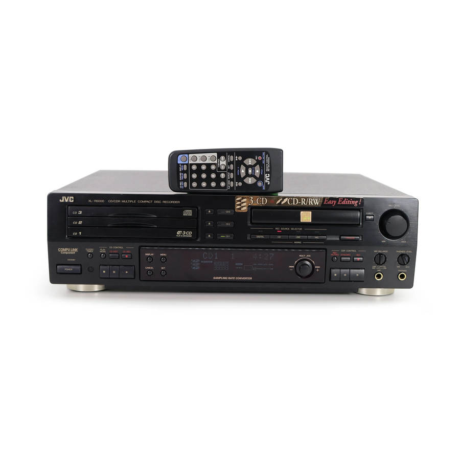
JVC XL-R5000BK Service Manual
Cd/cdr multiple compact disc recorder
Hide thumbs
Also See for XL-R5000BK:
- Instructions manual (48 pages) ,
- Instructions manual (48 pages) ,
- Service manual (9 pages)
Advertisement
www.freeservicemanuals.info
SERVICE MANUAL
CD/CDR MULTIPLE COMPACT DISC RECORDER
Contents
Safety Precautions
Important for laser products
Preventing static electricity
Disassembly method
XL-R5000BK
CD REC
SYNCHRO
DISPLAY
POWER
CD EDIT
FINALIZE
MENU
CD 1
1
2
3
XL - R5000 CD/CDR MULTIPLE COMPACT DISC RECORDER
CD 2
4
5
6
CD 3
7
8
9
CONTROL
10
+10
CD
CDR
PLAY MODE REPEAT
SET
CANCEL
CD CONTROL
CLOCK/
PLAY
TIMER
MODE
CD EDIT
CD REC
PITCH
+
STANDBY
POWER
PITCH 0
REC
PITCH
–
SHIFT
REC MUTING
REMOTE CONTROL
RM-SXLR5000J
This service manual is printed on 100% recycled paper.
COPYRIGHT
Digitized in Heiloo the Netherlands
REC SOURCE SELECTOR
3
-
CD
DIGITAL
CD
LINE
PLAY & EXCHANGE
MIC
MIXING
DISPLAY
MENU
MULTI JOG
–
CANCEL
SET
1-2
CD-R unit and 3CD changer
1-3
1-4
Description of major ICs
1-5
2000 VICTOR COMPANY OF JAPAN, LTD.
Area Suffix
U
REC LEVEL
EJECT
FINALIZE
MIN
MAX
CDR CONTROL
MIX BALANCE
PHONES LEVEL
REC
MUTING
SYNCHRO
REC
LINE
CD
MIN
MAX
+
MIC
LINE
MIC
PHONES
check mode
12/23/2018
XL-R5000BK
XL-R5000BK
Other Areas
1-19
1-22
No.20844
1-1
Not for sale!
Aug. 2000
Advertisement

Related Manuals for JVC XL-R5000BK


Summary of Contents for JVC XL-R5000BK
- Page 1 12/23/2018 XL-R5000BK XL-R5000BK SERVICE MANUAL CD/CDR MULTIPLE COMPACT DISC RECORDER XL-R5000BK Area Suffix Other Areas CD REC SYNCHRO DISPLAY POWER CD EDIT FINALIZE MENU CD 1 XL - R5000 CD/CDR MULTIPLE COMPACT DISC RECORDER REC LEVEL CD 2 EJECT...
- Page 2 12/23/2018 XL-R5000BK Safety Precautions 1. This design of this product contains special hardware and many circuits and components specially for safety purposes. For continued protection, no changes should be made to the original design unless authorized in writing by the manufacturer.
- Page 3 12/23/2018 XL-R5000BK Important for Laser Products 5.CAUTION : If safety switches malfunction, the laser is able 1.CLASS 1 LASER PRODUCT to function. 2.DANGER : Invisible laser radiation when open and inter 6.CAUTION : Use of controls, adjustments or performance of lock failed or defeated.
- Page 4 12/23/2018 XL-R5000BK Preventing static electricity Electrostatic discharge (ESD), which occurs when static electricity stored in the body, fabric, etc. is discharged, can destroy the laser diode in the traverse unit (optical pickup). Take care to prevent this when performing repairs.
- Page 5 12/23/2018 XL-R5000BK Disassembly method Top cover <Main Body> Removing the top cover (See Fig.1 and 2) Remove the four screws A on both sides of the body. Remove the two screws B on the back of the body. Fig.1...
- Page 6 12/23/2018 XL-R5000BK Removing the front panel assembly (See Fig.5 to 9) CD-R mechanism cover CD changer Prior to performing the following procedure, remove mechanism assembly CN861 the top cover. Disconnect the card wires from connector CN501, CN502, CN841, CN842 and CN861 on the main board.
- Page 7 12/23/2018 XL-R5000BK Removing the CD mechanism assembly (See Fig.10 to 13) Prior to performing the following procedure, remove the top cover and the front panel assembly. Remove the four screws F attaching the CD-R mechanism cover. Disconnect the card wires from connector CN501...
- Page 8 12/23/2018 XL-R5000BK Tie band Removing the power transformer Power transformer CN1,CN2 (See Fig.15) Prior to performing the following procedure, remove the top panel. Unsolder the terminal CN1 and CN2 on the power transformer board. Cut off the tie band and disconnect the power cord.
- Page 9 12/23/2018 XL-R5000BK <Front panel assembly> Display board Relay board Prior to performing the following procedure, remove the top cover and the front panel assembly. Removing the operation switch board / the display board (See Fig.19 and 20) Disconnect the relay board.
- Page 10 12/23/2018 XL-R5000BK Removing the microphone & headphone Front panel assembly amplifier board (See Fig.22 to 24) Remove the screw Q attaching the microphone & headphone amplifier board. Release the bracket tabs c from the bottom of the front panel.
- Page 11 12/23/2018 XL-R5000BK CD Changer Mechanism Type:VC3 Section Removing the CD Servo control board (See Fig.1) 1.Remove the metal cover. 2.Remove the CD changer mechanism assembly. 3.From bottom side the CD changer mechanism assembly, remove the two screws 1 retaining the CD servo control CN854 board.
- Page 12 12/23/2018 XL-R5000BK Stopper Check whether the lifter unit stopper has been caught into the hole at the section E of CD tray assembly as shown in Fig.5. Make sure that the driver unit elevator is positioned as shown in Fig.6 from to the second or fifth hole on the left side face of the CD changer mechanism assembly.
- Page 13 12/23/2018 XL-R5000BK Cams R1, R2 assembly Removing the CD loading mechanism assembly(See Fig.10) While turning the cams R1 and R2 assembly in the arrow direction H align the shaft I of the CD loading mechanism assembly to the position shown in Arrow Fig.10.
- Page 14 12/23/2018 XL-R5000BK Removing the cam unit (See Fig.14 to 17 ) Remove the CD loading mechanism assembly. While turning the cam gear L, align the pawl N position of the drive unit to the notch position(Fig.16) on the cam gear L.
- Page 15 12/23/2018 XL-R5000BK Removing the actuator motor and belt Gear bracket (See Fig.18 21) Remove the two screws 10 retaining the gear bracket (See Fig.18). While pressing the pawl P fixing the gear bracket in the arrow direction, remove the gear bracket Pulley gear (See Fig.18).
- Page 16 12/23/2018 XL-R5000BK Removing the cams R1/R2 assembly Slit washer and cam gear L(See Fig.22) Cam R2 Slit washer Remove the slit washer fixing the cams R1 and R2 assembly. Cam gear L By removing the two pawls S fixing the cam R1, separate R2 from R1.
- Page 17 12/23/2018 XL-R5000BK CDR Unit Tray Replacement Procedure Refer to the separate figure. When removing the tray: 1. Make sure that the pickup is located in the innermost position (usual position). If the pickup is out of the innermost position, locate it in the innermost position with care not to touch the lens.
- Page 18 12/23/2018 XL-R5000BK CRD-Unit Belt Replacement Procedure Refer to the figure below. 1. Remove the tray following to the tray removal procedure. 2. Remove the belt with the tweezers or the like. 3. Wipe over the belt creep ( in the figure) of the pulley gear (...
- Page 19 12/23/2018 XL-R5000BK CD-R unit and 3CD changer check mode How to check for 3CD and CD-R 1. Special tools and CDR & CDRW Disc. CD TEST DISC:CTS-1000 CD-R for Audio CD-RW for Audio Note: 1. Be sure to use general audio CD-R and CD-RW disks available on the market for this set.
- Page 20 When this menu item is executed, the RID code is read out and it is shown by the FL tube for 5 seconds. This selection is automatically cleared after the 5-second display. Example of display: JVCCA01089231 Manufacturer code: JVC Type code: CA01 Unique No.: 089231 2.
- Page 21 12/23/2018 XL-R5000BK Check mode Method 1. Check Mode The Check Mode is prepared for checking timer operation and display with the FL tube. 2. Check mode setup method Setup: In the status that the set is turned off, press the POWER key together with the DISPLAY key to turn on the set.
- Page 22 12/23/2018 XL-R5000BK Description of major ICs UPD784214AGF501-620(IC501):Micon 1.Pin layout 80 ~ 51 1 ~ 30 2. Pin function Symbol Description Symbol Description Non connect AVDD Power supply TEST- Connect to GND upon normal use. AVREF0 Power supply Non connect...
- Page 23 12/23/2018 XL-R5000BK AK4393VF-X (IC361): DAC 1. Pin layout 2. Block diagram 1-23 Digitized in Heiloo the Netherlands Not for sale!
- Page 24 12/23/2018 XL-R5000BK 3. Pin function Pin No. Simbol Function 1-24 Digitized in Heiloo the Netherlands Not for sale!
- Page 25 12/23/2018 XL-R5000BK M66004SP(IC721): FL driver 1. Pin layout 2. Block diagram Vcc1 Vcc2 Display code CGROM register (35bit 160) (8bit 16) FLCS Cereal reception FLCK circuit CGRAM FLDATA (35bit 16) RAM write Output port (2bit) Display SRST control code select...
- Page 26 12/23/2018 XL-R5000BK 3. Pin function Symbol Pin.No. Function FL grid control signal output. 12G~1G 1~12 FL Driver chip select. SRST Chip select signal input. FLCS Shift clock signal input. FLCK Serial data input. FLDATA Indicator control signal output. Indicator control signal output.
- Page 27 12/23/2018 XL-R5000BK MN35510(IC651): Digital servo & digital signal processer 1. Pin layout 20 ~ 41 ~ 2.Block diagram LRCKIN(MSEL) AVSS1 8TIMES BCLK(SSEL) AVDD1 DIGITAL OVER SAMPUNC SRDATAIN OUTR DEEMPHSIS DIGITAL FILTER 1BIT (PSEL) LOGIC IOSEL CLVS BLKCK OUTL CLDCK...
- Page 28 12/23/2018 XL-R5000BK 3. Pin function symbol I/O Description symbol I/O Description BCLK Not used Tracking error shunt signal output(H:shunt) LRCK Not used PLAY Not used SRDATA WVEL Not used Not used DVDD1 Power supply (Digital) RF signal input DVSS1...
- Page 29 12/23/2018 XL-R5000BK BA6897FP(IC801):4channel driver D.BUF CH1-OUTA D.BUF CH1-OUTB CH4-OUTA D.BUF CH1-INA Level CH4-OUTB Level shift shift D.BUF CH1-INB CH4-INA T.S.D TEST1 CH4-INB TEST2 BIAS IN MUTE DRIVER CH3-INB CH2-INB MUTE CH2-INA CH3-INA Level Level D.BUF D.BUF shift shift CH2-OUTB...
- Page 30 12/23/2018 XL-R5000BK TA8409S (IC851.IC852.IC853) : Motor Driver 1.Block diagram Vref Standby circuit OUT1 OUT2 Heat interception 2.Pin function INPUT OUTPUT MODE OUT1 OUT2 MOTOR STOP CW/CCW CCW/CW BRAKE TC74HC00AP (IC501) : Digital out sel 2. Function . Block diagram...
- Page 31 12/23/2018 XL-R5000BK Internal connections for FL display tube QLF0075-001 (IC721) : Display 1. Grid assignment 2. Pin connection 1-31 Digitized in Heiloo the Netherlands Not for sale!
- Page 32 12/23/2018 XL-R5000BK 3. Anode connection 1-32 Digitized in Heiloo the Netherlands Not for sale!
- Page 33 12/23/2018 XL-R5000BK XL-R5000BK VICTOR COMPANY OF JAPAN, LIMITED AUDIO & COMMUNICATION BUSINESS DIVISION PERSONAL & MOBILE NETWORK B.U 10-1,1Chome,Ohwatari-machi,Maebashi-city,371-8543,Japan Printed in Japan 1-33 No.20844 200008(O) Digitized in Heiloo the Netherlands Not for sale!
-
Page 34: Table Of Contents
12/23/2018 XL-R5000BK PARTS LIST [ XL-R5000BK] * All printed circuit boards and its assemblies are not available as service parts. Area suffix U --------------------- Other Areas - Contents - Exploded view of general assembly and parts list 3- 3... - Page 35 12/23/2018 XL-R5000BK <<MEMO>> Digitized in Heiloo the Netherlands Not for sale!
-
Page 36: Exploded View Of General Assembly And Parts List
12/23/2018 XL-R5000BK Exploded view of general assembly and parts list Block No. V.Select board 88 86 Main board Front board Front board Front board Digitized in Heiloo the Netherlands Not for sale! - Page 37 12/23/2018 XL-R5000BK XL-R5000BK Parts list (General assembly) Parts list (General assembly) Block No. M1MM Block No. M1MM Item Parts number Parts name Q'ty Description Area Item Parts number Parts name Q'ty Description Area LV10359-004A FRONT PANEL LV20726-001A FITTING(CDR) VJD5429-001SS...
-
Page 38: Cd Changer Mechanism Assembly And Parts List
12/23/2018 XL-R5000BK CD changer mechanism assembly and parts list Block No. RC3-1 Digitized in Heiloo the Netherlands Not for sale! - Page 39 12/23/2018 XL-R5000BK Parts list (CD changer mechanism) Block No. M2MM Item Parts number Parts name Q'ty Description Area VKS1144-003 CHASSIS VKS3698-003 TRAY GUIDE VKS5532-003 PULLEY GEAR VKB3000-164 BELT VKS5505-003 GEAR B VKS5506-002 GEAR C VKS5507-002 CROSS GEAR U VKS5508-002...
- Page 40 12/23/2018 XL-R5000BK Parts list (CD changer mechansm) Block No. M2MM Item Parts number Parts name Q'ty Description Area VKS2250-003 TOP BRACKET VKS5515-002 S.TRAY STOPPER VKW5156-004 TORSION SPRING QYSBSF2608Z T.SCREW QYSBSF2608Z T.SCREW --------------- CD MECHA LV40761-003A INSULATOR LV40866-002A INSULATOR VKS3703-00G...
-
Page 41: Cd Mechanism Assembly And Parts List
12/23/2018 XL-R5000BK CD mechanism assembly and parts list Block No. Grease Point FG-87HS (Grease to apply have to be a little for the exchange.) FG-87HS FG-87HS FG-87HS EXL-M7TMB EXL-M7MB Parts list ( CD mechanism ) Block No. M3MM Description... - Page 42 12/23/2018 XL-R5000BK Electrical parts list (Main board) Block No. 01 Item Parts number Parts name Remarks Area Item Parts number Parts name Remarks Area C 111 QTE1V06-106Z E CAPACITOR C 913 QCF11HZ-103 C CAPACITOR .010MF +80:-20% C 112 QCBB1HK-101Y...
- Page 43 12/23/2018 XL-R5000BK Electrical parts list Block No. 01 (Main board) Item Parts number Parts name Remarks Area Item Parts number Parts name Remarks Area D 911 1SR35-400A-T5 DIODE I/M Q 902 KTC3199/GL/-T TRANSISTOR D 912 1SR35-400A-T5 DIODE I/M Q 903...
- Page 44 12/23/2018 XL-R5000BK Electrical parts list Block No. 01 (Main board) Item Parts number Parts name Remarks Area Item Parts number Parts name Remarks Area R 502 QRE141J-104Y C RESISTOR 100K 5% 1/4W R 804 QRE141J-221Y C RESISTOR 220 5% 1/4W...
- Page 45 12/23/2018 XL-R5000BK Electrical parts list (Display board) Block No. 02 Item Parts number Parts name Remarks Area Item Parts number Parts name Remarks Area C 701 QDYB1CM-103Y C CAPACITOR JS721 QSW0446-001 R ENCODER C 702 QER41AM-107 E CAPACITOR 100MF 20% 10V...
- Page 46 12/23/2018 XL-R5000BK Block No. 02 Electrical parts list (Display board) Item Parts number Parts name Remarks Area R1402 QRE141J-223Y C RESISTOR 22K 5% 1/4W R1403 QRE141J-103Y C RESISTOR 10K 5% 1/4W R1404 QRE141J-823Y C RESISTOR 82K 5% 1/4W R2201...
- Page 47 12/23/2018 XL-R5000BK Electrical parts list (V.select board) Block No. 03 Item Parts number Parts name Remarks Area C 930 QDYB1CM-103Y C CAPACITOR C 931 QDYB1CM-103Y C CAPACITOR CN 1 QNZ0079-001Z TAB I.M CN 2 QNZ0079-001Z TAB I.M CN903 QGZ2503K1-04...
- Page 48 12/23/2018 XL-R5000BK Block No. 04 Electrical parts list (CD servo board) Item Parts number Parts name Remarks Area Item Remarks Parts number Parts name Area C 251 NCS21HJ-100X C CAPACITOR C 815 QEQF1HM-105Z NP E CAPACITOR 1.0MF 20% 50V...
- Page 49 12/23/2018 XL-R5000BK Electrical parts list Block No. 04 (CD servo board) Item Parts number Parts name Remarks Area Item Parts number Parts name Remarks Area R 612 NRSA02J-473X MG RESISTOR R 709 NRSA02J-101X MG RESISTOR R 613 NRSA02J-752X MG RESISTOR...
-
Page 50: Electrical Parts List
12/23/2018 XL-R5000BK Electrical parts list Block No. 05 (CD select switch board) Item Parts number Parts name Remarks Area CN804 QGB2016J1-07 CONNECTOR SW 1 QSW0859-001 DETECT SWITCH SW 2 QSW0859-001 DETECT SWITCH SW 3 QSW0859-001 DETECT SWITCH SW 4... -
Page 51: Packing Materials And Accessories Parts List
12/23/2018 XL-R5000BK Packing materials and accessories parts list Block No. Block No. 3-18 Digitized in Heiloo the Netherlands Not for sale! -
Page 52: Parts List
12/23/2018 XL-R5000BK Parts list (Packing) Block No. M4MM Item Parts number Parts name Q'ty Description Area LV20728-004A CARTON LV20025-003A CUSHION(F) LV20025-002A CUSHION(R) QPC06506515P POLY BAG FOR SET QPC02503510P POLY BAG FOR INST QPA01502505 ENVELOPE WIRE BATTERY PL Parts list (Accessories) Block No. - Page 53 12/23/2018 XL-R5000BK Block diagram Digitized in Heiloo the Netherlands Not for sale!
- Page 54 12/23/2018 XL-R5000BK XL-R5000BK Standard schematic diagrams System contorol circuit J541 QNS0073-001 QNS0073-001 R364 R364 S531 S531 QSW0871-001 QSW0871-001 R1501 R1501 R1508 R1508 R1502 R1502 1.5K 1.5K C1502 C1502 R1503 R1503 R549 R549 0.0015 0.0015 DAMCLK DAMCLK R367 R367 Q541...
- Page 55 12/23/2018 XL-R5000BK Regulator & optical in/out circuit CN861 CN861 QGF1205C1-04 QGF1205C1-04 J352 J352 J351 J351 GP1F32R GP1F32R GP1F32T GP1F32T C351 C351 C182 C182 R182 R182 C352 C352 22/25 22/25 R183 R183 R184 R184 IC881 IC881 2.2K 2.2K 100/10 100/10...
- Page 56 12/23/2018 XL-R5000BK XL-R5000BK Display circuit S701 S701 QSW0683-001Z QSW0683-001Z S702 S702 QSW0683-001Z QSW0683-001Z VR642 VR642 QVQ0296-A14 QVQ0296-A14 S703 S703 QSW0683-001Z QSW0683-001Z S760 S760 S751 S751 S704 S704 QSW0683-001Z QSW0683-001Z QSW0683-001Z QSW0683-001Z QSW0683-001Z QSW0683-001Z S710 S710 S761 S761 S752 S752...
- Page 57 12/23/2018 XL-R5000BK CD servo circuit Digitized in Heiloo the Netherlands Not for sale!
- Page 58 12/23/2018 XL-R5000BK XL-R5000BK Printed circuit boards Main board Digitized in Heiloo the Netherlands Not for sale!
- Page 59 12/23/2018 XL-R5000BK Display board Digitized in Heiloo the Netherlands Not for sale!
- Page 60 12/23/2018 XL-R5000BK XL-R5000BK CD servo control board Digitized in Heiloo the Netherlands Not for sale!
Need help?
Do you have a question about the XL-R5000BK and is the answer not in the manual?
Questions and answers