Table of Contents
Advertisement
Quick Links
Advertisement
Table of Contents

Related Manuals for Raidon iR2880-8S-U5


Summary of Contents for Raidon iR2880-8S-U5
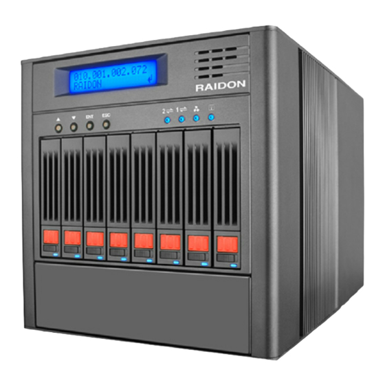
- Page 1 GR/iR2880-8S-U5 User Manual v.1.1 (November, 2010)
-
Page 2: About This Manual
Please visit our web site at www.raidon.com.tw or contact with local sales representatives for latest information. If you have any question with products of the RAIDON Technology Inc. or you need the latest product information, user’s manual and firmware please contact us at supporting@raidon.com.tw. We’ll reply you as soon and fast as possible. -
Page 3: Table Of Contents
Disk array (RAID)................5 Functions of disk array..............5 Terminology..................5 Chapter 2 Installation ................... 7 Pre-cautions................... 7 2.1.1 Features of the RAIDON SAS series products....... 7 2.1.2 Confirmation of related items............7 2.1.3 Inside the box................. 8 Installation..................8 2.2.1 Hardware.................. - Page 4 3.5.2 Physical disk................... 27 3.5.3 RAID group..................29 3.5.4 Virtual disk..................31 3.5.5 Snapshot..................35 3.5.6 Logical unit..................37 Enclosure management..............37 3.6.1 SES configuration................37 3.6.2 Hardware monitor................38 3.6.3 S.M.A.R.T..................38 3.6.4 UPS....................38 System maintenance..............39 3.7.1 System information.................
-
Page 5: Chapter 1 Introduction To Disk Array (Raid)
Chapter 1 Introduction to disk array (RAID) 1.1 Disk array (RAID) Individual hard disk, either SCSI or IDE type, is subject to the matching problems between revolution speed of driving motor and transmission interface. Transmission speed of an Ultra 160 SCSI or ATA100 IDE hard disk may have a limit of 30MB/Sec at the bandwidth of 100MHz. - Page 6 Write-Back Read-Only Dedicated Spare disks Global Spare disks Dedicated Cache Global Cache DeGrade mode S.M.A.R.T. Self-Monitoring Analysis and Reporting Technology. World Wide Name Host Bus Adapter MPIO Multi-Path Input/Output Introduction to disk array (RAID)
-
Page 7: Chapter 2 Installation
The RAIDON SAS series products may provide non-stop services with high fault tolerance when installed properly. The RAIDON SAS series products connect to related system via the SAS interface and can be configured at any RAID level for reliable data protection. At RAID 6 level there can be 2 failed disks without damaging existing data. -
Page 8: Inside The Box
2.1.3 Inside the box Items contained in the shipping carton are listed below: Item iR2880-8S-U5 GR2880-8S-U5 Main body • • External RS232 cable • • Internal RS232 cable • ▬ ▬ • MiniSAS cable (MiniSAS to MiniSAS) AC Power cable ▬... -
Page 9: Led Indications
2.2.2 LED indications Status Host Access-1/2 Fan Failure Controller Status Power on (booting) ▬ Red / Lights On Blue / Lights On Red / Lights On RAID building Blue / Lights On ▬ Blue / Lights On Blue / Blinks Red / Lights On Fan Failure Blue / Lights On... -
Page 10: Hardware Installation
Please install your RAIDON SAS series product by following steps listed below: Note : The following steps are for the iR2880-8S-U5 model. For GR2880-8S-U5 model please skip Step 5. Step 1 Open the shipping carton, remove the main body of your product out of the carton and place it on a working bench. -
Page 11: Log Into The Administration Interface
Step 7 The installation is completed. You may power on your computer system for setup and application. 2.3 Log into the administration interface You may login and manage your RAIDON SAS series products by following three steps described below: Installation... -
Page 12: Web Gui
The RAIDON SAS series products support GUI for system management. Make sure that related LAN port is connected in advance. For network environment with a DHCP server your RAIDON SAS series products can get IP address automatically. You may get the IP address through LCM of the equipment. See Chapter 3 for required settings. -
Page 13: Rs232 (Super Terminal)
(192.168.0.xxx) of your 2880 series product (Please contact your system administrator for confirmation.) Step 5 Click OK after you have filled in required values. (The IP address of your RAIDON SAS series product must remain in the same segment after any IP address change for successful system operation.) - Page 14 Step 3 Select COM port. (The COM port being connected.) Step 4 Type in required settings. Bits per second: 115200 Data bits: 8 Parity: None Stop bits: 1 Flow control: None Step 5 Select terminal type by clicking at File → Properties → Setup. Select type “VT100”. Select OK to finish setup operation.
-
Page 15: Secure Shell
(The default account/password is: admin / 1234.) 2.3.3 Secure Shell Your RAIDON SAS series product may be connected by way of Secure Shell (SSH) for better data transmission security. The SSH client software can be downloaded at the following web sites: SSH Win Client WWW: http://www.ssh.com/... -
Page 16: Embedded Controlse
ESC (exit) and ENT (select). A screen as shown below displays after the system is turned on: XXX . XXX . XXX . XXX RAIDON GR2880U5 Press the ENT (select) key then press the ▲ (up) and ▼(down) keys to select the LCM functions. - Page 17 [Apply The [new x disk]▲ ▼ Adjust RAID 3 Config] xxx BG Volume Size [▲Yes No▼] RAID 5 RAID 6 RAIDON RAID 0+1 GR/iR2880U5 [IP Config] ▲ ▼ [Static IP] [IP Address] [192.168.010.050] [View IP Setting] [IP Subnet Mask] [255.255.255.0] [IP Gateway] [192.168.010.254]...
-
Page 18: System Buzzer
3. The alarm sound turns off automatically when the system failure or error is solved. 2.4.3 LED Your RAIDON SAS series product is featured with LED indicators for system status. You may check system status by viewing indicator lights. Installation... -
Page 19: Chapter 3 Introduction To The Gui
Chapter 3 Introduction to the GUI 3.1 Structure of the GUI The GUI is described below: Quick Install Step 1 / Step 2 / Confirm → System Configuration System setting System name / Date and time / System indication ... -
Page 20: Login
Please refer to Chapter 2 for required setup. Illustration below shows you how to log in the iR2880-8S-U5 model with default IP address. (The operation screens for the GR2880-8S-U5 model are the same as that of the iR2880- 8S-U5 one except the model number shown at the upper left corner.) Open up your browser and type... -
Page 21: Quick Installation
2. Select the least number of disk drives based on the RAID level or volume size. The Quick installation function is exemplified below with the iR2880-8S-U5 model: Step 1: Select RAID level after the Quick installation function is selected. Please refer to the figure below. -
Page 22: System Configuration
Step 2: Confirm the selected RAID level and capacity by clicking at the Confirm button if the selections are correct. The setup process is completed after confirmation. Figure 3.3.2 Step 3: The screen of Virtual disk options displays afterwards and the preliminary hardware setup is now completed. -
Page 23: System Setting
The System indication function assists you to find the desired equipment location by the LED indicator of itself when there are multiple RAIDON SAS series products installed in your system. The LED indicator lights (LED of Controller Status) can be found at the far right of the front of your product. -
Page 24: Login Setting
Figure 3.4.2.1 3.4.3 Login setting The Login setting option lets you set up system login related options including automatic logout time, login restrictions and login password. 1. Auto logout: available options are Disable, 5 min, 30 min and 1 hour. The user of the system is logged out by the system when no action has been taken by the user in given time span such that other users may log in the system. -
Page 25: Mail Setting
3.4.4 Mail setting You may specify up to 3 email accounts for receiving notices of system events by selecting the Mail option. Some email servers may filter “Mail-from address” to block spam mails. Please fill in related data in the required fields and click the “Send test mail” option to validate email usage. You may need to get help from your system administrator for proper settings of related system setup. -
Page 26: Disk Drive Configuration
Figure 3.4.5.2 You may send the related log files to a log server if you have installed one. Required setup values can be provided in the System log server screen. Figure 3.4.5.3 You may select to display desired information with the Event log filter function. Figure 3.4.5.4 You may turn on and off the beeper of your system with the Buzzer function. -
Page 27: Physical Disk
Figure 3.5.1.1 Step 2: Select to accept one of the pre-defined disk drive combinations or to configure a new one by yourself. Figure 3.5.1.2 Step 3: Setup capacity of disk volume. (The default size is the whole available space.) Figure 3.5.1.3 Step 4: Confirm settings given by you. - Page 28 For hard disk being set up as a RAID drive the text “RAID disk” may show up in the Usage field or the “Free disk” message is display instead. See Figure3.5.2.1 for illustration. You may click buttons below the slot numbers to give instructions to individual hard disk. The Status and Usage fields display related information afterwards (see Figure3.5.2.2).
-
Page 29: Raid Group
Field descriptions for physical hard disks: The hard disk ID. Click the blue button below individual number to display Slot details about given disks. Size Change the unit of disk volume to GB or MB. Name of the RAID Group. Current hard disk status. - Page 30 Figure 3.5.3.1 Click Confirm and settings of the newly created RAID group displays. Figure 3.5.3.2 You may set up additional Migrate, Move, Active, Deactivate, Parity check, Delete, Set disk property and More information options for the newly set up RAID group. Figure 3.5.3.3 Select the Migrate function to expand the existing RAID group or change the RAID level settings.
-
Page 31: Virtual Disk
Figure 3.5.3.6 The Set disk property function can be used to change settings of given RAID group including: Write cache, Standby, Readahead and Command queuing. Figure 3.5.3.7 The More information option displays detailed information of given RAID group. Figure 3.5.3.8 3.5.4 Virtual disk You may view status of each virtual disk with the Virtual disk function. - Page 32 WT = Write-through cache Write WB = Write-back cache RO = Read-only Priority High / Middle / Low priorities between virtual disks. 0~4, with default at 4. The bigger the number the higher performance ratio for Bg rate its background jobs (like Rebuilding). Status of virtual disk.
- Page 33 Click the button below each number to do detailed setup as described below. Figure 3.5.4.2 1. Extend This option lets you expand capacities with space not used by RG. 2. Parity check This option lets you do parity check against selected disk. This option is available to redundant RAID level 3, 5, 6, 30, 50 and 60 only.
- Page 34 7. Set clone Set dedicated VD for backup, please select the type as “Backup” when creating VD, so that the VD can be designated for Clone, and it only workable when the volume size of VD is equal to or bigger than the VD which it will backup from.
-
Page 35: Snapshot
Snapshot space: there are six options from selection of 0.5, 1, 1.5, 2, 2.5 and 3 (default is at 2), these numbers representing the multiple ratios for the VD., For example, when multiple ratio is at "2" and VD is 100GB, system will create a volume of 200GB for Snapshot space. Threshold: there are three options in percentage from Snapshot space usage of 40%, 50% and 60%. - Page 36 3. Take snapshot Create new Snapshot immediately. Note : Snapshot function is not as creating identical data for backup, it is based on existing database recovering to different Snapshot stages, if the database is damaged or formatted, it may not be workable for system recovery.
-
Page 37: Logical Unit
5. Detach (appear only after being exposed) Remove LUN for given Snapshot. 6. List LUN (appear only after being exposed) Display list of all the connected LUN. 3.5.6 Logical unit Entering the Logical unit function to view/add logical units attached to each virtual hard disk. Figure 3.5.6.1 Click the button below Host ID to delete given LUN. -
Page 38: Hardware Monitor
3.6.2 Hardware monitor Select the Hardware monitor function to view current voltage and temperature. Figure 3.6.2.1 Please check the Auto shutdown option to shut down your system when the voltage and temperature are over the normal operational range for better data protection. 3.6.3 S.M.A.R.T. -
Page 39: System Maintenance
The system now supports the smart-UPS function provided by the American Power Conversion Corp. (APC) UPS of other suppliers are acceptable but without the related setup function. Select types of UPS. For APC UPS please select Smart-UPS or None for UPS Type any other one. -
Page 40: Upgrade
Upgrading firmware carelessly may void settings of the whole system or even lead to data loss. Under no circumstances will RAIDON Technology Inc. be liable in any way for this kind of damage. Should you have any firmware upgrade requirements please contact supporting@raidon.com.tw... -
Page 41: Import And Export
3.7.5 Import and export Select the Import and export option to import and export setup related values. Figure 3.7.5.1 3.7.6 Event log Select the Event log option to view the log of events starting from system creation to this moment. You may select “Download”...
Need help?
Do you have a question about the iR2880-8S-U5 and is the answer not in the manual?
Questions and answers