Ferroli ATLAS D 37 K 130 UNIT Instructions For Use, Installation And Maintenance
Hide thumbs
Also See for ATLAS D 37 K 130 UNIT:
- Instructions for use, installation & maintenance (80 pages) ,
- Instructions for use manual (84 pages)
Advertisement
Available languages
Available languages
Quick Links
ATLAS D 37 K 130 UNIT
IT - ISTRUZIONE PER L'USO L'INSTALLAZIONE E LA MANUTENZIONE
ES - INSTRUCCIONES DE USO, INSTALACIÓN Y MANTENIMIENTO
TR - KULLANMA, KURULUM VE BAK M TALIMATLAR
EN - INSTRUCTIONS FOR USE, INSTALLATION AND MAINTENANCE
FR - INSTRUCTIONS D'UTILISATION, D'INSTALLATION ET D'ENTRETIEN
GR -
,
NL - AANWIJZINGEN VOOR GEBRUIK, INSTALLATIE EN ONDERHOUD
RU -
,
Advertisement

Related Manuals for Ferroli ATLAS D 37 K 130 UNIT


Summary of Contents for Ferroli ATLAS D 37 K 130 UNIT
- Page 1 ATLAS D 37 K 130 UNIT IT - ISTRUZIONE PER L’USO L'INSTALLAZIONE E LA MANUTENZIONE ES - INSTRUCCIONES DE USO, INSTALACIÓN Y MANTENIMIENTO TR - KULLANMA, KURULUM VE BAK M TALIMATLAR EN - INSTRUCTIONS FOR USE, INSTALLATION AND MAINTENANCE FR - INSTRUCTIONS D'UTILISATION, D'INSTALLATION ET D'ENTRETIEN...
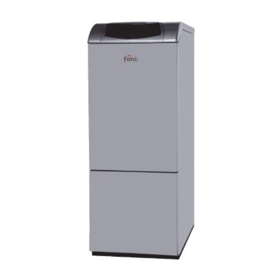
- Page 2 ATLAS D 37 K 130 UNIT è un generatore di calore ad alto rendimento, per la produzione di acqua calda sanitaria e per il riscaldamento, funzionante con un bruciatore a gasolio. Il corpo caldaia è costituito da elementi in ghisa, assemblati con biconi e tiranti in acciaio sovrapposti ad un bollitore per l’acqua calda sanitaria ad accumulo rapido, vetrificato, e...
- Page 3 ATLAS D 37 K 130 UNIT Accensione caldaia Regolazione temperatura sanitario • Aprire le valvole di intercettazione combustibile. Agire sui tasti sanitario +/- (part. 1 e 2 - fig. 1) per variare la temperatura da un minimo • Fornire alimentazione elettrica all'apparecchio.
- Page 4 ATLAS D 37 K 130 UNIT Se la temperatura ambiente risulta inferiore al valore desiderato si consiglia di impostare Kit vaso e rubinetto opzionale una curva di ordine superiore e viceversa. Procedere con incrementi o diminuzioni di una È disponibile a richiesta un kit opzionale composto da un vaso di espansione sanitario e unità...
- Page 5 Circolatore Bollitore ad alta efficienza 3.4 Collegamento bruciatore Per un corretto funzionamento della caldaia ATLAS D 37 K 130 UNIT, il selettore di ve- Il bruciatore è dotato di tubi flessibili e filtro per il collegamento alla linea di alimentazione locità...
- Page 6 (in possesso dei requisiti tecnici professionali previsti dalla normativa vigente) come il personale del Servizio Tecnico Assistenza Clienti di Zona. FERROLI declina ogni responsabilità per danni a cose e/o persone derivanti dalla ma- nomissione dell’apparecchio da parte di persone non qualificate e non autorizzate.
- Page 7 ATLAS D 37 K 130 UNIT Regolazione pressione pompa Testa e serranda aria La pressione della pompa viene tarata in fabbrica per un funzionamento ottimale e di Regolare la testa e la portata aria in funzione della potenza del bruciatore come indicato norma non dovrebbe essere modificata.
- Page 8 ATLAS D 37 K 130 UNIT 4.2 Messa in servizio Tempo di preaccensione Tempo di postaccensione Verifiche da eseguire alla prima accensione, e dopo tutte le operazioni di ma- Tempo di preriscaldamento nutenzione che abbiano comportato la disconnessione dagli impianti o un inter-...
- Page 9 ATLAS D 37 K 130 UNIT Pulizia della caldaia Codice Anomalia Possibile causa Soluzione anomalia Togliere l’alimentazione elettrica alla caldaia. Anomalia preriscaldatore Togliere il bruciatore (vedi paragrafo precedente). (non chiude il contatto in Cablaggio interrotto Verificare il cablaggio Togliere il pannello superiore.
- Page 10 ATLAS D 37 K 130 UNIT 5. CARATTERISTICHE E DATI TECNICI Legenda figure cap. 5 Valvola di sicurezza e antiritorno Uscita fumi Mandata impianto - Ø 3/4” Ritorno impianto - Ø 1” Valvola di sicurezza riscaldamento Circolatore riscaldamento Sfiato aria automatico...
- Page 11 ATLAS D 37 K 130 UNIT 5.2 Circuito idraulico - Prevalenza del circolatore con impostazione a “prevalenza proporzionale”. H [m H Q [m fig. 42 Perdite di carico caldaia fig. 40 - Circuito idraulico 5.4 Tabella dati tecnici 5.3 Diagrammi...
- Page 12 ATLAS D 37 K 130 UNIT cod. 3541I110 - Rev. 02 - 10/2016...
- Page 13 ATLAS D 37 K 130 UNIT 5.5 Schema elettrico 230V 50Hz T° T° DBM06E DSP05 fig. 43 - Schema elettrico Circolatore riscaldamento Sonda temperatura sanitario Termostato ambiente (opzionale) Circolatore bollitore Sonda esterna (opzionale) Cronocomando Remoto (opzionale) Trasduttore di pressione Sensore doppio (Sicurezza + riscaldamento) Trasformatore d’accensione...
- Page 14 Entro 30 giorni dalla messa in servizio il Cliente deve richiedere ad un Centro di Assistenza Autorizzato da Ferroli S.p.A. l’intervento gratuito per la verifi ca iniziale del prodo o e l’a vazione, tramite registrazione, della garanzia convenzionale. Trascorsi oltre 30 giorni dalla messa in servizio la presente Garanzia Convenzionale non sarà...
- Page 15 , el uso y el mantenimiento. ATLAS D 37 K 130 UNIT es un generador de calor de alto rendimiento, para producción de agua caliente sanitaria y calefacción , equipado con quemador de gasóleo. El cuerpo comfort de la caldera está...
- Page 16 ATLAS D 37 K 130 UNIT Encendido de la caldera Regulación de la temperatura del agua sanitaria • Abrir las válvulas de interceptación combustible. Mediante las teclas +/- (1 y 2 - fig. 1) se puede regular la temperatura del agua sanitaria •...
- Page 17 ATLAS D 37 K 130 UNIT Kit vaso y grifo opcional Si la temperatura ambiente es inferior al valor deseado , se aconseja seleccionar una curva de orden superior, y viceversa. Probar con aumentos o disminuciones de una uni- Se ofrece un kit opcional formado por un vaso de expansión para agua sanitaria y un dad y controlar el resultado en el ambiente.
- Page 18 Circulador del acumulador de alta eficiencia 3.4 Conexión del quemador Para que la caldera ATLAS D 37 K 130 UNIT funcione correctamente, el selector de ve- El quemador está provisto de tubos flexibles y de filtro para la conexión a la línea de ali- locidad (fig.
- Page 19 Servicio de Asistencia local. FERROLI declina toda responsabilidad por daños materiales o personales derivados de la manipulación del aparato por personas que no estén debidamente autorizadas.
- Page 20 ATLAS D 37 K 130 UNIT Regulación de la presión de la bomba Cabezal y compuerta de aire La presión de la bomba se regula en fábrica para un funcionamiento optimizado, y nor- Regular el cabezal y el caudal del aire en función de la potencia del quemador, tal como malmente no debería modificarse.
- Page 21 ATLAS D 37 K 130 UNIT 4.2 Puesta en servicio Tiempo de preencendido Tiempo de postencendido Controles que se han de efectuar durante el primer encendido, tras las opera- Tiempo de precalentamiento ciones de mantenimiento que exijan desconectar la caldera y después de cual- Señales de salida del aparato...
- Page 22 ATLAS D 37 K 130 UNIT Limpieza de la caldera Código Anomalía Causa posible Solución anomalía Desconecte la alimentación eléctrica de la caldera. Anomalía del precalenta- Quite el quemador (vea el apartado anterior). dor (no cierra el contacto Cableado interrumpido Controlar el cableado Retire el panel superior.
- Page 23 ATLAS D 37 K 130 UNIT 5. CARACTERÍSTICAS Y DATOS TÉCNICOS Leyenda de las figuras cap. 5 Válvula de seguridad y retención Salida de humos Ida a calefacción - Ø 3/4" Retorno de calefacción - Ø 1" Válvula de seguridad calefacción Circulador de calefacción...
- Page 24 ATLAS D 37 K 130 UNIT 5.2 Circuito hidráulico - Altura de elevación del circulador con presión de impulsión proporcional H [m H Q [m fig. 42 Pérdidas de cargas de la caldera fig. 40 - Circuito hidráulico 5.4 Tabla de datos técnicos 5.3 Diagramas...
- Page 25 ATLAS D 37 K 130 UNIT cod. 3541I110 - Rev. 02 - 10/2016...
- Page 26 ATLAS D 37 K 130 UNIT 5.5 Esquema eléctrico 230V 50Hz T° T° DBM06E DSP05 fig. 43 - Esquema eléctrico Circulador de calefacción Sonda de temperatura ACS Termostato de ambiente (opcional) Circulador del acumulador Sonda exterior (opcional) Cronomando remoto (opcional) Transductor de presión...
- Page 27 Las posibles reclamaciones deberán efectuarse ante el organismo competente en esta materia. Sede Central y Fábrica: Polígono Industrial de Villayuda Apartado de Correos 267 - 09007 Burgos Tel. 947 48 32 50 Fax 947 48 56 72 e.mail: ferroli@ferroli.es Certificado de funcionamiento Llene por favor la cupón unida http//www.ferroli.es Dirección Comercial: Avda.
- Page 28 önemli bilgiler vermektedir. ATLAS D 37 K 130 UNIT s v yak tla (mazot) çal an brülörler ile donat lm , s cak su üretimi veya s tma amaçl kullan lan yüksek performansl bir s üretecidir. Kombinin gövdesi, çelik man on ve gergilerle bir araya getirilerek, h zl s cak su sa layan, vitrifiye...
- Page 29 ATLAS D 37 K 130 UNIT Kombinin yak lmas S cak musluk suyu s cakl ayar • Yak t açma-kapama valf n aç n z. S cakl minimum 10°C ile maksimum 65°C aras nda ayarlamak için s cak musluk suyu •...
- Page 30 ATLAS D 37 K 130 UNIT E er ortam s cakl istenilen de erin alt na dü erse, daha yüksek dereceden bir e ri Opsiyonel tank ve musluk kiti ayarlanmas veya tersi durumda bunun tersinin uygulanmas tavsiye edilir. Bir derece Talep üzerine, s cak su genle me tank ve muslu undan olu an opsiyonel bir kit mevcut-...
- Page 31 Yüksek verimli kazan sirkülatörü 3.4 Brülörün tak lmas ATLAS D 37 K 130 UNIT kombinin düzgün bir ekilde çal mas için, h z seçici (bkz. Brülör, s v yak t (mazot) beslemesine ba lant için esnek hortumlar ve bir filtre ile do- ek.
- Page 32 (yürürlükteki standartlar n öngördü ü profesyonel teknik gereklilikler hakk nda bilgi sahi- bi olan bir ki i) taraf ndan gerçekle tirilmelidir. FERROLI cihaz n yetkisiz ki iler taraf ndan kurcalanmas ndan kaynaklanan, insanlara ve/veya e yalara gelebilecek hasarlarla ilgili hiçbir sorumluluk kabul etmez.
- Page 33 ATLAS D 37 K 130 UNIT Pompa bas nc ayar Hava kapak ve ba l Pompan n bas nc , optimum i letim (çal ma) için fabrikada ayarlanm olup, normalde Hava kafas n /ba l n ve ç k n , belirtilmekte olan brülörün çal mas na göre ayar- de i tirilmemesi gerekmektedir.
- Page 34 ATLAS D 37 K 130 UNIT 4.2 Servise alma Ön- s tma süresi Cihaz ç k sinyalleri lk çal t rma an nda ve sistemlerden ayr lmas n gerektiren i lemlerden veya Giri te gerekli sinyaller emniyet cihazlar nda ya da kombinin di er aksamlar nda gerçekle tirilen müdahalelerden sonra yap lacak kontroller:...
- Page 35 ATLAS D 37 K 130 UNIT Kombinin temizlenmesi Ar za Ar za Olas neden Çözüm kodu Kombiye gelen elektrik beslemesini kesin. Ön- s t c ar zas (120 Brülörü ç kart n z (bir önceki paragrafa bak n z). saniye içinde konta...
- Page 36 ATLAS D 37 K 130 UNIT 5. TEKNIK ÖZELLIKLER VE VERILER ekil aç klamalar cap. 5 Emniyet ve geri dönü -önleme valf Baca gaz ç k Sistem ç k - Ø 3/4” Sistem giri i - Ø 1” Is tma emniyet valf Is tma sirkülatörü...
-
Page 37: Table Of Contents
ATLAS D 37 K 130 UNIT 5.2 Hidrolik devre - "Oransal bas nç" ayarl sirkülatör bas nc . H [m H Q [m ek. 42 Kombi yük kay plar ek. 40 - Hidrolik devre 5.4 Teknik veriler tablosu 5.3 Diyagramlar Sirkülatör yük / bas nç... - Page 38 ATLAS D 37 K 130 UNIT 5.5 Elektrik emas 230V 50Hz T° T° DBM06E DSP05 ek. 43 - Elektrik emas Is tma sirkülatörü S cak su s sensörü Ortam termostat (opsiyonel) Kazan sirkülatörü Harici sensör (opsiyonel) Uzaktan zamanlay c kumanda (opsiyonel) Bas nç...
-
Page 39: Bar
ATLAS D 37 K 130 UNIT is a high-efficiency heat generator for domestic hot water pro- duction and heating, using an oil burner. The boiler shell consists of cast-iron elements, assembled with double cones and steel stays placed over a DHW quick storage domes- tic hot water tank, vitrified, and protected against corrosion by a magnesium anode. - Page 40 ATLAS D 37 K 130 UNIT Boiler lighting DHW temperature adjustment • Open the fuel on-off valves. Use the DHW buttons +/- (details 1 and 2 - fig. 1) to adjust the temperature from a min. • Switch on the power to the unit.
- Page 41 ATLAS D 37 K 130 UNIT If the room temperature is lower than the required value, it is advisable to set a higher Optional cock and tank kit order curve and vice versa. Proceed by increasing or decreasing in steps of one and An optional kit comprising a DHW expansion tank and filling cock is available on request.
- Page 42 High efficiency hot water tank circulating pump 3.4 Burner connection For proper operation of the boiler ATLAS D 37 K 130 UNIT, the speed selector (see The burner is equipped with flexible pipes and a filter for connection to the oil feed line.
-
Page 43: Bar
Qualified Personnel (meeting the professional technical requirements of current regulations) such as the personnel of the Local After-Sales Technical Service. FERROLI declines any liability for damage and/or injury caused by unqualified and un- authorised persons tampering with the unit. 4.1 Adjustments TEST mode activation Press the heating buttons (details 3 and 4 - fig. - Page 44 ATLAS D 37 K 130 UNIT Pump pressure adjustment Head and air shutter The pump pressure is factory set for optimum operation and should not normally be Adjust the head and air flow rate according to the burner power as indicated in fig. 29 changed.
- Page 45 ATLAS D 37 K 130 UNIT 4.2 Commissioning Post-ignition time Preheating time Checks to be done at first lighting, and after all maintenance operations that in- Output signals from the unit volved disconnection from the systems or work on safety devices or parts of the...
- Page 46 ATLAS D 37 K 130 UNIT Boiler cleaning Fault Fault Possible cause Cure code Disconnect the power supply to the boiler. Preheater fault (the Remove the burner (see preceding section). contact does not close Wiring disconnected Check the wiring Remove the upper panel.
- Page 47 ATLAS D 37 K 130 UNIT 5. TECHNICAL DATA AND CHARACTERISTICS Key of figures cap. 5 Safety and non-return valve Fume outlet System delivery - Ø 3/4” System return - Ø 1” Heating safety valve Heating circulating pump Automatic air vent...
-
Page 48: Q [M 3 /H]
ATLAS D 37 K 130 UNIT 5.2 Hydraulic circuit - Circulating pump head with setting at "proportional head”. H [m H Q [m fig. 42 Boiler pressure losses fig. 40 - Hydraulic circuit 5.4 Technical data table 5.3 Diagrams Circulating pumps Head/Pressure loss... - Page 49 ATLAS D 37 K 130 UNIT cod. 3541I110 - Rev. 02 - 10/2016...
- Page 50 ATLAS D 37 K 130 UNIT 5.5 Wiring diagram 230V 50Hz T° T° DBM06E DSP05 fig. 43 - Wiring diagram Heating circulating pump DHW temperature probe Room thermostat (optional) Hot water tank circulating pump External probe (optional) Remote Timer Control (optional)
- Page 51 ATLAS D 37 K 130 UNIT est un générateur thermique de chauffage et production d'eau chaude sanitaire à haut rendement doté de brûleur à gazole. Le corps de la chaudière se compose d'éléments en fonte avec bicônes et tirants en acier, superposés à un ballon pour l'eau chaude sanitaire à...
- Page 52 ATLAS D 37 K 130 UNIT Allumage de la chaudière Réglage de la température de l'eau chaude sanitaire • Ouvrir les vannes d'arrêt du combustible. Pour régler la température entre 10 °C (minimum) et 65 °C (maximum), agir sur les tou- •...
- Page 53 ATLAS D 37 K 130 UNIT Si la température ambiante est inférieure à la valeur désirée, il est conseillé de définir Kit vase et robinet optionnel une courbe supérieure et vice versa. Augmenter ou diminuer d'une unité et vérifier le ré- Sur demande il est disponible un kit optionnel composé...
- Page 54 Circulateur Ballon haute efficacité 3.4 Raccordement du brûleur Pour assurer le fonctionnement correct de la chaudière ATLAS D 37 K 130 UNIT, mettre Le brûleur est doté de tuyaux flexibles et de filtre de branchement à la ligne d'alimenta- le sélecteur de vitesse (voir fig. 17) sur la position III.
- Page 55 à des techniciens qualifiés (ayant suivi la formation professionnelle prévue par les normes en vigueur) tel que le personnel du SAV. FERROLI Toute responsabilité contractuelle et extracontractuelle du constructeur est exclue pour les dommages causés par des erreurs dans l'installation et l'utilisation et, dans tous les cas, par le non-respect des instructions fournies par le constructeur.
- Page 56 ATLAS D 37 K 130 UNIT Réglage de la pression de la pompe Tête et registre d'air La pression de la pompe est réglée en usine pour un fonctionnement optimal. En règle Régler la tête et le débit de l'air en fonction de la puissance du brûleur comme indiqué...
- Page 57 ATLAS D 37 K 130 UNIT 4.2 Mise en service Temps de préchauffage Signaux de sortie de l'appareil Vérifications à effectuer au premier allumage et après toutes les opérations Signaux nécessaires en entrée d'entretien ayant occasionné le débranchement des installations ou une inter- vention sur des dispositifs de sécurité...
- Page 58 ATLAS D 37 K 130 UNIT Nettoyage de la chaudière Code Anomalie Causes probables Solution anomalie Couper l'alimentation électrique de la chaudière.. Anomalie paramètres Vérifier et modifier éventuellement le Démonter le brûleur (voir paragraphe précédent). Mauvais paramétrage de la carte carte paramètre carte...
- Page 59 ATLAS D 37 K 130 UNIT 5. CARACTÉRISTIQUES ET DONNÉES TECHNIQUES Légende des figures cap. 5 Clapet de sécurité et anti-retour Sortie de fumée Départ installation - Ø 3/4" Départ installation - Ø 1” Soupape de sûreté circuit chauffage Circulateur circuit chauffage...
- Page 60 ATLAS D 37 K 130 UNIT 5.2 Circuit hydraulique - Pression du circulateur avec réglage à « hauteur d'élévation proportionnelle ». H [m H Q [m fig. 42 Pertes de charge chaudière fig. 40 - Circuit hydraulique 5.4 Tableau des caractéristiques techniques 5.3 Diagrammes...
- Page 61 ATLAS D 37 K 130 UNIT cod. 3541I110 - Rev. 02 - 10/2016...
- Page 62 ATLAS D 37 K 130 UNIT 5.5 Schéma électrique 230V 50Hz T° T° DBM06E DSP05 fig. 43 - Schéma électrique Circulateur circuit chauffage Sonde température sanitaire Thermostat d'ambiance (option) Circulateur ballon Sonde extérieure (option) Chronocommande à distance (option) Transducteur de pression Capteur double (sécurité...
- Page 63 ATLAS D 37 K 130 UNIT 13 = 14 = • 15 = Eco (Economy) Comfort 16 = • 17 = 18 = • 19 = 20 = 21 = • 22 = 23 = 24 = 25 = •...
- Page 64 ATLAS D 37 K 130 UNIT • 2 - fig. 1) • 10°C 65°C . 10 . 5 - • • • on/off ( . 9 - fig. 1) . 5 - fig. 1) " . 6 - “ ”.
- Page 65 ATLAS D 37 K 130 UNIT . 1 - fig. 16) 1,0 bar. . 13 - OFFSET = 20 OFFSET = 40 . 16 - . 14 - tabella 1. . 5 - fig. 1) ý ß Ý ý ß...
- Page 66 ATLAS D 37 K 130 UNIT ATLAS D 37 K 130 UNIT, . fig. 17) III. fig. 20. . 17 . 20 - (LMAX) ý Dp-v ý ü ü ý Þ ý . 21 - åéê. 18 åéê. 19 Dp-v (fig.
- Page 67 ATLAS D 37 K 130 UNIT FERROLI 4 - fig. 1) . 24 - fig. 1) . 12 - fig. 1). . 24 - . 26 - TEST tabella 2 "Y" 3A max 12%. 2 cm . 2 - Þ...
- Page 68 ATLAS D 37 K 130 UNIT fig. 29 B (fig. 30) «6» fig. 27 fig. 28. A (fig. 30) 10 - 14 bar. A (kW) 15.0 20.0 25.0 30.0 35.0 40.0 45.0 50.0 55.0 60.0 5,06 C (kg/h) 1,26 1,69...
- Page 69 ATLAS D 37 K 130 UNIT • sez. 2.3. • • • • • • • • • • • • • • • 12%. • • • • • • • • • • • . 32 - •...
- Page 70 ATLAS D 37 K 130 UNIT ü ß Þ ß ý ß Ü Ü Ý Þ , Ü Ý ý Ý Ý Ý ß Ü Ý «A» «B». Ü Þ ß Ý ß Þ «C» «D». ý ß Þ Þ 1 Þ...
- Page 71 ATLAS D 37 K 130 UNIT cap. 5 3/4” 1” 3/4” 3/4” 3/4” . 38 - 120-130 mm . 37 - . 39 - cod. 3541I110 - Rev. 02 - 10/2016...
- Page 72 ATLAS D 37 K 130 UNIT « H [m H Q [m . 42 . 40 - ß Ü Þ « ». Ý ATLAS D 37 K 130 UNIT ü ß Ý Þ Þ Ý (Hs) 41.9 Ý Þ Þ Ý...
- Page 73 ATLAS D 37 K 130 UNIT cod. 3541I110 - Rev. 02 - 10/2016...
- Page 74 ATLAS D 37 K 130 UNIT 230V 50Hz T° T° DBM06E DSP05 . 43 - cod. 3541I110 - Rev. 02 - 10/2016...
- Page 75 (detail 12 en 13 - Wij danken u dat uw keus is gevallen op FERROLI, een ketel volgens geavanceerd con- fig. 1). Controleer of de functie Comfort geactiveerd is(detail 15 - fig. 1) cept en vooruitstrevende technologie, een uiterst betrouwbare constructie van hoog- De streepjes die de temperatuur van het sanitaire water aangeven (detail 11 - fig.
- Page 76 ATLAS D 37 K 130 UNIT Aanzetten verwarmingsketel Regeling van temperatuur sanitair water • Maak de brandstofkleppen open. +/- Bedien de toetsen voor sanitair water (detail 1 en 2 - fig. 1) om de temperatuur te va- • Schakel de stroom naar het apparaat in.
- Page 77 ATLAS D 37 K 130 UNIT Als de omgevingstemperatuur lager blijkt dan de gewenste waarde wordt aanbevolen Optionele set expansievat en kraan een hogere curve in te stellen en omgekeerd. Verhoog of verlaag de curve met één Op aanvraag is een optionele set verkrijgbaar, bestaande uit een expansievat sanitair eenheid en verifieer daarna de omgevingstemperatuur.
- Page 78 Hoog efficiënte circulatiepomp boiler 3.4 Aansluiting van de brander Voor een goede werking van de verwarmingsketel ATLAS D 37 K 130 UNIT, moet de De brander is uitgerust met slangen en een filter voor aansluiting op de olietoevoerlei- snelheidskeuzeknop (zie fig. 17) op stand III gezet worden.
- Page 79 Personeel (dat voldoet aan de technisch-professionele vereisten op grond van de geldende voorschriften), zoals het personeel van de plaatselijke Technische Klantenser- vice. FERROLI is geenszins aansprakelijk voor schade aan zaken en/of persoonlijk letsel, ve- roorzaakt door ingrepen op het apparaat, uitgevoerd door onbevoegde en ondeskundige personen.
- Page 80 ATLAS D 37 K 130 UNIT Regeling pompdruk Voor een optimale werking wordt de druk van de pomp in de fabriek afgesteld; dit dient in de regel niet te worden gewijzigd. Als het om bijzondere redenen echter nodig is een andere druk in te stellen, moet, nadat de manometer is aangebracht en de brander is ingeschakeld, de stelschroef "6", aangegeven in fig.
- Page 81 ATLAS D 37 K 130 UNIT 4.2 Inwerkingstelling Veiligheidstijd Tijd voorontsteking Controles die uitgevoerd moeten worden bij de eerste ontsteking en naar aan- Tijd na-ontsteking leiding van alle onderhoudswerkzaamheden die afsluiting van de installaties Voorverwarmingstijd met zich meebrengen, of na een ingreep op de veiligheidsinrichtingen of delen...
- Page 82 ATLAS D 37 K 130 UNIT Reiniging van de verwarmingsketel Code Storing Mogelijke oorzaak Oplossing storing Schakel de stroom naar de verwarmingsketel uit. Storing voorverwarmer Verwijder de brander (zie de vorige paragraaf). (het contact wordt niet Breuk in bedrading Controleer de bedrading Verwijder het bovenste paneel.
- Page 83 ATLAS D 37 K 130 UNIT 5. KENMERKEN EN TECHNISCHE GEGEVENS Legenda afbeeldingen cap. 5 Veiligheids- en terugslagklep Rookuitlaat Toevoer installatie - Ø 3/4” Retour installatie - Ø 1” Veiligheidsklep verwarming Circulatiepomp verwarming Automatische ontluchting Expansievat Sanitair water Temperatuursonde sanitair water...
- Page 84 ATLAS D 37 K 130 UNIT 5.2 Watercircuit - Prevalentie van de circulatiepomp met instelling op “proportionele prevalentie”. H [m H Q [m fig. 42 Drukhoogteverlies ketel fig. 40 - Watercircuit 5.4 Tabel technische gegevens 5.3 Diagrammen Belastingsverlies/Opvoerhoogte circulatiepompen Gegeven...
- Page 85 ATLAS D 37 K 130 UNIT Produktkaart ErP MODEL: ATLAS D 37 K 130 UNIT Handelsmerk: FERROLI Ketel met rookgascondensor: NEE Lagetemperatuur (**)-ketel: JA B1-ketel: NEE Combinatieverwarmingstoestel: JA Ruimteverwarmingstoestel met warmtekrachtkoppeling: NEE Item Symbool Eenheid Waarde Seizoensgebonden energie-efficiëntieklasse voor ruimteverwarming Nominale Warmteafgifte Seizoensgebonden energie-efficiëntie voor ruimteverwarming...
- Page 86 ATLAS D 37 K 130 UNIT 5.5 Schakelschema 230V 50Hz T° T° DBM06E DSP05 fig. 43 - Schakelschema Circulatiepomp verwarming Temperatuursonde sanitair water Omgevingsthermostaat (optie) Circulatiepomp boiler Externe sonde (optie) Klokthermostaat met afstandsbediening (optioneel) Drukomzetter Dubbele sensor (Beveiliging + verwarming)
- Page 87 ATLAS D 37 K 130 UNIT 15 = "Eco" ( Comfort 16 = • 17 = • 18 = • 19 = " " 20 = 21 = • 22 = 23 = 24 = • 25 = 26 = 27 = "...
- Page 88 ATLAS D 37 K 130 UNIT • 10°C 65°C • . 1). . 10 . 5 - • • • . 9 - . 1) . 5 - . 1) “ ”. . 6 - " ". +/- ( . 1) , .
- Page 89 ATLAS D 37 K 130 UNIT . 1 - . 16) . 13 - OFFSET = 20 OFFSET = 40 . 16 - . 14 - . 5 - . 1) > " " " "/" " "Eco- nomy". ECO/ COMFORT Comfort.
- Page 90 ATLAS D 37 K 130 UNIT ATLAS D 37 K 130 UNIT . 17) III. . 20 . 17 . 20 - (LMAX) Dp-v . 18 . 19 . 21 - Dp-v . 18) (7). . 19) 1 (I) 3 (III).
- Page 91 ATLAS D 37 K 130 UNIT FERROLI TEST . 1) TEST. . 24 - . 1) . 12- . 1) . 24 - . 26 - TEST TEST, TEST "Y" 12%. . 2 - “HAR H05 VV-F” 3x0,75 41.9 SUN G6 3.32...
- Page 92 ATLAS D 37 K 130 UNIT . 29 . 30) . 30) "6", . 27 . 28. 10 - 14 A (kW) 15.0 20.0 25.0 30.0 35.0 40.0 45.0 50.0 55.0 60.0 5,06 C (kg/h) 1,26 1,69 2,11 2,53 2,95...
- Page 93 ATLAS D 37 K 130 UNIT (TA-TC) • • • sez. 2.3. • • • • • • • • • • • • 12%. • • • . .) • • • • • • • • • . 32 - •...
- Page 94 ATLAS D 37 K 130 UNIT «A», «B». «C», «D». . 35 . 22 - . 1), “A”): . 8 - . 1) . 36). “F”), . 4 - . 36 . 5 - (>270 ) (<160 ) cod. 3541I110 - Rev. 02 - 10/2016...
- Page 95 ATLAS D 37 K 130 UNIT cap. 5 - Ø 3/4" - Ø 1” - Ø 3/4” - Ø 3/4” - Ø 3/4” . 38 - 120-130 mm . 37 - . 39 - cod. 3541I110 - Rev. 02 - 10/2016...
- Page 96 ATLAS D 37 K 130 UNIT " ". H [m H Q [m . 42 . 40 - ATLAS D 37 " ". K 130 UNIT (Hs) 41,9 (Hi) 39,4 (Hs) 22,3 (Hi) (80-60°C) 37,0 (80-60°C) 20,0 (Hs) H [m H 2 O]...
- Page 97 ATLAS D 37 K 130 UNIT 230V 50Hz T° T° DBM06E DSP05 . 43 - cod. 3541I110 - Rev. 02 - 10/2016...
-
Page 98: Dichiarazione Di Conformit
Dichiarazione di conformità Il costruttore: FERROLI S.p.A. Indirizzo: Via Ritonda 78/a 37047 San Bonifacio VR dichiara che questo apparecchio è conforme alle seguenti direttive CEE: • Direttiva • Direttiva Bassa Tensione 2006/95 • Direttiva Compatibilità Elettromagnetica 2004/108 Declaración de conformidad El fabricante: FERROLI S.p.A. - Page 99 Déclaration de conformité Le constructeur : FERROLI S.p.A. Adresse: Via Ritonda 78/a 37047 San Bonifacio VR déclare que cet appareil est conforme aux directives CEE ci-dessous: • Directive • Directive basse tension 2006/95 • Directive Compatibilité Electromagnétique 2004/108 : FERROLI S.p.A.
- Page 100 FERROLI S.p.A. Via Ritonda 78/a 37047 San Bonifacio - Verona - ITALY www.ferroli.it...
Need help?
Do you have a question about the ATLAS D 37 K 130 UNIT and is the answer not in the manual?
Questions and answers