
Related Manuals for Stryker 0240-031-000


Summary of Contents for Stryker 0240-031-000
- Page 1 VisionPro 26” LED Display VisionPro 26” LED Display: 0240-031-020 SYNK VisionPro 26” Wireless LED Display: 0240-031-000...
-
Page 2: Table Of Contents
Table of Contents Warnings and Cautions ....................1 About Your Device .....................3 Intended Use ........................3 Indications ..........................4 Contraindications ........................4 Package Contents .......................4 Device Features........................5 Setup ..........................9 Connections ..........................9 Basic Video Setup ......................11 Operation ......................... 12 On-Screen Display (OSD) ....................12 OSD Menus ......................... -
Page 3: Warnings And Cautions
Do not attempt internal repairs or adjustments not specifi cally detailed in this manual. Ensure that readjustments, modifi cations, and/or repairs are carried out by persons authorized by Stryker Endoscopy. 10. Do not put any liquid or solid object into the panel. If this occurs, unplug the device and have it checked by qualifi ed personnel before operating it any further. - Page 4 Use only the proprietary surgical display power supply for the display. Completely secure the connection between the DC power cord and the extension cord. Never operate the device immediately after transportation from a cold location to a warm location. To connect to an international power supply, use an attachment plug appropriate for the cations"...
-
Page 5: About Your Device
C-video, and wireless RGB. SYNK VisionPro 26” Wireless LED Display REF: 0240-031-000 The SYNK VisionPro 26” Wireless LED Display can be used with the optional SYNK Transmitter, which allows it to receive a high-defi nition video signal over a radio-frequency link. The wireless display supports a wireless RGB video input in addition to the video inputs supported by the VisionPro 26”... -
Page 6: Indications
Contraindications There are no known contraindications for this device. Package Contents Package Contents Part Number VisionPro 26” LED Display or SYNK VisionPro 26” 0240-031-020 ,0240-031-000 Wireless LED Display (4) M4 × 10 mm VESA screws –... -
Page 7: Device Features
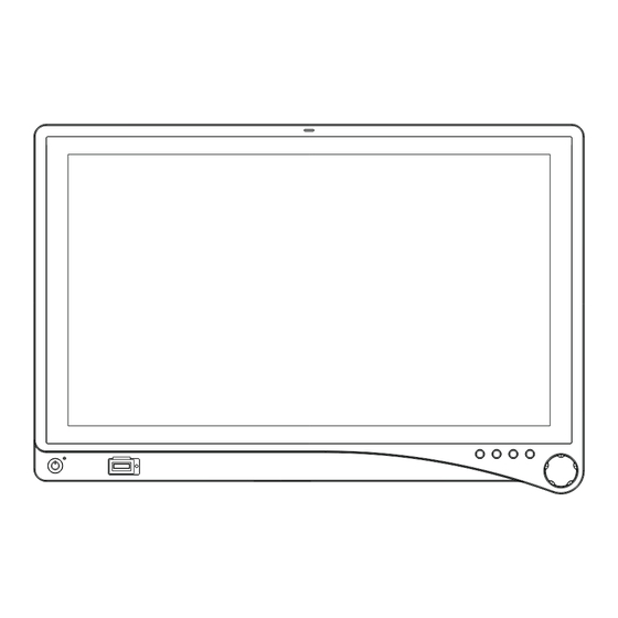
Hospital-grade AC power cord – VisionPro 26” Series Power Supply 0240-031-004 Cable Cover – Optional Accessories Part Number SYNK Wireless Transmitter 0240-031-010 SYNK Wireless Receiver 0240-031-030 SYNK Display Media Bar 0240-031-003 SYNK 26” Display Cover 0240-031-002 Hospital-grade AC power cord 15-ft. - Page 8 Token slot (SYNK Token insertion site used to establish a wireless connection VisionPro 26” Wireless with the transmitter. LED Display only) Token LED SYNK Provides feedback when linking the display and VisionPro 26” Wireless transmitter. LED Display only) Audio/PIP VisionPro 26” LED Display: Press once for the Picture in Picture adjustment menu.
- Page 9 Handles Aid in display positioning. Note: The handles are not intended to bear the entire weight of the display Cable-management cover Covers cables. Cable Cover Installing the Cable Cover Align the left and right hinges of the cable cover onto the bottom rear of the display. Snap on the top section of the cable cover to the aligning clips.
- Page 10 Display Handles Note: The handles are intended to aid in positioning the display, not for transporting the display. The handles should not bear the full weight of the display. Removing or Reinstalling the Display Handles To Remove: Using a Philips screwdriver, loosen the two **(insert size)** screws and gently pull the handle away from the display.
-
Page 11: Setup
Setup Stryker Endoscopy considers instructional training, or inservice, an integral part of this device. Your local Stryker Endoscopy sales representative will perform at least one inservice at your convenience to help set up your device and instruct on its operation and maintenance. To schedule an inservice, contact your local Stryker Endoscopy representative after your device has arrived. - Page 12 Connecting the VisionPro 26” LED Display Power Supply Connect the power supply to the 24V input on the display. Connect the AC power cord to the power supply*. Connect the AC power, using the supplied hospital-grade power cord. (Optional, not shown) Connect an extension cord between the power supply and display. Install cable cover.
-
Page 13: Basic Video Setup
Basic Video Setup Remove the cover from the cables on the rear of the display. Route the video output 1 from the camera to the SDC DVI input. Route the video output 1 from the SDC DVI output to the DVI input on the display. Reinstall the cable cover. -
Page 14: Operation
Operation Operate the display using the rotary control and the four buttons located on the front panel. A list of the display controls and their functions is provided below. On-Screen Display (OSD) Accessing the On-Screen Display To use the four front-panel buttons: Audio/PIP: Press once to activate the Audio menu (if optional Media Bar is installed), Press twice to activate Picture Mode (Picture in Picture, Picture by Picture, Picture on Picture) -
Page 15: Osd Menus
Press the Rotary Control to activate the OSD menu. Rotate the Rotary Control to move up or down through the menu. The parameter will be highlighted when selected. Press the Rotary Control to enter the next level OSD. Rotate the Rotary Control to increase or decrease the value of the selected parameter, or to make a selection on diff erent options. - Page 16 Setting Menu Item Description Range Brightness Increases or decreases the 0 – 100 brightness Contrast Increases or decreases the 0 – 100 contrast Phase** Increases or decreases the 0 – 100 Phase level Chroma** Increases or decreases the 0 – 100 Chroma level Image Sharpness Sets image sharpness 1 – 10 Video Sharpness** Increases or decreases the...
-
Page 17: Troubleshooting
Menu Item Description OSD Control Controls OSD Menu Position, Background, and Time out Restore Factory Settings Sets to factory default Screen Control*** Controls and adjusts Horizontal, Vertical, Frequency, and Phase *** Only available under analog inputs under certain respective inputs. SYNK (for the SYNK VisionPro 26”... - Page 18 Problem Current Status Remedy No picture Power LED on Using the OSD Menu, adjust the brightness and contrast to maximum, or reset them to their default settings. Power LED off Ensure the power switch at the front and rear of the display are set to ON. Check if the AC power cord is properly connected to the AC adapter and outlet.
-
Page 19: Cleaning And Maintenance
Cleaning and Maintenance Warning • To avoid electric shock and potentially fatal injury, unplug the display from the electrical outlet before cleaning. Caution • Do not spray cleaning liquid directly onto the display as product damage may result. Spray on the cloth before wiping the unit. •... -
Page 20: Technical Specifi Cations
Technical Specifi cations Display LCD Display Panel 26” (661 mm) Diagonal (a-Si TFT active matrix LCD) Synchronization 2.5 – 5.0 Vpp separated sync Pixel Pitch 0.300 (H) x 0.300 (V) mm Response Time < 18 ms Typ Viewing Angle Right/Left/Up/Down 89 Degrees Display Colors 1 billion colors (10 bit) Native Resolution 1920 (H) dots × 1080 (V) lines Input Signal... -
Page 21: Electromagnetic Compatibility
IC Regulations IC: 4919C-0240031000 (SYNK VisionPro 26” Wireless LED Display) Note: Please contact your local Stryker Endoscopy sales representative for information on changes and new products. Electromagnetic Compatibility Like other electrical medical equipment, the VisionPro 26” LED Display requires special precautions to ensure electromagnetic compatibility with other electrical medical operated according to the EMC information provided in this manual. - Page 22 Guidance and Manufacturer’s Declaration: Electromagnetic Emissions The VisionPro 26” LED Display is intended for use in the electromagnetic environment specifi ed below. The customer or the user of the display should ensure it is used in such an environment. Emissions test Compliance Electromagnetic Environment - guidance RF emissions CISPR 11...
- Page 23 Guidance and Manufacturer’s Declaration: Electromagnetic Immunity The VisionPro 26” LED Display is intended for use in the electromagnetic environment specifi ed below. The customer or the user of the display should ensure that it is used in such an environment. Immunity Test IEC 60601 Test level Compliance Level...
- Page 24 For transmitters rated at a maximum output power not listed above, the recommended separation distance (d) in meters (m) can be estimated using the equation applicable to the frequency of the transmitter, where P is the maximum output power rating of the transmitter in watts (W) according to the transmitter manufacturer. Note 1: At 80 MHz and 800 MHz, the separation distance for the higher frequency range applies.
-
Page 25: Symbols
Symbols The following symbols appear on the product, its labeling, or the product packaging. Each ned below: Direct Current For Indoor Use Only Do Not Get Device Wet DC Power Control Switch Maximum Stacking This Side Up Wireless Transmission Fragile IP23 Tested to comply with FCC Degrees of protection against the... - Page 26 Stryker Endoscopy 5900 Optical Court San Jose, CA 95138 USA 1-408-754-2000, 1-800-624-4422 www.stryker.com European Representative: Regulatory Manager, Stryker France ZAC Satolas Green Pusignan Av. De Satolas Green 69881 MEYZIEU Cedex, France P22286A 2012/11...
Need help?
Do you have a question about the 0240-031-000 and is the answer not in the manual?
Questions and answers