Table of Contents
Advertisement
Advertisement
Table of Contents

Related Manuals for Stryker VisionPro


Summary of Contents for Stryker VisionPro
- Page 1 VisionPro 26” LED Display 0240-031-020...
-
Page 2: Table Of Contents
Table of Contents Warnings and Cautions ....................1 About Your Device .....................3 Intended Use ........................3 Indications ..........................3 Contraindications ........................3 Package Contents .......................4 Device Features........................5 Setup ..........................9 Connections ..........................9 Basic Video Setup ......................11 Operation ......................... 12 On-Screen Display (OSD) ....................12 OSD Menus ......................... -
Page 3: Warnings And Cautions
Do not attempt internal repairs or adjustments not specifi cally detailed in this manual. Ensure that readjustments, modifi cations, and/or repairs are carried out by persons authorized by Stryker Endoscopy. 10. Do not put any liquid or solid object into the panel. If this occurs, unplug the device and have it checked by qualifi ed personnel before operating it any further. - Page 4 Never operate the device immediately after transportation from a cold location to a warm location. To connect to an international power supply, use an attachment plug appropriate for the cations" section of this manual. Unplug the device if it is not to be used for an extended period of time. To disconnect the rst, then pull the cord out by the plug.
-
Page 5: About Your Device
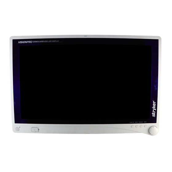
VisionPro 26” LED Display REF: 0240-031-020 The VisionPro 26” LED Display is a wide screen LED surgical display that can support a maximum resolution of WUXGA (1920x1200). The display supports various video inputs, including digital RGB, analog RGB, serial digital interface (SDI), component video (YPbPr/RGBS), S-video, and C-video. -
Page 6: Package Contents
Package Contents Reference Part Number Package Contents 0240-031-020 VisionPro 26” LED Display – (4) M4 × 16 mm VESA screws – Hospital-grade AC power cord 0240-031-004 Medical Power Supply – Cable Cover Part Number Optional Accessories 0240-031-002 VisionPro 26” Display Cover 0240-030-951 15-ft. -
Page 7: Device Features
Device Features Front panel Operate the display using the rotary control located on the front panel. A list of the display controls and their functions is provided below. Auxilliary device status LED shines red to indicate an active connection to a indicator connected device. - Page 8 Rear panel Accessory mount Provides an access point for mounting optional accessories. VESA mounting holes Provide access points for mounting the display. Power switch (hard) Powers the input DC power ON and OFF. Power connector Connects to the 24V DC power supply. Handles Aid in display positioning.
- Page 9 Cable Cover Installing the Cable Cover Align the left and right hinges of the cable cover onto the bottom rear of the display. Snap on the top section of the cable cover to the aligning clips. With your fi ngers, turn the thumbscrews clockwise to tighten and lock the cable cover onto the display.
- Page 10 Display Handles Caution: The handles are intended to aid in positioning the display, not for transporting the display. The handles should not bear the full weight of the display. Removing or Reinstalling the Display Handles To Remove: Using a 3mm hex key, loosen the two M4 x 30mm screws and gently pull the handle away from the display.
-
Page 11: Setup
Setup Stryker Endoscopy considers instructional training, or inservice, an integral part of this device. Your local Stryker Endoscopy sales representative will perform at least one inservice at your convenience to help set up your device and instruct you and your staff on its operation and maintenance. To schedule an inservice, contact your local Stryker Endoscopy representative after your device has arrived. - Page 12 Connecting the Power Supply Connect the power supply to the 24V input on the display. Connect the AC power cord to the power supply*. Connect the AC power, using the supplied hospital-grade power cord. (Optional, not shown) Connect an extension cord between the power supply and display. Install cable cover.
-
Page 13: Basic Video Setup
Basic Video Setup Route the video output 1 from the camera to the SDC DVI input. Route the video output 1 from the SDC DVI output to the DVI input on the display. -
Page 14: Operation
Operation Operate the display using the rotary control and the four buttons located on the front panel. A list of the display controls and their functions is provided below. On-Screen Display (OSD) Accessing the On-Screen Display To use the four front-panel buttons: Note: Use the Rotary Control to navigate the menus once they are activated. - Page 15 Operating On-Screen Display The device OSD helps navigate through various device menus. Press the Rotary Control to activate the OSD menu. Rotate the Rotary Control to move up or down through the menu. The parameter will be highlighted when selected. Press the Rotary Control to enter the next level OSD.
-
Page 16: Osd Menus
OSD Menus Speciality Menu Item Description Range Color Temperature* Chooses between color temperatures for Lap A, Lap B, — Standard, Arthro, PACS, NORM, ENT, GYN. Red balance -128 – 127 Green Green balance -128 – 127 Blue Blue balance -128 – 127 Gamma Gamma value 0.1 – 2.5, S0, S1, S2 Color Temperature RGB adjustment is available only for Standard, Arth, and Lap settings. - Page 17 Menu Item Description Auto Source Select Scans inputs until an active video source is detected. Sleep Timer On: The display enters sleep mode if no active video source is detected. Off : The display will not enter sleep mode. Timer: Set the time until the display enters sleep mode: 30, 60, 90, or 120 minutes.
-
Page 18: Troubleshooting
Troubleshooting Before returning your display for service, consult the troubleshooting list below: Problem Current Status Remedy No picture Power LED on Using the OSD Menu, adjust the brightness and contrast to maximum, or reset them to their default settings. Power LED off Ensure the power switch at the front and rear of the display are set to ON. -
Page 19: Cleaning And Maintenance
Cleaning and Maintenance Warning To avoid electric shock and potentially fatal injury, unplug the display from the electrical outlet before cleaning. Caution • Do not spray cleaning liquid directly onto the display as product damage may result. Spray on the cloth before wiping the unit. •... -
Page 20: Technical Specifi Cations
cations Display (a-Si TFT active matrix LCD) Viewing Angle Right/Left/Up/Down 89 Degrees Electrical Power Adapter Input: 100 – 240 VAC; 50 – 60 Hz; 2.5 A Output: 24V DC; 6.25A (150W Max) Model Number: BPM150S24F11 Power Consumption 35 - 65 Watts (approximate) Current/Voltage Rating Please ensure the respective power cord complies with applicable local regulations and... -
Page 21: Electromagnetic Compatibility
Electromagnetic Compatibility Like other electrical medical equipment, the VisionPro 26” LED Display requires special precautions to ensure electromagnetic compatibility with other electrical medical devices. according to the EMC information provided in this manual. The display has been designed and tested to comply with IEC 60601-1-2 requirements for EMC with other devices. - Page 22 Guidance and Manufacturer’s Declaration — Electromagnetic Immunity The VisionPro 26” LED Display is intended for use in the electromagnetic environment specifi ed below. The customer or the user of the display should ensure that it is used in such an environment.
- Page 23 RF transmitters, an electromagnetic site survey should be considered. If the measured fi eld strength in the location in which the VisionPro 26” LED Display is used exceeds the applicable RF compliance level above, the display and transmitter should be observed to verify normal operation. If abnormal performance is observed, additional measures may be necessary, such as reorienting or relocating the VisionPro 26”...
-
Page 24: Symbols And Defi Nitions
nitions The following symbols appear on the product, its labeling, or the product packaging. Each ned below: Attention: See Instructions for Use Consult Instructions for Use Serial Number Direct Current Authorized European Quantity Representative Catalog number Made in Country of Origin Korea Date of Manufacture Legal manufacturer... - Page 26 Produced for: Stryker Endoscopy 5900 Optical Court San Jose, CA 95138 USA 1-408-754-2000, 1-800-624-4422 www.stryker.com European Representative: Regulatory Manager, Stryker France ZAC Satolas Green Pusignan Av. De Satolas Green 69881 MEYZIEU Cedex, France P22286A 2013/02...
Need help?
Do you have a question about the VisionPro and is the answer not in the manual?
Questions and answers