Table of Contents
Advertisement
Quick Links
SCALANCE X-100 media converter
SIMATIC NET
Industrial Ethernet switches
SCALANCE X-100 media converter
Operating Instructions
04/2016
C79000-G8976-C346-02
Introduction
Network topologies
Description of the device
___________________
Installation
___________________
Connecting up
___________________
Maintenance
___________________
Technical specifications
___________________
Approvals
___________________
Dimension drawings
___________________
___________________
___________________
1
2
3
4
5
6
7
8
9
Advertisement
Table of Contents

Related Manuals for Siemens SCALANCE X101-1


Summary of Contents for Siemens SCALANCE X101-1
- Page 1 Introduction SCALANCE X-100 media converter Network topologies Description of the device ___________________ SIMATIC NET Installation ___________________ Industrial Ethernet switches SCALANCE X-100 media converter Connecting up ___________________ Maintenance ___________________ Operating Instructions Technical specifications ___________________ Approvals ___________________ Dimension drawings ___________________ ___________________ ___________________ 04/2016 C79000-G8976-C346-02...
-
Page 2: Legal Information
Note the following: WARNING Siemens products may only be used for the applications described in the catalog and in the relevant technical documentation. If products and components from other manufacturers are used, these must be recommended or approved by Siemens. Proper transport, storage, installation, assembly, commissioning, operation and maintenance are required to ensure that the products operate safely and without any problems. -
Page 3: Table Of Contents
Description of the device ........................15 Overview of the SCALANCE X-100 media converters ............15 Product characteristics......................16 3.2.1 SCALANCE X101-1 ........................ 16 3.2.2 SCALANCE X101-1LD ......................17 TP ports (twisted pair) ......................18 FO port (fiber optic) ......................... 20 3.4.1... - Page 4 Table of contents SCALANCE X101-1LD ......................43 Approvals ............................. 47 Dimension drawings ..........................51 Index ..............................55 SCALANCE X-100 media converter Operating Instructions, 04/2016, C79000-G8976-C346-02...
-
Page 5: Introduction
6GK1970-1BA10-0AA2 French 6GK1970-1BA10-0AA4 Italian You will also find this network manual on the Internet pages of Service & Support under the following entry ID: 1172207 (http://support.automation.siemens.com/WW/view/en/1172207). You will find further information in the "System Manual Industrial Ethernet" in the Manual Collection. - Page 6 Siemens recommends strongly that you regularly check for product updates. For the secure operation of Siemens products and solutions, it is necessary to take suitable preventive action (e.g. cell protection concept) and integrate each component into a holistic, state-of-the-art industrial security concept.
-
Page 7: On The Product
Introduction 1.2 On the product On the product What is possible? The media converters of the SCALANCE X-100 allow the cost-effective installation of Industrial Ethernet linear (bus) and star structures with transitions from one media to another. The passive use of two identical SCALANCE X-100 media converters in series (cascaded) within a redundant ring is possible. - Page 8 Introduction 1.2 On the product WARNING Ambient temperature above 55 °C If a device is operated in an ambient temperature of more than 55 °C, the temperature of the device housing may be higher than 70 °C. The device must therefore be installed so that it is only accessible to service personnel or users that are aware of the reason for restricted access and the required safety measures at an ambient temperature higher than 55 °C.
- Page 9 Introduction 1.2 On the product Unpacking and checking WARNING Do not use any parts that show evidence of damage If you use damaged parts, there is no guarantee that the device will function according to the specification. If you use damaged parts, this can lead to the following problems: •...
- Page 10 Introduction 1.2 On the product SCALANCE X-100 media converter Operating Instructions, 04/2016, C79000-G8976-C346-02...
-
Page 11: Network Topologies
Keep to the maximum permitted cable lengths of the devices you are using. You will find the permitted cable lengths in the section "Technical specifications (Page 41)". Bus topology Figure 2-1 Example of an electrical/optical bus topology with SCALANCE X101-1 SCALANCE X-100 media converter Operating Instructions, 04/2016, C79000-G8976-C346-02... - Page 12 A SCALANCE W access point and SIMATIC NET 200 systems are electrically connected via the media converters SCALANCE X101-1 or SCALANCE X101-1LD. Figure 2-2 Example of an optical star topology with SCALANCE X101-1 or SCALANCE X101-1LD SCALANCE X-100 media converter Operating Instructions, 04/2016, C79000-G8976-C346-02...
- Page 13 SCALANCE X208 IE switches. Using the media converters SCALANCE X101- 1 or SCALANCE X101-1LD, there is a conversion to an optical section. Figure 2-3 Example of an electrical ring with SCALANCE X101-1 or SCALANCE X101-1LD SCALANCE X-100 media converter Operating Instructions, 04/2016, C79000-G8976-C346-02...
-
Page 14: Coupling Of Network Segments
2.2 Coupling of network segments Coupling of network segments The example of a coupling between two ring networks using two SCALANCE X101-1 media converters is only indirectly possible via nodes capable of redundancy (e.g. SCALANCE X- 400). This applies to all SCALANCE X-100 media converters. -
Page 15: Description Of The Device
Description of the device Overview of the SCALANCE X-100 media converters Table 3- 1 Overview of the product characteristics Properties X101-1 X101-1LD SIMATIC environment Diagnostics LED 24 VDC 2 x 24 VDC Compact housing 40 mm (securing collar, etc.) Signaling contact + on-site operation Diagnostics: Web, SNMP, PROFINET C-PLUG Ring redundancy with RM... -
Page 16: Product Characteristics
Product characteristics 3.2.1 SCALANCE X101-1 Possible attachments The SCALANCE X101-1 media converter has an RJ-45 jack and a BFOC socket for connecting end devices or further network segments. Note The BFOC socket (Bayonet Fiber Optic Connector) corresponds to the ST socket. -
Page 17: Scalance X101-1Ld
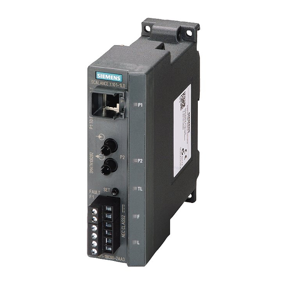
Description of the device 3.2 Product characteristics 3.2.2 SCALANCE X101-1LD Possible attachments The SCALANCE X101-1LD media converter has an RJ-45 jack and a BFOC socket for connecting end devices or further network segments. Note The BFOC socket (Bayonet Fiber Optic Connector) corresponds to the ST socket. Figure 3-2 SCALANCE X101-1LD SCALANCE X-100 media converter... -
Page 18: Tp Ports (Twisted Pair)
Description of the device 3.3 TP ports (twisted pair) TP ports (twisted pair) RJ-45 connector pinout With SCALANCE X-100 media converters, the twisted-pair port is designed as an RJ-45 jack with the MDI-X pin assignment (Medium Dependent Interface Autocrossover) of a network component. - Page 19 Description of the device 3.3 TP ports (twisted pair) Two components connected to a link segment can exchange information about the data transfer and can adapt their settings to each other. The mode with the highest possible speed is set. Note Devices not supporting autonegotiation must be set permanently to 100 Mbps half duplex or 10 Mbps half duplex.
-
Page 20: Fo Port (Fiber Optic)
Close unused optical sockets and plugs as well as pluggable transceivers and slots with the supplied protective caps. Remove the protective caps only immediately before you use the plug-in connection. 3.4.1 SCALANCE X101-1 Transmission speed The transmission speed of the optical Fast Ethernet port is 100 Mbps. Transmission mode The transmission mode for 100Base-FX is specified in the IEEE 802.3 standard. -
Page 21: Scalance X101-1Ld
Description of the device 3.4 FO port (fiber optic) 3.4.2 SCALANCE X101-1LD Transmission speed The transmission speed of the optical Fast Ethernet port is 100 Mbps. Transmission mode The transmission mode for 100Base-LX is specified in the IEEE 802.3 standard. Since the full duplex mode and the transmission speed cannot be modified for optical transmission, autonegotiation cannot be used. -
Page 22: Leds
Description of the device 3.5 LEDs LEDs Fault LED "F" (red LED) The fault LED indicates the incorrect functioning of the device. LED color LED status Meaning The SCALANCE X-100 media converter detects a fault. At the same time, the signal- ing contact opens. - Page 23 Description of the device 3.5 LEDs Note In standalone mode, the link status of the port LEDs is only displayed if the same link status is detected at both ports P1 and P2. In transparent link mode, the link status at the optical port (P2) is detected and displayed even without a link at the electrical port P1.
-
Page 24: Set Button
Description of the device 3.6 SET button SET button Function With the SET button, you can display and change the set fault mask. You can also set the transparent link mode if the media converter supports cascading. For more detailed information, refer to the section "Cascade (Page 26)". - Page 25 Description of the device 3.6 SET button Note If an empty fault mask is set or needs to be set, the 2 port LEDs flash alternately. If the fault mask is empty, no port is monitored. Error/fault If the link is lost at a monitored port or a monitored power supply is lost, this is signaled as follows: ●...
-
Page 26: Cascading Two Media Converters
Description of the device 3.7 Cascading two media converters Cascading two media converters If you cascade two media converters; in other words, connect them via the FO port, the transparent link mode must be enabled first using the SET button. You will find further information in the section "SET button (Page 24)". -
Page 27: Installation
Installation Types of installation The devices can be installed in the following ways: ● Installation on a 35 mm DIN rail ● Installation on a SIMATIC S7-300 standard rail ● Wall mounting Installation clearance Keep to the minimum clearances so that the convection ventilation of the device is not blocked. -
Page 28: Installation On A Din Rail
Installation 4.2 Installation on a DIN rail Installation on a DIN rail Installation To install the device on a 35 mm DIN rail, follow the steps below: 1. Place the second housing guide of the device on the top edge of the DIN rail. 2. - Page 29 Installation 4.2 Installation on a DIN rail Removal To remove the device from the DIN rail, follow the steps below: 1. Disconnect all connected cables. 2. Pull out the terminal blocks for the power supply and the signaling contact. 3. Release the DIN rail catch on the bottom of the device using a screwdriver. 4.
-
Page 30: Installation On A Standard Rail
Installation 4.3 Installation on a standard rail Installation on a standard rail Installation on a SIMATIC S7-300 standard rail To install the device on an S7-300 standard rail, follow the steps below: 1. Place the first housing guide of the housing on the top edge of the S7-300 standard rail. 2. -
Page 31: Wall Mounting
Installation 4.4 Wall mounting Wall mounting To mount the device on a wall, you require the following: ● 4 wall plugs, 6 mm in diameter and 30 mm long ● 4 screws 3.5 mm in diameter and 40 mm long To mount the device on a wall, follow the steps below: 1. - Page 32 Installation 4.4 Wall mounting SCALANCE X-100 media converter Operating Instructions, 04/2016, C79000-G8976-C346-02...
-
Page 33: Connecting Up
Connecting up Wiring rules When wiring use cables with the following AWG categories or cross sections. Wiring rules for ... Screw/spring-loaded termi- nals connectable cable cross sec- without wire end ferrule 0.25 - 2.5 mm tions for flexible cables ... AWG: 24 - 13 with wire end ferrule with plastic fer- 0.25 - 2.5 mm... - Page 34 Connecting up 5.2 Power supply Pin number Assignment Pin 1 L1+ (24 VDC) Pin 2 M1 (ground) Pin 3 M2 (ground) Pin 4 L2+ (24 VDC) WARNING Incorrect power supply The power supply unit to supply the device must comply with NEC Class 2 (voltage range 18 - 32 V, current requirement 350 mA).
-
Page 35: Signaling Contact
Connecting up 5.3 Signaling contact Signaling contact The signaling contact is connected to a 2-pin plug-in terminal block. The signaling contact (optical relay contact) is a floating switch with which error/fault states can be signaled by breaking the contact. NOTICE Damage due to voltage being too high The signaling contact can be subjected to a maximum load of 100 mA (safety extra-low voltage SELV, 24 VDC). -
Page 36: Grounding
Connecting up 5.4 Grounding Grounding Installation on a DIN rail The device is grounded over the DIN rail. S7 standard rail The device is grounded over its rear panel and the neck of the screw. Wall mounting The device is grounded by the securing screw in the unpainted hole. Note that the device must be grounded over a securing screw with as low a low resistance as possible. - Page 37 Connecting up 5.5 IE FC RJ-45 Plug 180 Plugging in the IE FC RJ45 Plug 180 Plug the IE FC RJ45 Plug 180 into the twisted-pair port of the device until it locks in place. Figure 5-2 Plugging in the IE FC RJ45 Plug 180 With its tight fit and locking mechanism with the PROFINET-compliant male connector IE FC RJ45 Plug 180, the securing collar on the TP port of the device ensures a rugged node attachment that provides strain and bending relief for the RJ-45 jack.
- Page 38 Connecting up 5.5 IE FC RJ-45 Plug 180 SCALANCE X-100 media converter Operating Instructions, 04/2016, C79000-G8976-C346-02...
-
Page 39: Maintenance
30 minutes before turning it on again. Device defective If any other fault develops, please send the device to your SIEMENS service center for repair. Repairs on-site are not possible. SCALANCE X-100 media converter... - Page 40 Maintenance SCALANCE X-100 media converter Operating Instructions, 04/2016, C79000-G8976-C346-02...
-
Page 41: Technical Specifications
Technical specifications SCALANCE X101-1 Table 7- 1 Technical specifications of the SCALANCE X101-1 Technical specifications Order number SCALANCE X101-1 6GK5101-1BB00-2AA3 Attachment to Industrial Ethernet Quantity Design RJ-45 jack with MDI-X pinning Properties Full duplex Transmission speed 100 Mbps Optical connectors... - Page 42 Technical specifications 7.1 SCALANCE X101-1 Technical specifications Rated voltage 24 VDC Design 4-terminal plug-in block Signaling contact Design 2-terminal plug-in block Current consumption Typical 120 mA Minimum rated current of the power 170 mA supply unit Power loss at 24 VDC...
- Page 43 Technical specifications 7.2 SCALANCE X101-1LD Note The number of SCALANCE X Industrial Ethernet devices connected in a line influences the frame delay time. When a frame runs through the SCALANCE X-100 media converter, this is delayed typically by approximately 8 µs by the cut through function of the internal switch. At 100% bus load, these times can be higher depending on the system (maximum 140 µs).
- Page 44 Technical specifications 7.2 SCALANCE X101-1LD Technical specifications Optical parameters Cable type Single mode glass FO cable Cable cross-section 10/125 μm Permitted cable length 0 to 26,000 m Attenuation ≤ 0.5 dB/km at 1310 nm 13 dB max. permitted FO cable attenuation with 2 dB link power margin Bending radius once without tensile force 100 mm...
- Page 45 Technical specifications 7.2 SCALANCE X101-1LD Technical specifications Switching properties Response to LLDP frames Blocking Response to spanning tree BPDU Forwarding frames Note The number of SCALANCE X Industrial Ethernet devices connected in a line influences the frame delay time. When a frame runs through the SCALANCE X-100 media converter, this is delayed typically by approximately 8 µs by the cut through function of the internal switch.
- Page 46 Technical specifications 7.2 SCALANCE X101-1LD SCALANCE X-100 media converter Operating Instructions, 04/2016, C79000-G8976-C346-02...
-
Page 47: Approvals
● "Industrial Ethernet / PROFINET - Passive network components" System Manual You will find information on the system manuals in the section "Auto-Hotspot", in "Further documentation". ● "EMC Installation Guidelines" configuration manual 60612658 (http://support.automation.siemens.com/WW/view/en/60612658) SCALANCE X-100 media converter Operating Instructions, 04/2016, C79000-G8976-C346-02... - Page 48 Area". You will find this document • on the data medium that ships with some devices. • on the Internet pages of Siemens Industry Online Support (http://support.automation.siemens.com/WW/view/en). Enter the document identification number C234 as the search term. The SIMATIC NET products meet the requirements of the EC directive 94/9/EC "Equipment and Protective Devices for Use in Potentially Explosive Atmospheres”.
- Page 49 Approvals IECEx The SIMATIC NET products meet the requirements of explosion protection according to IECEx. IECEx classification: Ex nA IIC T4 Gc DEK 14.0025X The products meet the requirements of the following standards: ● IEC 60079-15 (Explosive atmospheres - Part 15: Equipment protection by type of protection "n") ●...
- Page 50 Approvals Marking for the customs union EAC (Eurasian Conformity) Customs union of Russia, Belarus and Kazakhstan Declaration of the conformity according to the technical regulations of the customs union (TR CU) MSIP 요구사항 - For Korea only A급 기기(업무용 방송통신기자재) 이...
-
Page 51: Dimension Drawings
Dimension drawings Figure 9-1 Dimension drawing, rear view SCALANCE X-100 media converter Operating Instructions, 04/2016, C79000-G8976-C346-02... - Page 52 Dimension drawings Figure 9-2 Dimension drawing, side view SCALANCE X-100 media converter Operating Instructions, 04/2016, C79000-G8976-C346-02...
- Page 53 Dimension drawings Figure 9-3 Dimension drawing, bending radii...