Table of Contents
Advertisement
Available languages
Available languages
2190 Boul. Dagenais West
LAVAL (QUEBEC)
CANADA
H7L 5X9
Your pump has been carefully packaged at the
factory to prevent damage during shipping.
However, occasional damage may occur due to
rough handling. Carefully inspect your pump for
damages that could cause failures. Report any
damage to your carrier or your point of purchase.
Factory set voltage 115 V
Connection voltage changing:
Before changing the voltage connection:
A) Ensure the power to the pump is disconnected.
B) Open motor junction box cover.
C) Please select the up knob position for 115 V
or down knob position for 230 V.
D) Connect to appropriate voltage.
E) Close motor junction box.
© 2009 BUR-CAM Printed in Canada 506662
W W W. B U R C A M . C O M
TEL: 514.337.4415
FAX: 514.337.4029
info@burcam.com
INSTALLATION
INSTRUCTIONS
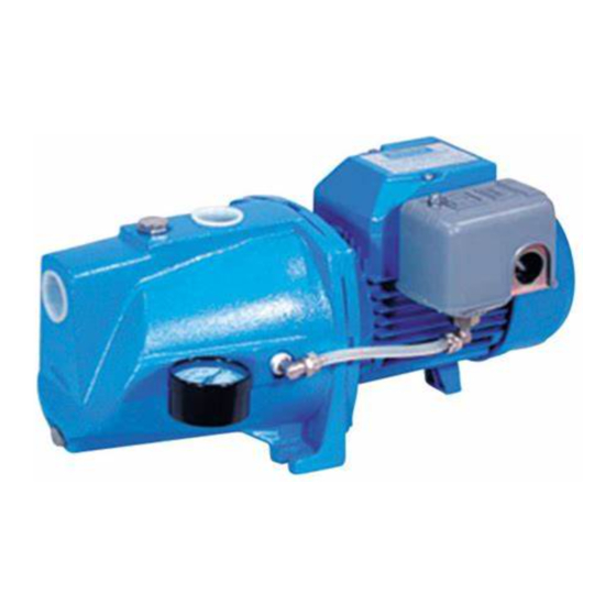
MODEL
506121S
Please read these
carefully. Failure
instructions and
may void the
JET
PUMP
instructions
to comply to
designed
operation of
this system,
warranty.
Advertisement
Table of Contents

Related Manuals for Burcam 506121S


Summary of Contents for Burcam 506121S
- Page 1 W W W. B U R C A M . C O M MODEL 2190 Boul. Dagenais West TEL: 514.337.4415 LAVAL (QUEBEC) FAX: 514.337.4029 CANADA 506121S H7L 5X9 info@burcam.com Your pump has been carefully packaged at the PUMP factory to prevent damage during shipping. However, occasional damage may occur due to rough handling.
-
Page 2: Safety Instructions
SAFETY INSTRUCTIONS: This fine pump that you have just purchased is designed from the latest in material and workmanship. Before installation and operation, we recommend the following procedures: CHECK WITH YOUR LOCAL ELECTRICAL AND PLUMBING CODES TO ENSURE YOU COMPLY WITH THE REGULATIONS. THESE CODES HAVE BEEN DESIGNED WITH YOUR SAFETY IN MIND. -
Page 3: Installation Steps
APPLICATION FEATURES Self-priming pump body. This pump is designed for shallow well installation for water level up to 25 feet. Totally enclosed, fan cooled motor, bearing to bearing. Built for a continuous use. CAPACITY AT 20 PSI: Full time connected run capacitor, to eliminate 5’... - Page 4 SHALLOW WELL APPLICATION SEE DIAGRAM ON PAGE 7 STEP 2 Cut the desired length of poly pipe to run from the top of the well to the pumping level. Smooth the pipe cuttings with your round file. (Check that no cut-out parts are left inside of pipe.
- Page 5 TANKS INSTALLATION SEE DIAGRAM ON PAGE 8 Packaged systems have the pump mounted directly to the tank. The pump to tank plumbing STEP 9 fittings are pre-assembled in factory. You only have to connect the discharge line of your for captive system to your home’s plumbing distribution line.
-
Page 6: Electrical Installation
ELECTRICAL INSTALLATION STEP 10 VOLTAGE SELECTION SWITCH 1. POWER off Electrical line from home 2. Please SELECT the up knob position for 115 V or down knob position for 230 V. distribution panel. BLACK 3. CONNECT to appropriate power source GREEN GROUND To motor lead... - Page 7 SHALLOW WELL APPLICATION STEP 5 Install your pump and thread an adaptor into inlet. STEP 6 Cut poly pipe and connect both ends. STEP 3 Insert well seal elbow thru the seal and attach to pipe. Well point optional installation STEP 7 STEP 4 You may install one or more sand...
-
Page 8: Tank Installation
To home’s plumbing distribution lineTo home’s plumbing distribution line TANK INSTALLATION Snifter valve to adjust air pressure Pressure switch 1/4” connection Pressure gauge Relief valve for pumps 1/4” connection with more than 75 PSI of capacity 1/2” connection Drain valve 1”... -
Page 9: Repair Parts
Cover box junction 20 506383 Motor flange cap screw 41 506384 Cover box screw 21 506074GP Fan cover 506121S 2009 Repair parts may be ordered from your authorized point of sale or from BUR-CAM PUMPS FOR INFORMATION TEL: 514.337.4415 FAX: 514.337.4029... - Page 10 TROUBLE SHOOTING GUIDE CHECKLIST NEVER MAKE ADJUSTMENTS TO ANY ELECTRICAL APPLIANCE OR PRODUCT WITH THE POWER CONNECTED. DON’T JUST UNSCREW THE FUSE OR TRIP THE BREAKER, REMOVE THE POWER FROM THE RECEPTACLE. TROUBLE PROBABLE CAUSE ACTION Switch is off position Turn switch to on position Motor does not run.
-
Page 11: Instructions D'installation
W W W. B U R C A M . C O M MODÈLE 2190 Boul. Dagenais Ouest TEL: 514.337.4415 LAVAL (QUÉBEC) FAX: 514.337.4029 CANADA 506121S H7L 5X9 info@burcam.com POMPE Votre pompe a été soigneusement emballée à À JET l’usine, pour prévenir les dommages possibles lors du transport. -
Page 12: Conseils De Sécurité
CONSEILS DE SÉCURITÉ: La pompe que vous venez d’acquérir est un produit fabriqué avec les meilleurs matériaux et par une main-d’oeuvre spécialisée. Veuillez suivre les instructions d’utilisation et prendre les précautions nécessaires pour votre sécurité: CONSULTEZ LES NORMES DE PLOMBERIE ET D’ÉLECTRICITÉ SE RAPPORTANT À... -
Page 13: Étapes D'installation
APPLICATION CARACTÉRISTIQUES Boîtier auto-amorçant. Cette pompe est conçue pour un puit de surface Moteur complètement fermé, refroidi par un dont le niveau d’eau est inférieur à 25 pieds. ventilateur. Roulements à billes aux deux extrémités. Fabriquée pour un usage continu. ... - Page 14 APPLICATION POUR PUITS DE SURFACE VOIR LE DIAGRAMME À LA PAGE 7 ÉTAPE 2 Couper la longueur désirée de tuyau du haut du puits au niveau de pompage. Adoucir les bouts du tuyau avec la lime ronde (Assurez-vous qu’aucun rebut de coupe ne reste à l’intérieur du tuyau.
- Page 15 INSTALLATION DES RÉSERVOIRS VOIR LE DIAGRAMME LÀ LA PAGE 8 Pour les ensembles de système d’eau dont la pompe et le réservoir ont déjà été assemblés ÉTAPE 9 en usine, le seul raccord à effectuer est de brancher la décharge de la pompe au réseau de réservoirs à...
-
Page 16: Installation Électrique
INSTALLATION ÉLECTRIQUE ÉTAPE 10 SÉLECTEUR DE VOLTAGE 1. COUPER l’alimentation électrique Alimentation électrique 3. Veuillez GLISSER vers le bas le sélecteur de voltage pour obtenir provenant du du 115 V, ou vers le haut pour le 230 V panneau de distribution. - Page 17 APPLICATION POUR PUITS DE SURFACE ÉTAPE 5 Installer votre pompe et visser un adaptateur dans la succion. ÉTAPE 6 Couper le tuyau et raccorder les extrémités. ÉTAPE 3 Insérer le coude dans le sceau d’étanchéité et le raccorder au tuyau. Installation optionnelle de pointe à...
-
Page 18: Installation Du Réservoir
INSTALLATION DU RÉSERVOIR Reniflard d’ajustement de la pression d’air Interrupteur à pression, raccord 1/4” Manomètre de pression, Valve de sécurité pour raccord 1/4” les pompes développant plus de 75 lb/po , raccord 1/2” Valve de drain, Raccord 3/4” FNPT ou raccord 1/2”... -
Page 19: Pièces De Rechange
PIÈCES DE RECHANGE Ref Pieces Descriptions Ref Pieces Descriptions 506391 Boîtier en fonte 22 506073GP Moteur du ventillateur 750769 Manomètre 23 506072GP Couvercle arrière du moteur 52319 Adaptateur en laiton 1/4”NPT1/8”B 24 506385 Rondelle ondulée à ressort 506052 Joint torique du bec de l’éjecteur 25 350335 Roulement ext.du moteur 750748... -
Page 20: Guide De Résolution Des Problèmes
GUIDE DE RÉSOLUTION DES PROBLÈMES LORS D’AJUSTEMENT SUR DES APPAREILS ÉLECTRIQUES, TOUJOURS S’ASSURER QUE LE COURANT EST DÉBRANCHÉ. NE PAS SEULEMENT ENLEVER LE FUSIBLE OU METTRE LE DISJONCTEUR HORS TENSION. IL FAUT DÉBRANCHER LE CÂBLE D’ALIMENTATION DE LA PRISE PROBLÈME CAUSE POSSIBLE ACTION Le moteur ne Commutateur hors circuit...
Need help?
Do you have a question about the 506121S and is the answer not in the manual?
Questions and answers