Advertisement
2190 Dagenais Blvd. West
Laval (Quebec)
Canada
H7L 5X9
see us at
Your pump has been carefully packaged at
the factory to prevent damage during shipping.
However, occasional damage may occur due
to rough handling. Carefully inspect your pump
for damages that could cause failures. Report any
damage to your carrier or your point of
purchase.
Factory set voltage 115 V
Connecting volatge changing :
Before changing the voltage connection :
A) Ensure the power to the pump is disconnected.
B) Open motor junction box cover.
C) Please select the up knob position for 115 V
or down knob position for 230 V.
D) Connect to appropriate power source.
E) Close motor junction box.
© 2018 BURCAM Printed in Canada 506516
Tel. : 514.337.4415
Fax : 514.337.4029
info@burcam.com
www.burcam.com
INSTALLATION
INSTRUCTIONS
MODEL
506518SS
AND BY-PRODUCTS LIKE
506537SS
506547SS
506538SS
506548SS,
506541SS
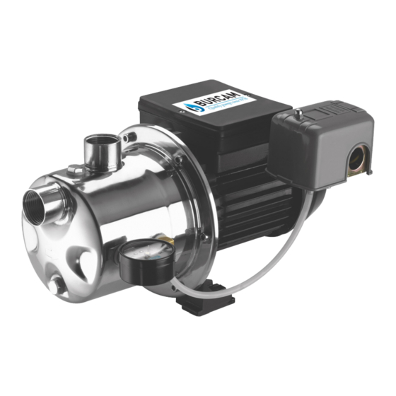
JET PUMP
Please read these
instructions carefully.
Failure to comply
to instructions
and designed
operation of
this system,
may void the
warranty.
ETC.
Advertisement
Table of Contents

Related Manuals for Burcam 506518SS


Summary of Contents for Burcam 506518SS
- Page 1 B) Open motor junction box cover. C) Please select the up knob position for 115 V or down knob position for 230 V. D) Connect to appropriate power source. E) Close motor junction box. © 2018 BURCAM Printed in Canada 506516...
-
Page 2: Safety Instructions
SAFETY INSTRUCTIONS : This fine pump that you have just purchased is designed from the latest in material and workmanship. Before installation and operation, we recommend the following procedures: CHECK WITH YOUR LOCAL ELECTRICAL AND PLUMBING CODES TO ENSURE YOU COMPLY WITH THE REGULATIONS. -
Page 3: Installation Steps
APPLICATION FEATURES This pump is designed for shallow well 304 stainless steel pump body, easy to prime. installation for a suction level up to 25 feet. Totally enclosed, fan cooled motor, Capacity at 20 PSI : bearing to bearing. - Page 4 SHALLOW WELL APPLICATION (SEE DIAGRAM ON PAGE 7) Cut the desired length of poly pipe to run from the top of the well to the pumping level. STEP 2 Smooth the pipe cuttings with your round file. (Check that no cut-out parts are left inside of pipe.
- Page 5 TANKS INSTALLATION (SEE DIAGRAM ON PAGE 8) Packaged systems have the pump mounted directly to the tank. The pump to tank plumbing STEP 9 fittings are pre-assembled in factory. You only have to connect the discharge line of your system to your home’s plumbing distribution line. When using a separate tank from your pump, we recommend to install a captive air tank as shown in our typical installation diagram, that is air injected into the tank at the factory.
-
Page 6: Electrical Installation
ELECTRICAL INSTALLATION STEP 10 VOLTAGE SELECTION SWITCH 1.POWER off 2. Please SELECT the up knob position for 115 V or down knob position for 230 V. Electrical line from home 3. CONNECT to the appropriate distribution power source. panel. BLACK TO MOTOR LEAD GREEN GROUND... - Page 7 SHALLOW WELL APPLICATION STEP 5 Install your pump and thread an adaptor into inlet. STEP 6 Cut poly pipe and connect both ends. STEP 3 Cut poly pipe and install the foot valve. Well point optionnal installation STEP 7 You may install one or more sand points STEP 4 to increase the supply of water.
-
Page 8: Tank Installation
TANK INSTALLATION Pressure switch Snifer valve to 1/4’’ connection adjust air pressure Pressure gauge 1/4’’ connection Relief valve for pumps with more than 75 PSI of capacity 1/2’’ connection Drain valve 1’’ MNPT or 3/4’’ 1/2’’ connection FNPT connection STEP 9 Connect the pump discharge to the tank ‘T’... -
Page 9: Repair Parts
510006 Impeller 32 510017 Tube 510007 Washer 33 510018 Pressure switch 510008 Mechanical seal 10 510009 Seal plate O-Ring 506518SSW 2009 Repair parts may be ordered from your authorized point of sale or from BURCAM PUMPS 506518SS version W 2009... - Page 10 TROUBLE SHOOTING GUIDE CHECKLIST NEVER MAKE ADJUSTMENTS TO ANY ELECTRICAL APPLIANCE OR PRODUCT WITH THE POWER CONNECTED. DON’T JUST UNSCREW THE FUSE OR TRIP THE BREAKER, REMOVE THE POWER FROM THE RECEPTACLE. TROUBLE PROBABLE CAUSE ACTION Switch is off position Turn switch to on position Motor does Blown fuse...
Need help?
Do you have a question about the 506518SS and is the answer not in the manual?
Questions and answers