Advertisement
Quick Links
2190 Dagenais Blvd. West
LAVAL (QUEBEC)
CANADA
H7L 5X9
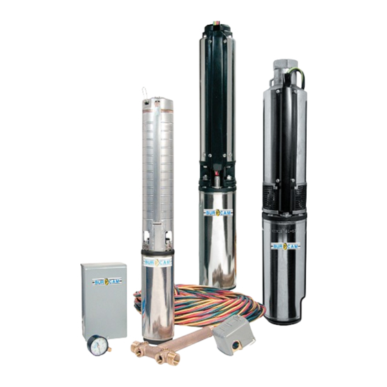
Your pump has been carefully
packaged
at
to prevent damage during
shipping. However, occasional
damage may occur due to
rough handling.
Carefully
inspect
your
pump
damages that could
cause failures. Report
any damage to your
carrier or your point
of purchase.
WWW.BURCAM.COM
TEL: 514.337.4415
FAX: 514.337.4029
info@burcam.com
the
factory
for
INSTALLATION
INSTRUCTIONS
101 / 105
SERIES
SUBMERSIBLE
DEEP WELL PUMPS
INSTRUCTIONS
INSTRUCTIONS
ARE VALID FOR
ARE VALID FOR
2 AND 3 WIRES
2 AND 3 WIRES
(+GROUND)
(+GROUND)
DEEP WELL
DEEP WELL
INSTALLATION.
INSTALLATION.
© 2015 BUR-CAM Printed in Canada 105287
or
''SUB-PACS''
Please read
these instructions
carefully. Failure
to comply to
instructions
and designed
operation of this
system, may void
the warranty.
THESE
THESE
PUMP
PUMP
Advertisement

Related Manuals for Burcam 101124


Summary of Contents for Burcam 101124
- Page 1 INSTALLATION INSTRUCTIONS WWW.BURCAM.COM 101 / 105 2190 Dagenais Blvd. West TEL: 514.337.4415 LAVAL (QUEBEC) FAX: 514.337.4029 SERIES CANADA H7L 5X9 info@burcam.com SUBMERSIBLE Your pump has been carefully DEEP WELL PUMPS packaged factory to prevent damage during ‘‘SUB-PACS’’ shipping. However, occasional damage may occur due to rough handling.
- Page 2 Safety Instructions : This fine pump that you have just purchased is manufactured with the highest quality materials and workmanship. Before installation and operation, we recommend the following procedures : CHECK WITH YOUR LOCAL ELECTRICAL AND PLUMBING CODES TO ENSURE YOU COMPLY WITH THE REGULATIONS.
-
Page 3: Installation Steps
Material required for a drilled well application Tank installation Deep well pump installation Desired length of 1” braided hose (750919) to Desired length of polyethylene 1” pipe, 100 PSI, link up from pump to tank. Keep tank as close as CSA or UL approved, to link up from pumping level possible to the pump. - Page 4 150143 / 150152 (4 tubes) (3 tubes) HEAT SHRINK SPLICING KIT SHRINKING TECHNIQUE Shrinking can be accomplished through the use of a thermo gun or flame torch with a utility head or other broad flame. Begin at one end of tubing. Keep tubing out of direct contact with flame.
-
Page 5: Electrical Installation
ELECTRICAL INSTALLATION We recommend that a licensed electrician be employed to do wiring to the pressure switch. STEP 9 Permanently ground the motor in accordance to the electrical codes for your area. Do not use an extension cord to connect your pump to the power source. From your distribution panel to the pressure switch, install a wire gauge not smaller than 14 gauge. - Page 6 STEP BY STEP INSTALLATION INSTRUCTION FOR YOUR NEW DEEP WELL PUMP Lay the pump on the ground a foot or two from the well head with the discharge end pointing STEP 1 away from the well. Connect the power cables to the motor lead using the heat shrink kit. Review the instruction on the previous page.
- Page 7 Roll out the submersible pump cable on the ground along side of your 1’’ plastic Poly pipe. STEP 7 At 5 foot intervals, using your electrical tape, tape the cable to the pipe. This will prevent the cable from hitting the well casing when lowering pump into the well. Securely attach your 1/4’’...
- Page 8 AIR PRESSURE TANK INSTALLATION When using a pressure tank with your pump, we recommend that you install a captive air STEP 10 tank where the air pressure is injected at the factory. (See our installation diagram.) This for captive air, which is in addition to atmospheric pressure, increases the ability of the tank to deliver air tanks more water between the on/off cycles.
- Page 9 AIR PRESSURE TANK INSTALLATION ‘‘ Free-Standing type tanks have to be install offset from STEP 1 L.O.P Female adaptor your pump, and in the discharge line coming from your Pressure switch #750949 #150159S. pump’s discharge connection (either a jet or a submersible pump).
- Page 10 5 GPM 1 - 1 1/4’’ DISCHARGE 5 GPM 1 - 1 1/4’’ DISCHARGE 7 GPM 1 - 1 1/4’’ DISCHARGE MODELS Wire Stages MODELS Wire Stages MODELS Wire Stages 101124 105130 105113 101125 105125 105114 101126 105132 105131 101074 105127 105163...
-
Page 11: Repair Parts
REPAIR PARTS STAINLESS STEEL SERIES STAINLESS STEEL & STAINLESS STEEL & NORYL SERIES NORYL SERIES Pump head Pump head Pump head Models Description Models Description Models Description 111127 13 stages 115307ST 6 stages 115127 13 stages 111135 18 stages 115309ST 8 stages 115135 18 stages... - Page 12 TROUBLE SHOOTING GUIDE CHECKLIST NEVER MAKE ADJUSTMENTS TO ANY ELECTRICAL APPLIANCE OR PRODUCT WITH THE POWER CONNECTED. DON’T JUST UNSCREW THE FUSE OR TRIP THE BREAKER, REMOVE THE POWER FROM THE RECEPTACLE. TROUBLE PROBABLE CAUSE ACTION Motor does not Blown fuse Replace run.
Need help?
Do you have a question about the 101124 and is the answer not in the manual?
Questions and answers