Table of Contents
Advertisement
Quick Links
Advertisement
Table of Contents

Related Manuals for Supermicro X11DAi-N


Summary of Contents for Supermicro X11DAi-N
- Page 1 X11DAi-N USER’S MANUAL Revision 1.0b...
- Page 2 State of California, USA. The State of California, County of Santa Clara shall be the exclusive venue for the resolution of any such disputes. Supermicro's total liability for all claims will not exceed the price paid for the hardware product.
-
Page 3: About This Manual
PCI-E 3.0 x16 slots, two PCI-E 3.0 x8 slots, ten SATA 3.0 connections, and LRDIMM/ RDIMM/NVDIMM DDR4 ECC 2666 MHz (max) memory in 16 memory slots. The X11DAi-N provides maximum performance, system cooling, and PCI-E capacity currently available on the market. -
Page 4: Contacting Supermicro
Super X11DAi-N User's Manual Contacting Supermicro Headquarters Address: Super Micro Computer, Inc. 980 Rock Ave. San Jose, CA 95131 U.S.A. Tel: +1 (408) 503-8000 Fax: +1 (408) 503-8008 Email: marketing@supermicro.com (General Information) support@supermicro.com (Technical Support) Website: www.supermicro.com Europe Address: Super Micro Computer B.V. -
Page 5: Table Of Contents
Table of Contents Table of Contents Chapter 1 Introduction 1.1 Checklist ..........................9 Quick Reference Table ......................12 Motherboard Features .......................14 1.2 Processor and Chipset Overview ..................18 1.3 Special Features ........................19 Recovery from AC Power Loss ..................19 1.4 System Health Monitoring ....................19 Onboard Voltage Monitors ....................19 Fan Status Monitor with Firmware Control ...............19 Environmental Temperature Control .................19... - Page 6 Super X11DAi-N User's Manual Assembly ...........................29 Attaching the Processor Package Assembly to the Heatsink to Form the Processor Heatsink Module (PHM) ....................30 Installing the Processor Heatsink Module (PHM) ............31 Removing the Processor Heatsink Module (PHM) from the Motherboard .......32 2.4 Memory Support and Installation ..................33 Memory Support ........................33...
- Page 7 Table of Contents Chapter 4 BIOS 4.1 Introduction .........................74 4.2 Main Setup .........................75 4.3 Advanced Setup Configurations ..................77 4.4 Event Logs ..........................99 4.5 IPMI ...........................101 4.7 Boot ..........................107 4.8 Save & Exit ........................110 Appendix A BIOS Codes Appendix B Software Installation B.1 Installing Software Programs ...................114 B.2 SuperDoctor 5 .........................115...
- Page 8 Notes...
-
Page 9: Chapter 1 Introduction
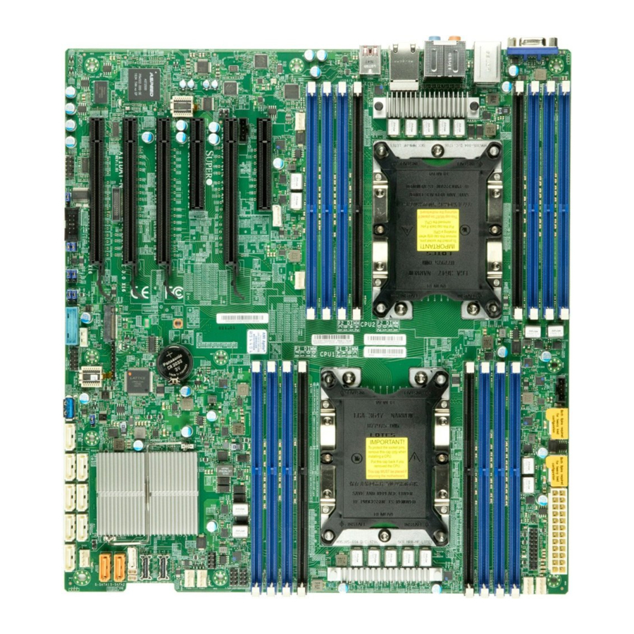
Introduction Congratulations on purchasing your computer motherboard from an industry leader. Supermicro motherboards are designed to provide you with the highest standards in quality and performance. In addition to the motherboard, several important parts that are included with your shipment are listed below. - Page 10 Super X11DAi-N User's Manual Figure 1-1. X11DAi-N Motherboard Image Note: All graphics shown in this manual were based upon the latest PCB revision available at the time of publication of the manual. The motherboard you received may or may not look exactly the same as the graphics shown in this manual.
- Page 11 Chapter 1: Introduction Figure 1-2. X11DAi-N Motherboard Layout (not drawn to scale) USB8/9 (3.1) AUDIO USB1~4 (3.0) LAN1/2 FAN6 JNCSI CPU2 FAN5 X11DAi-N REV:1.01 BAR CODE MAC CODE Battery BIOS CPU1 SATA9 SATA10 JNVME1 JNVME2 S-SATA1 S-SATA2 JSD1 JSD2 FAN4 FAN3...
-
Page 12: Quick Reference Table
NVMe SMBus (I C) headers used for PCI-E hot-plug SMBus clock & data connections (an SMCI- JNVI C1/2 proprietary NVMe add-on card and cable are required; available for a Supermicro complete system only) JNVME1/2 NVMe slots 1/2 Complex-Programmable Logical Device (CPLD) header... -
Page 13: Connector Description
Chapter 1: Introduction Connector Description General Purpose Serial I/O ports 1/2/3 (T-SGPIO1: SATA1~4, T-SGPIO2: SATA5~8, T-SGPIO3: T-SGPIO1/2/3 S-SATA1/2) USB1/2/3/4 (3.0) Backpanel USB 3.0 ports 1/2/3/4 USB7 (3.0) Front Accessible USB 3.0 Type A connector (USB 7) USB5/6 (3.0) USB 3.0 connections 5/6 for front access USB8/9 (3.1) Back panel USB 3.1 ports 8/9 VGA port on the I/O back panel... -
Page 14: Motherboard Features
DIMM Size • Up to 128 GB at 1.2V Note 1: Memory speed support depends on the processors used in the system. Note 2: For the latest CPU/memory updates, please refer to our website at http://www.supermicro.com/products/ motherboard. Chipset • Intel C621 Expansion Slots •... - Page 15 Main switch override mechanism • Power-on mode for AC power recovery • Intel® Intelligent Power Node Manager 4.0 (available when the Supermicro Power Manager [SPM] is installed and a special power supply is used) • Management Engine (ME) System Health Monitoring •...
- Page 16 User's Guide available at http://www.supermicro.com/support/manuals/. Note 3: It is strongly recommended that you change BMC log-in information upon ini- tial system power-on. The manufacture default username is ADMIN and the password is ADMIN. For proper BMC configuration, please refer to http://www.supermicro.com/ products/info/files/IPMI/Best_Practices_BMC_Security.pdf...
-
Page 17: System Block Diagram
Chapter 1: Introduction Figure 1-3. System Block Diagram X11DAI-N Block Diagram #1-8 #2-8 #1-7 #2-7 #1-6 #2-6 #1-5 #2-5 #1-4 #2-4 #1-3 #2-3 #1-2 #2-2 #1-1 #2-1 CPU CORE CPU CORE : I C DDR4 DDR4 #3AB DMI3 DMI2 PCI-E X16 G3... -
Page 18: Processor And Chipset Overview
1.2 Processor and Chipset Overview Built upon the functionality and capability of the Intel Xeon 81xx/61xx/51xx/41xx/31xx Series processors (Socket P0) and the Intel C621 chipset, the X11DAi-N motherboard provides superb system performance, efficient power management, and a rich feature set based on cutting edge technology to address the needs of next-generation computer users. -
Page 19: Special Features
Chapter 1: Introduction 1.3 Special Features This section describes the health monitoring features of the X11DAi-N motherboard. The motherboard has an onboard ASpeed AST 2500 Baseboard Management Controller (BMC) that supports system health monitoring. Recovery from AC Power Loss The Basic I/O System (BIOS) provides a setting that determines how the system will respond when AC power is lost and then restored to the system. -
Page 20: System Resource Alert
Super X11DAi-N User's Manual System Resource Alert This feature is available when used with SuperDoctor 5 . SuperDoctor 5 is used to notify the ® user of certain system events. For example, you can configure SuperDoctor 5 to provide you with warnings when the system temperature, CPU temperatures, voltages and fan speeds go beyond a predefined range. -
Page 21: Advanced Power Management
Intel's Intelligent Power Node Manager (IPNM) provides your system with real-time thermal control and power management for maximum energy efficiency. IPNM is available when the Supermicro Power Manager (SPM) is installed. Although IPNM Specification Version 2.0 or 3.0 is supported by the BMC (Baseboard Management Controller), your system must also have IPNM-compatible Management Engine (ME) firmware installed to use this feature. -
Page 22: Chapter 2 Installation
Super X11DAi-N User's Manual Chapter 2 Installation 2.1 Static-Sensitive Devices Electrostatic Discharge (ESD) can damage electronic com ponents. To avoid damaging your motherboard and your system, it is important to handle it very carefully. The following measures are generally sufficient to protect your equipment from ESD. -
Page 23: Motherboard Installation
Tools Needed Standoffs (10) Screws Only if Needed (10) USB8/9 (3.1) AUDIO USB1~4 (3.0) LAN1/2 FAN6 JNCSI CPU2 FAN5 X11DAi-N REV:1.01 BAR CODE MAC CODE Battery BIOS CPU1 SATA9 SATA10 JNVME2 JNVME1 S-SATA1 S-SATA2 JSD1 JSD2 FAN4 FAN3 FAN2... -
Page 24: Installing The Motherboard
Super X11DAi-N User's Manual Installing the Motherboard 1. Install the I/O shield into the back of the chassis. 2. Locate the mounting holes on the motherboard. See the previous page for the location. 3. Locate the matching mounting holes on the chassis. Align the mounting holes on the motherboard against the mounting holes on the chassis. -
Page 25: Processor And Heatsink Installation
CPU socket cap is in place and that none of the socket pins are bent; otherwise, contact your retailer immediately. • Refer to the Supermicro website for updates on CPU support. • Please follow the instructions given in the ESD Warning section on the first page of this chapter before handling, installing, or removing system components. -
Page 26: Overview Of The Processor Socket Assembly
Super X11DAi-N User's Manual Overview of the Processor Socket Assembly The processor socket assembly contains 1) the 81xx/61xx/51xx/41xx/31xx Processor 2) the narrow processor clip, 3) the dust cover, and 4) the CPU socket. 1. 81xx/61xx/51xx/41xx/31xx Processor 81xx/61xx/51xx/41xx/31xx (The Processor) 2. Narrow processor clip (the plastic processor package carrier used for the CPU) (The Narrow Processor Clip) 3. -
Page 27: Overview Of The Processor Heatsink Module (Phm)
Chapter 2: Installation Overview of the Processor Heatsink Module (PHM) The Processor Heatsink Module (PHM) contains 1) a heatsink, 2) a narrow processor clip, and 3) the 81xx/61xx/51xx/41xx/31xx Processor. 1. Heatsink 2. Narrow processor clip 81xx/61xx/51xx/41xx/31xx Processor Processor Heatsink Module (PHM) (Bottom View for the PHM... -
Page 28: Preparing The Cpu Socket For Installation
Super X11DAi-N User's Manual Preparing the CPU Socket for Installation This motherboard comes with the CPU socket pre-assembled in the factory. The CPU socket contains 1) a dust cover, 2) a socket bracket, 3) the CPU (P0) socket, and 4) a back plate. -
Page 29: Assembly
Chapter 2: Installation Attaching the Processor to the Narrow Processor Clip to Create the Processor Package Assembly To properly install the CPU into the narrow processor clip, please follow the steps below. 1. Locate pin 1 (notch A), which is the triangle located on the top of the narrow processor clip. -
Page 30: Attaching The Processor Package Assembly To The Heatsink To Form The Processor Heatsink Module (Phm)
Super X11DAi-N User's Manual Attaching the Processor Package Assembly to the Heatsink to Form the Processor Heatsink Module (PHM) After you have made a processor package assembly by following the instructions on the previous page, please follow the steps below to mount the processor package assembly onto the heatsink to create the Processor Heatsink Module (PHM). -
Page 31: Installing The Processor Heatsink Module (Phm)
Chapter 2: Installation Installing the Processor Heatsink Module (PHM) 1. Once you have assembled the processor heatsink module (PHM) by following the instructions listed on page 29 or page 30, you are ready to install the processor heatsink module (PHM) into the CPU socket on the motherboard. To install the PHM into the CPU socket, follow the instructions below. -
Page 32: Removing The Processor Heatsink Module (Phm) From The Motherboard
Super X11DAi-N User's Manual Removing the Processor Heatsink Module (PHM) from the Motherboard Before removing the processor heatsink module (PHM), unplug power cord from the power outlet. 1. Using a T30 Torx-bit screwdriver, turn the screws on the PHM counterclockwise to loosen them from the socket, starting with screw marked #4 (in the sequence of 4, 3, 2, 2. -
Page 33: Memory Support And Installation
Memory Support The X11DAi-N supports up to 2048 GB of Load Reduced DIMM (LRDIMM), Registered DIMM (RDIMM), Non-Volatile DIMM (NV-DIMM) DDR4 (288-pin) ECC 2133/2400/2666 MHz memory modules in 16 slots. Populating these DIMM modules with a pair of memory modules of the same type and size will result in interleaved memory, which will improve memory performance. -
Page 34: Dimm Population Requirements For The 81Xx/61Xx/51Xx/41Xx/31Xx Processors
Super X11DAi-N User's Manual DIMM Population Requirements for the 81xx/61xx/51xx/41xx/31xx Processors For optimal memory performance, follow the tables below when populating memory modules. Key Parameters for DIMM Configurations Parameters Possible Values Number of Channels 1, 2, 3, 4, 5, or 6... - Page 35 Chapter 2: Installation (DDR4 Only) Socket Level Population Requirements DDR4 Socket Level Minimum Population Requirements • There should be at least one DDR4 DIMM per socket. • If only one DIMM is populated in a channel, then populate it in the slot furthest away from CPU. •...
- Page 36 Super X11DAi-N User's Manual (DDR4 Only) 2SPC Memory Configuration with x4 DIMMs Total # of DDR Channel Number Adaptive Virtual DIMMs of Ranks Lock Step DIMM Popula- 1 x4 DIMM Must be installed on iMC0 DDR Channel 0 Y, only Bank VLS tion within an >1...
-
Page 37: Dimm Installation
DIMMB1, DIMME1 (DIMMA2 and D2 is reserved for Apache Pass memory. Standard memory can be populated in DIMMA2 and D2 but will result in decreased performance). For the system X11DAi-N REV:1.01 BAR CODE MAC CODE to work properly, please use memory modules of the same type and speed on the motherboard. -
Page 38: Rear I/O Ports
Super X11DAi-N User's Manual 2.5 Rear I/O Ports See Figure 2-2 below for the locations and descriptions of the various I/O ports on the rear of the motherboard. X11DAi-N REV:1.01 BAR CODE MAC CODE Back panel I/O Port Locations and Definitions... - Page 39 Ground feature. See the layout below for onboard Jack_Detect audio header. Line_2_Left Ground 1. VGA 2.SPDIF_Out 3. Surround_Out 4. CEN/LFE_Out 5. Mic_In 6. Line-Out X11DAi-N REV:1.01 7. Line_In BAR CODE MAC CODE 8. Audio Header...
- Page 40 Super X11DAi-N User's Manual Universal Serial Bus (USB) Ports There are four USB 3.0 ports (USB 1-4) and two USB 3.1 ports (USB 8/9) on the I/O back panel. Another USB 3.0 header, located next to the TPM/Port 80 header, also provides two USB 3.0 connections (USB 5/6) for front access.
-
Page 41: Ethernet Ports
Two Ethernet ports (LAN1, LAN2) are located on the I/O backplane. These Ethernet ports support 1 GbE LAN connections on the X11DAi-N. These Ethernet ports accept RJ45 type cables. Please refer to the LED Indicator section for LAN LED information. -
Page 42: Front Control Panel
JF1 contains header pins for various buttons and indicators that are normally located on a control panel at the front of the chassis. These connectors are designed specifically for use with Supermicro chassis. See the figure below for the descriptions of the front control panel buttons and LED indicators. -
Page 43: Power Button
Ground 1. PWR Button 2. Reset Button Power Button Ground Ground Reset Reset Button Power Fail LED 3.3V X11DAi-N OH/Fan Fail LED UID LED REV:1.01 BAR CODE MAC CODE 3.3V Stby NIC2 Active LED 3.3V Stby NIC1 Active LED 3.3V Stby... - Page 44 Super X11DAi-N User's Manual Power Fail LED The Power Fail LED connection is located on pins 5 and 6 of JF1. Refer to the table below for pin definitions. Power Fail LED Pin Definitions (JF1) Pin# Definition 3.3V PWR Supply Fail...
- Page 45 1. NIC2 LED 2. NIC1 LED 3. HDD LED Power Button Ground Ground Reset Reset Button Power Fail LED 3.3V X11DAi-N OH/Fan Fail LED UID LED REV:1.01 BAR CODE MAC CODE 3.3V Stby NIC2 Active LED 3.3V Stby NIC1 Active LED 3.3V Stby...
-
Page 46: Nmi Button
Super X11DAi-N User's Manual Power LED The Power LED connection is located on pins 15 and 16 of JF1. Refer to the table below for pin definitions. Power LED Pin Definitions (JF1) Pins Definition 3.3V PWR LED NMI Button The non-maskable interrupt (NMI) button header is located on pins 19 and 20 of JF1. Refer to the table below for pin definitions. -
Page 47: Connectors
+12V Ground +3.3V Required Connection 1. JPWR3 24-pin Power Supply USB8/9 (3.1) AUDIO USB1~4 (3.0) LAN1/2 FAN6 JNCSI CPU2 FAN5 X11DAi-N REV:1.01 BAR CODE MAC CODE Battery BIOS CPU1 SATA9 SATA10 JNVME2 JNVME1 S-SATA1 S-SATA2 JSD1 JSD2 FAN4 FAN3 FAN2... - Page 48 Super X11DAi-N User's Manual 12V 8-pin CPU Power Connectors JPWR1 and JPWR2 are the 8-pin 12V DC power input for the CPU or alternative single power source for a special enclosure when the 24-pin ATX power is not in use. Refer to the table below for pin definitions.
-
Page 49: Headers
USB8/9 (3.1) AUDIO USB1~4 (3.0) LAN1/2 3. FAN3 FAN6 4. FAN4 5. FAN5 JNCSI 6. FAN6 CPU2 7. FANA FAN5 X11DAi-N REV:1.01 BAR CODE MAC CODE Battery BIOS CPU1 SATA9 SATA10 JNVME2 JNVME1 S-SATA1 S-SATA2 JSD1 JSD2 FAN4 FAN3 SATA DOM... - Page 50 Super X11DAi-N User's Manual Serial Port There is a COM header (COM2) on the motherboard. The COM port and header provide serial communication support. See the table below for pin definitions. SPDIF_In/ SPDIF_Out Headers The SPDIF_In (JSPDIF_In) and SPDIF_Out (JSPDIF_Out) headers are located next to PCI-E Slot 5 on the motherboard.
- Page 51 SPI_CLK SPI_MOSI +3.3V Stdby SPI_IRQ# 1. TPM/Port 80 Header USB8/9 (3.1) AUDIO USB1~4 (3.0) LAN1/2 FAN6 JNCSI CPU2 FAN5 X11DAi-N REV:1.01 BAR CODE MAC CODE Battery BIOS CPU1 SATA9 SATA10 JNVME2 JNVME1 S-SATA1 S-SATA2 JSD1 JSD2 FAN4 FAN3 SATA DOM...
- Page 52 Super X11DAi-N User's Manual Disk-On-Module Power Connector The Disk-On-Module (DOM) power connectors at JSD1 and JSD2 provide 5V power to solid-state DOM storage devices connected to the SATA ports. See the table below for pin definitions. DOM PWR Pin Definitions...
- Page 53 1. RAID Key 2. T-SGPIO 1 USB8/9 (3.1) AUDIO USB1~4 (3.0) LAN1/2 3. T-SGPIO 2 FAN6 4. T-SGPIO 3 JNCSI CPU2 FAN5 X11DAi-N REV:1.01 BAR CODE MAC CODE Battery BIOS CPU1 SATA9 SATA10 JNVME2 JNVME1 S-SATA1 S-SATA2 JSD1 JSD2 FAN4 FAN3...
-
Page 54: Chassis Intrusion
Super X11DAi-N User's Manual Chassis Intrusion A Chassis Intrusion header is located at JL1 on the motherboard. Attach the appropriate cable from the chassis to inform you of a chassis intrusion when the chassis is opened. Refer to the table below for pin definitions. - Page 55 C1/2), used for PCI-E SMBus clock and data connections, provide hot-plug support via a dedicated SMBus interface. This feature is only available for a Supermicro complete system with an SMCI-proprietary NVMe add-on card and cable installed. See the table below for pin definitions.
-
Page 56: Speaker Header
Super X11DAi-N User's Manual M.2-CPU1 Slot The X11DAi-N motherboard has one M.2 slot that is supported by CPU1 (M.2-CPU1). M.2 was formerly Next Generation Form Factor (NGFF) and are used to replace mini PCI-E. M.2 supports a variety of card sizes with increased functionality and spatial efficiency. The M.2 socket on the motherboard supports PCI-E 3.0 X4 (32 Gb/s) SSD cards in the 2280 and... - Page 57 Chapter 2: Installation I-SATA 3.0 and S-SATA 3.0 Ports The X11DAi-N has eight SATA 3.0 ports (SATA1-4, 5-8) supported by the Intel PCHC620 and two S-SATA (S-SATA1/2) supported by the Intel SCU on the motherboard. S-SATA1/2 can be used with Supermicro SuperDOMs which are yellow SATA DOM connectors with power pins built in, and do not require external power cables.
-
Page 58: Jumper Settings
Super X11DAi-N User's Manual 2.8 Jumper Settings How Jumpers Work To modify the operation of the motherboard, jumpers can be used to choose between optional settings. Jumpers create Connector Pins shorts between two pins to change the function of the connector. - Page 59 Do not use the PW_ON connector to clear CMOS. JBT1 contact pads 1. Clear CMOS USB8/9 (3.1) AUDIO USB1~4 (3.0) LAN1/2 FAN6 JNCSI CPU2 FAN5 X11DAi-N REV:1.01 BAR CODE MAC CODE Battery BIOS CPU1 SATA9 SATA10 JNVME1 JNVME2 S-SATA1 S-SATA2...
- Page 60 Super X11DAi-N User's Manual Management Engine (ME) Recovery Use jumper JPME1 to select ME Firmware Recovery mode, which will limit resource allocation for essential system operation only in order to maintain normal power operation and management. In the single operation mode, online upgrade will be available via Recovery mode.
- Page 61 Pins 1-2 Reset Pins 2-3 Open Disabled 1. Watch Dog USB8/9 (3.1) AUDIO USB1~4 (3.0) LAN1/2 FAN6 JNCSI CPU2 FAN5 X11DAi-N REV:1.01 BAR CODE MAC CODE Battery BIOS CPU1 SATA9 SATA10 JNVME2 JNVME1 S-SATA1 S-SATA2 JSD1 JSD2 FAN4 FAN3 FAN2...
- Page 62 Super X11DAi-N User's Manual C Bus for VRM Jumpers JVRM1 and JVRM2 allow the VRM SMB Clock and Data to access the Baseboard Management Controller (BMC). See the tables below for jumper settings. JVRM1 (VRM SMB Clock to BMC) Jumper Settings...
-
Page 63: Led Indicators
Green 100 Mb/s Amber 1 Gb/s 1. LAN1/LAN2 LEDs USB8/9 (3.1) AUDIO USB1~4 (3.0) LAN1/2 FAN6 JNCSI CPU2 FAN5 X11DAi-N REV:1.01 BAR CODE MAC CODE Battery BIOS CPU1 SATA9 SATA10 JNVME1 JNVME2 S-SATA1 S-SATA2 JSD1 JSD2 FAN4 FAN3 SATA DOM... - Page 64 Super X11DAi-N User's Manual BMC Heartbeat LED LEDM1 is the BMC heartbeat LED. When the LED is blinking green, BMC is functioning normally. See the table below for the LED status. Onboard Power LED Indicator LED Color Definition Green: BMC Normal...
- Page 65 A power LED indicator is located at LE3. When this LED is on, system power is on. See the layout below for the location of LE3 1. Power LED (LE3) USB8/9 (3.1) AUDIO USB1~4 (3.0) LAN1/2 FAN6 JNCSI CPU2 FAN5 X11DAi-N REV:1.01 BAR CODE MAC CODE Battery BIOS CPU1 SATA9 SATA10 JNVME2 JNVME1 S-SATA1 S-SATA2...
-
Page 66: Chapter 3 Troubleshooting
Super X11DAi-N User's Manual Chapter 3 Troubleshooting 3.1 Troubleshooting Procedures Use the following procedures to troubleshoot your system. If you have followed all of the procedures below and still need assistance, refer to the ‘Technical Support Procedures’ and/ or ‘Returning Merchandise for Service’ section(s) in this chapter. Always disconnect the AC power cord before adding, changing or installing any non hot-swap hardware components. -
Page 67: No Video
Chapter 3: Troubleshooting No Video 1. If the power is on but you have no video, remove all the add-on cards and cables. 2. Use the speaker to determine if any beep codes exist. Refer to Appendix A for details on beep codes. -
Page 68: Losing The System's Setup Configuration
Super X11DAi-N User's Manual Losing the System's Setup Configuration 1. Make sure that you are using a high quality power supply. A poor quality power supply may cause the system to lose the CMOS setup information. Refer to Section 1.6 for details on recommended power supplies. - Page 69 Chapter 3: Troubleshooting 3. Using the minimum configuration for troubleshooting: Remove all unnecessary components (starting with add-on cards first), and use the minimum configuration (but with a CPU and a memory module installed) to identify the trouble areas. Refer to the steps listed in Section A above for proper troubleshooting procedures.
-
Page 70: Technical Support Procedures
Super X11DAi-N User's Manual 3.2 Technical Support Procedures Before contacting Technical Support, please take the following steps. Also, note that as a motherboard manufacturer, we do not sell directly to end-users, so it is best to first check with your distributor or reseller for troubleshooting services. They should know of any possible problem(s) with the specific system configuration that was sold to you. -
Page 71: Frequently Asked Questions
3.3 Frequently Asked Questions Question: What type of memory does my motherboard support? Answer: The X11DAi-N motherboard supports up to 1536 GB of Load Reduced DIMM (LRDIMM), 3D LRDIMM, Non-Volatile DIMM (NV-DIMM) DDR4 (288-pin) ECC of up to 2666 MHz modules in 16 slots. See Section 2.4 for details on installing memory. -
Page 72: Battery Removal And Installation
Super X11DAi-N User's Manual 3.4 Battery Removal and Installation Battery Removal To remove the onboard battery, follow the steps below: 1. Power off your system and unplug your power cable. 2. Using a tool such as a pen or a small screwdriver, push the battery lock outwards to unlock it. -
Page 73: Returning Merchandise For Service
Shipping and handling charges will be applied for all orders that must be mailed when service is complete. For faster service, RMA authorizations may be requested online (http://www.supermicro.com/ support/rma/). This warranty only covers normal consumer use and does not cover damages incurred in shipping or from failure due to the alteration, misuse, abuse or improper maintenance of products. -
Page 74: Chapter 4 Bios
X11DAi-N User's Manual Chapter 4 BIOS 4.1 Introduction This chapter describes the AMIBIOS™ Setup utility for the motherboard. The BIOS is stored on a chip and can be easily upgraded using a flash program. Note: Due to periodic changes to the BIOS, some settings may have been added or deleted and might not yet be recorded in this manual. -
Page 75: Main Setup
Note: The time is in the 24-hour format. For example, 5:30 P.M. appears as 17:30:00. The date's default value is 01/01/2015 after RTC reset. Supermicro X11DAi-N BIOS Version This item displays the version of the BIOS ROM used in the system. - Page 76 X11DAi-N User's Manual Memory Information Total Memory This item displays the total size of memory available in the system.
-
Page 77: Advanced Setup Configurations
Chapter 4: BIOS 4.3 Advanced Setup Configurations Use the arrow keys to select Boot Setup and press <Enter> to access the submenu items. Warning: Take caution when changing the Advanced settings. An incorrect value, a very high DRAM frequency, or an incorrect DRAM timing setting may make the system unstable. When this occurs, revert to the default to the manufacture default settings. -
Page 78: Power Configuration
X11DAi-N User's Manual Wait For "F1" If Error Use this feature to force the system to wait until the 'F1' key is pressed if an error occurs. The options are Disabled and Enabled. INT19 (Interrupt 19) Trap Response Interrupt 19 is the software interrupt that handles the boot disk function. When this item is set to Immediate, the ROM BIOS of the host adaptors will "capture"... -
Page 79: Cpu Configuration
Chapter 4: BIOS CPU Configuration Processor Configuration The following CPU information will display: • Processor BSP Revision • Processor Socket • Processor ID • Processor Frequency • Processor Max Ratio • Processor Min Ratio • Microcode Revision • L1 Cache RAM •... -
Page 80: Advanced Power Management Configuration
X11DAi-N User's Manual PPIN Control Select Unlock/Enable to use the Protected-Processor Inventory Number (PPIN) in the system. The options are Unlock/Disable and Unlock/EnablE Hardware Prefetcher (Available when supported by the CPU) If set to Enabled, the hardware prefetcher will prefetch streams of data and instructions from the main memory to the L2 cache to improve CPU performance. - Page 81 Chapter 4: BIOS Speedstep (Pstates) Intel SpeedStep Technology allows the system to automatically adjust processor voltage and core frequency to reduce power consumption and heat dissipation. The options are Disabled and Enabled. EIST PSD Funtion This feature allows the user to choose between Hardware and Software to control the processor's frequency and performance (P-state).
-
Page 82: Chipset Configuration
X11DAi-N User's Manual Package C State Control Package C State This feature allows the user to set the limit on the C State package register. The options are C0/C1 State, C2 State, C6 (Non Retention) State, C6 (Retention) state, No Limit, and Auto. - Page 83 Chapter 4: BIOS Link L0p Enable Select Enable for Link L0p support. The options are Enable and Disable. Link L1 Enable Select Enable for Link L1 support. The options are Enable and Disable. IO Directory Cache (IODC) IO Directory Cache is an 8-entry cache that stores the directory state of remote IIO writes and memory lookups, and saves directory updates.
- Page 84 X11DAi-N User's Manual Static Virtual Lockstep Mode Select Enable to run the system's memory channels in lockstep mode to minimize memory access latency. The options are Disable and Enable. Mirror Mode This feature allows memory to be mirrored between two channels, providing 100% re- dundancy.
-
Page 85: Iio Configuration
Chapter 4: BIOS IIO Configuration EV DFX Features CPU1 Configuration IOU0 (II0 PCIe Br1) This item configures the PCI-E port Bifuraction setting for a PCI-E port specified by the user. The options are x4x4x4x4, x4x4x8, x8x4x4, x8x8, x16, and Auto. IOU1 (II0 PCIe Br2) This item configures the PCI-E port Bifuraction setting for a PCI-E port specified by the user. - Page 86 X11DAi-N User's Manual IOAT Configuration Disable TPH Transparent Hugepages is a Linux memory management system that enables commu- nication in larger blocks (pages). Enabling this feature will increase performance. The options are No and Yes. Prioritize TPH Use this feature to enable Prioritize TPH support. The options are Enable and Disable.
-
Page 87: South Bridge
Chapter 4: BIOS Coherency Support (Non-Isoch) Use this feature to maintain setting coherency between processors or other devices. Select Enable for the Non-Iscoh VT-d engine to pass through DMA to enhance system performance. The options are Enable and Disable. Intel® VMD Technology Intel®... -
Page 88: Sata Configuration
X11DAi-N User's Manual Install Windows 7 USB Support Enable this feature to use the USB keyboard and mouse during the Windows 7 instal- lation, since the native XHCI driver support is unavailable. Use a SATA optical drive as a USB drive, and USB CD/DVD drives are not supported. Disable this feature after the XHCI driver has been installed in Windows. -
Page 89: Ssata Configuration
Chapter 4: BIOS Aggressive Link Power Management When this item is set to Enabled, the SATA AHCI controller manages the power usage of the SATA link. The controller will put the link in a low power mode during extended periods of I/O inactivity, and will return the link to an active state when I/O activity resumes. - Page 90 X11DAi-N User's Manual SATA HDD Unlock This feature allows the user to remove any password-protected SATA disk drives. Aggressive Link Power Management When this item is set to Enabled, the SATA AHCI controller manages the power usage of the SATA link. The controller will put the link in a low power mode during extended periods of I/O inactivity, and will return the link to an active state when I/O activity resumes.
- Page 91 Chapter 4: BIOS Above 4G Decoding (Available if the system supports 64-bit PCI decoding) Select Enabled to decode a PCI device that supports 64-bit in the space above 4G Address. The options are Disabled and Enabled. SR-IOV Support Use this feature to enable or disable Single Root IO Virtualization Support. The options are Disabled and Enabled.
- Page 92 X11DAi-N User's Manual CPU SLOT1 PCI-E 3.0 X16 OPROM Select Enabled to enable Option ROM support to boot the computer using a de- vice installed on the slot specified by the user. The options are Disabled, Legacy and EFI. Use this feature to select which firmware type to be loaded for the add-on card in this slot.
-
Page 93: Network Stack Configuration
Chapter 4: BIOS Network Stack Configuration Network Stack Select Enabled to enable PXE (Preboot Execution Environment) or UEFI (Unified Extensible Firmware Interface) for network stack support. The options are Enabled and Disabled. *If "Network Stack" is set to Enabled, the following items will display: Ipv4 PXE Support Use this feature to enable Ipv4 PXE Boot Support. -
Page 94: Serial Port Console Redirection
X11DAi-N User's Manual Change Port 2 Settings This feature specifies the base I/O port address and the Interrupt Request address of Serial Port 1or Serial Port 2. Select Auto for the BIOS to automatically assign the base I/O and IRQ address to a serial port specified. - Page 95 Chapter 4: BIOS Parity A parity bit can be sent along with regular data bits to detect data transmission errors. Select Even if the parity bit is set to 0, and the number of 1's in data bits is even. Select Odd if the parity bit is set to 0, and the number of 1's in data bits is odd.
-
Page 96: Acpi Settings
X11DAi-N User's Manual Redirection After BIOS POST Use this feature to enable or disable legacy console redirection after BIOS POST. When set to Bootloader, legacy console redirection is disabled before booting the OS. When set to Always Enable, legacy console redirection remains enabled when booting the OS. The options are Always Enable and Bootloader. - Page 97 Chapter 4: BIOS EMS Console Redirection Settings EMS Console Redirection This feature allows the user to specify how the host computer will exchange data with the client computer, which is the remote computer used by the user. *If the item above set to Enabled, the following items will become available for user's configuration: Terminal Type Use this feature to select the target terminal emulation type for Console Redirection.
-
Page 98: Trusted Computing
X11DAi-N User's Manual Trusted Computing Configuration Device Select This feature allows the user to select which TPM firmware the system will support. TPM 1.2 will restrict support to TPM 1.2 devices, TPM 2.0 will restrict support to 2.0 devices. Auto will support both, with the default set to TPM 2.0 devices if not found. -
Page 99: Event Logs
Chapter 4: BIOS 4.4 Event Logs Use this feature to configure Event Log settings. Change SMBIOS Event Log Settings Enabling/Disabling Options SMBIOS Event Log Change this item to enable or disable all features of the SMBIOS Event Logging during system boot. -
Page 100: View Smbios Event Log
X11DAi-N User's Manual SMBIOS Event Long Standard Settings Log System Boot Event This option toggles the System Boot Event logging to enabled or disabled. The options are Disabled and Enabled. MECI The Multiple Event Count Increment (MECI) counter counts the number of occurences that a duplicate event must happen before the MECI counter is incremented. -
Page 101: Ipmi
Chapter 4: BIOS 4.5 IPMI Use this feature to configure Intelligent Platform Management Interface (IPMI) settings. BMC Firmware Revision This item indicates the IPMI firmware revision used in your system. IPMI Status (Baseboard Management Controller) This item indicates the status of the IPMI firmware installed in your system. System Event Log ... -
Page 102: Bmc Network Configuration
X11DAi-N User's Manual When SEL is Full This feature allows the user to decide what the BIOS should do when the system event log is full. Select Erase Immediately to erase all events in the log when the system event log is full. - Page 103 Chapter 4: BIOS Station IP Address This item displays the Station IP address for this computer. This should be in decimal and in dotted quad form (i.e., 192.168.10.253). Subnet Mask This item displays the sub-network that this computer belongs to. The value of each three- digit number separated by dots should not exceed 255.
-
Page 104: Secure Boot Menu
X11DAi-N User's Manual 4.6 Security This menu allows the user to configure the following security settings for the system. Administrator Password Press Enter to create a new, or change an existing Administrator password. User Password Press Enter to create a new, or change an existing User password. - Page 105 Chapter 4: BIOS Secure Boot Use this item to enable secure boot. The options are Disabled and Enabled. CSM Support Select Enabled to support the EFI Compatibility Support Module (CSM), which provides compatibility support for traditional legacy BIOS for system boot. The options are Enabled and Disabled.
- Page 106 X11DAi-N User's Manual Append Key Select Yes to add the database from the manufacturer's defaults to the existing DB. Select No to load the DB from a file. The options are Yes and No. Forbiden Signatures Set New Key Select Yes to load the DBX from the manufacturer's defaults.
-
Page 107: Boot
Chapter 4: BIOS Append OsRecovery Signature This item uploads and adds an OSRecovery Signature into the Key Management. You may insert a factory default key or load from a file. When prompted, select "Yes" to load Factory Defaults or "No' to load from a file. To set this feature, select Restore User Defaults from the Exit menu and press <Enter>. -
Page 108: Delete Boot Option
X11DAi-N User's Manual When the item above -"Boot Mode Select" is set to Dual (default), the following items will be displayed for configuration: • Boot Option #1 - Boot Option #15 When the item above -"Boot Mode Select" is set to Legacy, the following items will be display for configuration: •... - Page 109 Chapter 4: BIOS NETWORK Drive BBS Priorities This feature sets the system boot order of detected devices. • Boot Option #1...
-
Page 110: Save & Exit
X11DAi-N User's Manual 4.8 Save & Exit Select the Save & Exit tab from the BIOS setup screen to configure the settings below: Save Options Discard Changes and Exit Select this option to quit the BIOS Setup without making any permanent changes to the system configuration, and reboot the computer. - Page 111 Chapter 4: BIOS Default Options Restore Defaults To set this feature, select Restore Defaults from the Save & Exit menu and press <Enter>. These are factory settings designed for maximum system stability, but not for maximum performance. Save As User Defaults To set this feature, select Save as User Defaults from the Save &...
-
Page 112: Appendix A Bios Codes
Super X11DAi-N User's Manual Appendix A BIOS Codes A.1 BIOS Error POST (Beep) Codes During the POST (Power-On Self-Test) routines, which are performed each time the system is powered on, errors may occur. Non-fatal errors are those which, in most cases, allow the system to continue the boot-up process. - Page 113 When BIOS performs the Power On Self Test, it writes checkpoint codes to I/O port 0080h. If the computer cannot complete the boot process, a diagnostic card can be attached to the computer to read I/O port 0080h (Supermicro p/n AOC-LPC80-20). For information on AMI updates, please refer to http://www.ami.com/products/.
-
Page 114: Appendix B Software Installation
Appendix B Software Installation B.1 Installing Software Programs The Supermicro FTP site contains drivers and utilities for your system at ftp://ftp.supermicro. com. Some of these must be installed, such as the chipset driver. After accessing the FTP site, go into the CDR_Images directory and locate the ISO file for your motherboard. -
Page 115: Superdoctor ® 5
SATA settings back to your original settings. B.2 SuperDoctor ® The Supermicro SuperDoctor 5 is a hardware monitoring program that functions in a command-line or web-based interface in Windows and Linux operating systems. The program monitors system health information such as CPU temperature, system voltages, system power consumption, fan speed, and provides alerts via email or Simple Network Management Protocol (SNMP). -
Page 116: Battery Handling
The following statements are industry standard warnings, provided to warn the user of situations which have the potential for bodily injury. Should you have questions or experience difficulty, contact Supermicro's Technical Support department for assistance. Only certified technicians should attempt to install or configure components. - Page 117 Appendix C: Warning Statements Attention Danger d'explosion si la pile n'est pas remplacée correctement. Ne la remplacer que par une pile de type semblable ou équivalent, recommandée par le fabricant. Jeter les piles usagées conformément aux instructions du fabricant. ¡Advertencia! Existe peligro de explosión si la batería se reemplaza de manera incorrecta.
-
Page 118: Product Disposal
Super X11DAi-N User's Manual Product Disposal Warning! Ultimate disposal of this product should be handled according to all national laws and regulations. 製品の廃棄 この製品を廃棄処分する場合、 国の関係する全ての法律 ・ 条例に従い処理する必要があります。 警告 本产品的废弃处理应根据所有国家的法律和规章进行。 警告 本產品的廢棄處理應根據所有國家的法律和規章進行。 Warnung Die Entsorgung dieses Produkts sollte gemäß allen Bestimmungen und Gesetzen des Landes erfolgen. -
Page 119: Appendix D Uefi Bios Recovery
Warning: Do not upgrade the BIOS unless your system has a BIOS-related issue. Flashing the wrong BIOS can cause irreparable damage to the system. In no event shall Supermicro be liable for direct, indirect, special, incidental, or consequential damages arising from a BIOS update. - Page 120 Super X11DAi-N User's Manual The file system supported by UEFI is FAT (including FAT12, FAT16, and FAT32) which is installed on a bootable or non-bootable USB-attached device. However, the BIOS might need several minutes to locate the SUPER.ROM file if the media size becomes too large due to the huge volumes of folders and files stored in the device.
- Page 121 Appendix D: UEFI BIOS Recovery 4. After locating the new BIOS binary image, the system will enter the BIOS Recovery menu as shown below. Note: At this point, you may decide if you want to start the BIOS recovery. If you decide to proceed with BIOS recovery, follow the procedures below.
- Page 122 Super X11DAi-N User's Manual 6. After the BIOS recovery process is completed, press any key to reboot the system. 7. Using a different system, extract the BIOS package into a USB flash drive. 8. Press <Del> continuously during system boot to enter the BIOS setup utility. From the top of the tool bar, click on Boot and press <Enter>...
- Page 123 Appendix D: UEFI BIOS Recovery 9. When the UEFI Shell prompt appears, type fs# to change the device directory path. Go to the directory that contains the BIOS package you extracted earlier from Step 7. Enter flash.nsh BIOSname.### at the prompt to start the BIOS update process. Note: Do not interrupt this process until the BIOS flashing is complete.
Need help?
Do you have a question about the X11DAi-N and is the answer not in the manual?
Questions and answers