
Related Manuals for Nidek Medical Le 1000


Summary of Contents for Nidek Medical Le 1000
- Page 1 PATTERNLESS EDGER Model SERVICE MANUAL June 2008 Pages in total: 152 LLE14BRDA001A/E...
- Page 2 NIDEK CO., LTD. : 34-14, Maehama, Hiroishi-cho, Gamagori, Aichi 443-0038, Japan (Manufacturer) Telephone: 81-533-67-6611 Facsimile: 81-533-67-6610 NIDEK CO., LTD : 3F Sumitomo Fudosan Hongo Bldg., 3-22-5, Hongo, (Tokyo Office) Bunkyo-Ku, Tokyo 113-0033, Japan Telephone: 81-3-5844-2641 Facsimile: 81-3-5844-2642 NIDEK INCORPORATED : 47651 Westinghouse Drive, Fremont, California 94539, U. S. A. (United States Agent) Telephone: 1-510-226-5700 Facsimile: 1-510-226-5750...
-
Page 3: Table Of Contents
Table of Contents § 1 INTRODUCTION ................1-1 § 2 SAFETY PRECAUTIONS..............2-1 § 3 PRODUCT OUTLINE ............... 3-1 3.1 Quality Standard ....................3-1 3.2 Configuration ......................3-3 3.3 Model Configuration ....................3-9 3.4 Wheel Configuration .................... 3-10 3.5 Labels ........................3-11 3.6 ASSY. - Page 4 6.18 Pulse Motor (40340-E033) ................. 6-13 6.19 Encoder (40340-E043) ..................6-13 6.20 Cables (40340-CA31, CA32, CA33) ..............6-13 6.21 Safety Beveling/Grooving ASSY. (44001-6000) ..........6-14 6.22 Spindle ASSY. (44001-6600) ................6-15 6.23 Pulse Motor (40340-E035) ................. 6-15 6.24 Sensor Cable (44001-CA42) ................6-15 6.25 Brushless Motor (40347-E054) ................
- Page 5 7.3 Mechanical Components ..................7-13 7.3.1 Carriage ASSY. (44401-5000) ..............7-13 7.3.1.1 Rattle removal of carriage ASSY. bearing ........7-13 7.3.1.2 Engagement of X axis motor ASSY. motor gear ......7-14 7.3.1.3 Height of carriage ASSY. Y axis ............7-15 7.3.1.4 θ...
- Page 6 7.6.6.3 Groove axis ..................7-52 7.6.7 Safety bevel ....................7-53 7.6.8 Bevel/safety bevel axis ................7-54 7.6.9 Flat edge/safety bevel axis ................ 7-55 7.7 Other Settings and Adjustments ................7-57 7.7.1 Dressing wheels ..................7-57 § 8 SUPPLEMENT ................. 8-1 8.1 Wiring Diagram ......................
-
Page 7: Introduction
• Disassembly or repair must be performed by NIDEK service persons or other qualified personnel. • Refer to the Operator’s Manual, Parts List, and Installation Manual for the Le 1000. • Refer to the Service Manual Annex for important changes. - Page 8 LLE14BRDA001A/E [This page is intentionally left blank.] 1 - 2...
-
Page 9: Safety Precautions
LLE14BRDA001A/E § 2 SAFETY PRECAUTIONS <General precautions> • Maintenace must be performed by NIDEK service persons or other qualified personnel. • Perform all maintenance according to the procedures described in this manual. Failure to do so may cause unexpected accident or malfunction. •... - Page 10 LLE14BRDA001A/E [This page is intentionally left blank.] 2 - 2...
-
Page 11: Product Outline
3.1 Quality Standard Classi- Acceptance criteria Item Measurement method/tool fication 1 unit Main body Standard 44401-0022 (Refer to the Le 1000 Parts List Visually check the Accessories configuration contents and numbers. 44401-0032 44401-0042 Visually check the Packaging unit 1 per 1 product unit contents and numbers. - Page 12 LLE14BRDA001A/E Classi- Item Acceptance criteria Measurement method/tool fication Beveling • Size accuracy Call up φ45 internal data and bevel a CR-39 lens in the Auto processing mode. The diameter is within φ45 ±0.1 mm. • Axis 45 internal data and bevel a glass/CR-39/polycarbonate Call up lens in the Auto processing mode.
-
Page 13: Configuration
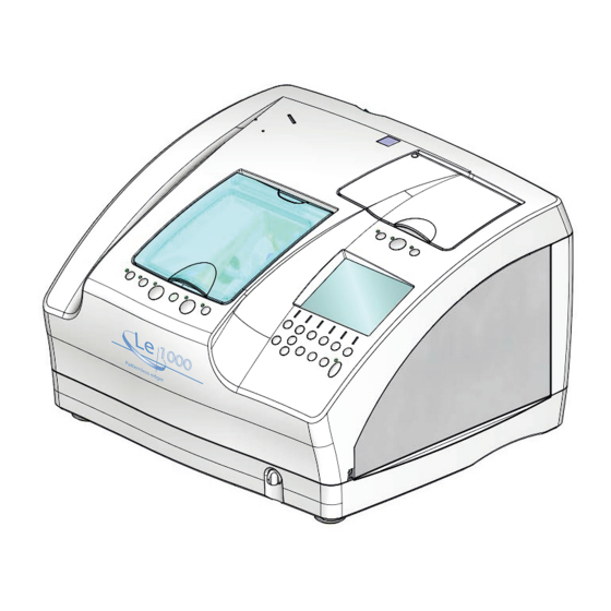
LLE14BRDA001A/E 3.2 Configuration Notch for pattern setting unit Tracing unit lid Processing chamber door Display Flow control Control panel Notch for pattern setting unit The provided pattern setting unitis placed here when not in use. Processing chamber door The door covers the processing chamber. Flow control Controls the flow volume of the cooling water poured over the wheels. - Page 14 LLE14BRDA001A/E Rear view Power switch Vent Outlet for Cooling fan Pump 1 Outlet for Contrast control Pump 2 (CONTRAST) Outlet for Mode switch vacuum control (MODE) RS-232C port (COM2) Inlet Fuse RS-232C port (COM1) Outlet for Pump 1 (Pump 1) Vent Connects with the power cord of the pump Connects to the duct of the deodorizer LED-...
- Page 15 LLE14BRDA001A/E Processing chamber Nozzle for water curtain Feelers (forlens shape measurement) Lens chuck Cup holder Wheels Feedwater Grooving wheel nozzles Safety beveling wheel Cup holder This part holds a lens blocked with a pliable cup. Feedwater nozzles Supply cooling water to the edging area of a lens being processed.
- Page 16 LLE14BRDA001A/E Tracing unit Rim clips Pattern tracing Upper slider Stylus Lower slider Rim clips Pattern setting unit support Upper slider button Lower slider Starts both-eye tracing. Frames are fastened between these sliders. Pattern setting unit support button Mounts the pattern setting unit set with a Starts right-eye tracing.
- Page 17 LLE14BRDA001A/E Control panel-1 button Starts retouching. button Switches safety beveling on or off. button Secures a lens to or releases a lens from the lens chuck. R/L indicator lamp Lights up in green when the right-eye lens is selected and in red when the left-eye lens is selected.
- Page 18 LLE14BRDA001A/E Control panel-2 Frame button Polish button FC button Lens button R/L button cannot be selected in the PLB type.) In button addition, extended pressing of this button switches soft processing on or off. Switches the screen between the layout and menu.
-
Page 19: Model Configuration
LLE14BRDA001A/E 3.3 Model Configuration 3 - 9... -
Page 20: Wheel Configuration
LLE14BRDA001A/E 3.4 Wheel Configuration 69 mm PC (40347-1010) Type Part No. Spacer Finishing wheel for plastic lenses Roughing wheel for glass lenses Roughing wheel for plastic lenses Rotative direction Marking on wheel Rotative direction Part No. 22 mm 17 mm 23 mm 69 mm PLB (40347-1030) -
Page 21: Labels
LLE14BRDA001A/E 3.5 Labels Indicates that caution must be taken. Refer to the operator’s manual before use. Indicates that caution must be taken to avoid cutting fingers. Indicates that the instrument must be supplied only with alternating current. Fuse Indicates that the state of the power switch. When the symbol side of the switch is pressed down, power is supplied to the instrument. - Page 22 LLE14BRDA001A/E (EU area only) 3 - 12...
-
Page 23: Assy. Layout
LLE14BRDA001A/E 3.6 ASSY. Layout 44402 -2100 100V 44402 43401 -21A0 -4000 200V 44401 -5000 40340 -4100 44401 -9300 44001 -5300 44001 44401 -1200 -4000 44001 100V 44401 -9100 44402 44001 -1400 44001 -1000 44001 44001 44001 -12A0 -1600 100V -1100 100V -6000 -5400... -
Page 24: Electrical Component Layout
LLE14BRDA001A/E 3.7 Electrical Component Layout BA07 BA02 CA29 100V 200V BA04 CA26 BA03 100V BA09 200V SYM. PART NO. DESCRIPTION 3 - 14... - Page 25 LLE14BRDA001A/E CA32 CA27 CA31 BA01 BA05 CA17 CA42 CA34 E35a E35b CA28 SYM. PART NO. DESCRIPTION 3 - 15...
- Page 26 LLE14BRDA001A/E CA61 CA63 BA06 CA64 BA11 CA60 BA08 BA13 BA12 CA07 SYM. PART NO. DESCRIPTION 3 - 16...
-
Page 27: Replacement Part List
LLE14BRDA001A 3.8 Replacement Part List : Needs adjustment after replacement : Needs confirmation after replacement 3 - 17... - Page 28 LLE14BRDA001A 3 - 18...
-
Page 29: Troubleshooting
LLE14BRDA001A/E § 4 TROUBLESHOOTING 4 - 1... - Page 30 LLE14BRDA001A/E 4 - 2...
-
Page 31: Removing Procedures
LLE14BRDA001A/E § 5 REMOVING PROCEDURES 5.1 Prior to Removal Work 1. The assembly procedure after replacing parts is generally not described as it is basically the reverse of the disasssembly procedure. However, in exceptional cases, the assembly procedure is specified. 2. -
Page 32: Opening Top Cover Assy
LLE14BRDA001A/E 5.3 Opening Top Cover ASSY. 1. Remove the set screws SB4 × 8 (n = 2) on the top cover ASSY. (44402-2100:100 V or 44402-21A0:200 V). 2. Raise the top cover until the notch of the stay (44401-M245) fits on the rear panel (44401- M169) to lock it. - Page 33 LLE14BRDA001A/E 5. Removing the top cover ASSY. (44402-2100:100 V or 44402-21A0:200 V) Raise the top cover ASSY. (44402-2100:100 V or 44402-21A0:200 V) to release the lock, then slide the ASSY. to the left to release from the hinges [40350-M180 (n = 2)]. 6.
- Page 34 LLE14BRDA001A/E [This page is intentionally left blank.]...
-
Page 35: Replacement Procedures
LLE14BRDA001A/E § 6 REPLACEMENT PROCEDURES Processing adjustment Where there is an indication that readjustment is necessary after part replacement, perform processing adjustment after standard adjustment. See “4.7 Replacement Part List” for the parts which need adjustment. 6.1 Rocker Switch (80460-00123) 80460- Replacement part: Rocker switch (80460-00123) 00123... -
Page 36: Inverter (80607-00027)
LLE14BRDA001A/E 6.3 Inverter (80607-00027) Replacement part: Inverter (80607-00027) 1. Remove the top cover ASSY. (44402-2100) 44402 (100V) 80607- (see 5.4). -2100 00027 2. Disconnect the cable (44401-CA31) from 44402 CK2×5 (200V) -21A0 connector CN1 of the inverter (80607-00027), and disconnect the LCD supplied cable from connector CN2. -
Page 37: Trace Sw Board (44001-Ba02)
LLE14BRDA001A/E 6.5 Trace SW Board (44001-BA02) Replacement part: Trace SW board (44001-BA02) 1. Remove the top cover ASSY. (44402-2100) 44402 (100V) -2100 (see 5.4). BA02 2. Disconnect connector J1 (P501) from the trace 44402 (200V) -21A0 SW board (44001-BA02). 3. Unscrew the P tight screws [40340-M047 (n = 4)] to replace the trace SW board. -
Page 38: Main Sw Board (44401-Ba04)
LLE14BRDA001A/E 6.7 Main SW Board (44401-BA04) Replacement part: Main SW board (44401-BA04) 1. Remove the top cover ASSY. (44402-2100) BA04 (see 5.4). 44402 2. Disconnect connector J1 (P401) from the main (100V) -2100 SW board (44401-BA04). 44402 (200V) 3. Unscrew the P tight screws [40340-M048 (n = -21A0 5)] and spacers [44001-M275 (n = 5)] to remove the main SW board. -
Page 39: Cover Relay Board (44401-Ba07)
LLE14BRDA001A/E 6.8 Cover Relay Board (44401-BA07) Replacement part: Cover relay board (44401-BA07) 1. Remove the top cover ASSY. (44402-2100) 44402 (100V) -2100 (see 5.4). 2. Disconnect all cables from the connector on 44402 (200V) -21A0 the cover relay board (44401-BA07). BA07 3. -
Page 40: Wheels
LLE14BRDA001A/E 6.10 Wheels Replacement part: Wheels Jig: Wheel removal jig (40396-0100) 1. Removing wheels <When the wheel removal jig (40396-0100) is not available> * Wheels may not be removed without the wheel removal jig (40396-0100) when a hexagon bolt is tightened so securely. 1) Open the top cover ASSY. - Page 41 LLE14BRDA001A/E 2. Attaching wheels * For the attachment procedure and configuration of wheels, see “3.4 Wheel Configuration”. 1) Apply the grease (NIPPECO LLP) to the motor shaft. 2) Apply the grease (NIPPECO LLP) to each wheel surface to which the motor shaft contacts. 3) Attach each wheel to the motor shaft seeing “3.4 Wheel Configuration”.
-
Page 42: Grooving Wheel And Safety Bevel Finishing Wheel
LLE14BRDA001A/E 6.11 Grooving Wheel and Safety Bevel Finishing Wheel Replacement part: Grooving wheel (44001-M689), safety bevel wheel (44001-M693) 1. Open the top cover ASSY. (44402-2100) (see 44001 5.3). -6600 2. Unscrew SB3 × 8 (n = 2) to remove the wheel cover (44001-M691). -
Page 43: Tracing Unit Assy. (43401-4000)
LLE14BRDA001A/E 6.13 Tracing unit ASSY. (43401-4000) Replacement part: Tracing unit ASSY. (43401-4000) 1. Remove the top cover ASSY. (44402-2100) CA12 CA33 (see 5.4). 2. Disconnect connectors J2 (P1502) and J7 43401 -4000 (P1507) from the tracing unit board (40340- BA15 BA15). -
Page 44: Feelers
LLE14BRDA001A/E 6.14 Feelers Replacement part: Left feeler (40340-M983), right feeler (40340-M984) * Replace the feelers when the lens-contact surfaces of the left and right feelers obviously wear out and accurate measurement values are not obtained. * Even if the lens-contact surface of each feeler wears out from use, the other surface can be used. -
Page 45: Feeler Assy. (40340-4100)
LLE14BRDA001A/E 6.15 Feeler ASSY. (40340-4100) Replacement part: Feeler ASSY. (40340-4100) 1. Remove the top cover ASSY. (44402-2100) 40340 and left side cover (44401-M208) (see 5.4). -4100 2. Turn manually the arrow-indicating part of the lens measurement unit ASSY. (44001-4000) as shown to the right until the set screws [40340-M291 (n = 2)] of the feeler ASSY. -
Page 46: Lens Measurement Unit Assy. (44401-4000)
LLE14BRDA001A/E 6.16 Lens Measurement Unit ASSY. (44401-4000) Replacement part: Lens measurement unit ASSY. (44401-4000) 1. Remove the top cover ASSY. (44402-2100) and left side cover (44401-M208) (see 5.4). BA06 2. Remove the feeler ASSY. (40340-4100) (see 6.15). 44401 SB6×20 -4000 3. -
Page 47: Pulse Motor (40340-E033)
LLE14BRDA001A/E 6.18 Pulse Motor (40340-E033) Replacement part: Pulse motor (40340-E033) 44401 1. Remove the lens measurement unit ASSY. -4000 (44401-4000) (see 6.16). 2. Disconnect connector J2 (P602) from the board (40340-BA06). 3. Unscrew SB3 × 10 (n = 4) and HH4 × 6 to replace the pulse motor (40340-E033). -
Page 48: Safety Beveling/Grooving Assy. (44001-6000)
LLE14BRDA001A/E 4. Replace the cable (40340-CA33) as follows: 1) Disconnect connector J5 (P605) from the board (40340-BA06). 2) Unscrew CK2 × 5 (n = 2) to replace the cable (40340-CA33). 5. Reassemble the parts in the reverse order. * Readjustment is necessary (see 6.16). 6.21 Safety Beveling/Grooving ASSY. -
Page 49: Pulse Motor (40340-E035)
LLE14BRDA001A/E 6.22 Spindle ASSY. (44001-6600) Replacement part: Spindle ASSY. (44001-6600) 1. Remove the safety beveling/grooving ASSY. 44001 (44001-6000) (see 6.21). -6600 2. Unscrew SB3 × 8 (n = 2) to remove the wheel cover (44001-M691). SB3×8 3. Unscrew SB3 × 8 (n = 2) to replace the spindle ASSY. -
Page 50: Brushless Motor (40347-E054)
LLE14BRDA001A/E 6.25 Brushless Motor (40347-E054) Replacement part: Brushless motor (40347-E054) 1. Remove the top cover ASSY. (44402-2100) and right side cover (44401-M209) (see 5.4). 44401 2. Raise the carriage ASSY. (44001-5000) by -5000 hand in the direction of arrow as shown to the (100V) right. -
Page 51: Guide (44401-M931)
LLE14BRDA001A/E 6.26 Guide (44401-M931) Replacement part: Guide (44001-M931) 1. Open the top cover ASSY. (44402-2100) (see 5.3). 2. Disconnect connector CN07 of the LED cable (44001-CA50). 3. Peel off the protective sheet (44001-M905). 4. Replace the guide (44001-M931). 6.27 Processing Chamber ASSY. (44401-9300) Replacement part: Processing chamber ASSY. -
Page 52: Lower Processing Chamber Assy. (44001-9100)
LLE14BRDA001A/E 6. Loosen HH4 × 4 (n = 4). SB4×10 7. Unscrew SB4 × 10 to replace the processing chamber ASSY. (44401-9300). 8. Reassemble the parts in the reverse order. 44401 1) Perform the arm position adjustment -9300 and calibration of the safety beveling/ grooving ASSY. -
Page 53: Carriage Assy. (44401-5000)
LLE14BRDA001A/E 6.29 Carriage ASSY. (44401-5000) Replacement part: Carriage ASSY. (44401-5000) 1. Remove the top cover ASSY. (44402-2100), left side cover (44401-M208), and right side cover (44401-M209) (see 5.4). 2. Remove the guide (44001-M931) (see 6.27). 3. Remove the feeler ASSY. (40340-4100) (see 6.15). 4. -
Page 54: Y Axis Motor Assy. (44001-5400)
LLE14BRDA001A/E 8. Remove the carriage ASSY. (44401-5000) (see 6.30). 9. Disconnect connector CN06 of the DC motor (44001-E042) and connector J3 (P503) of the carriage relay board (44401-BA05). 44001 10. Unscrew SB6 × 40 (n = 2) to replace the chuck -5300 axis motor ASSY. -
Page 55: Dc Motor (44001-E042)
LLE14BRDA001A/E 3. Unscrew HH4 × 3 (n = 2) and SB3 × 8 (n = 4) to replace the stepping motor (44001-E035). 4. Reassemble the parts in the reverse order. 1) Perform the calibration of the safety beveling/grooving ASSY. (see 7.5.3). 2) Perform the calibration of the lens measurement unit ASSY. -
Page 56: Carriage Relay Board (44401-Ba05)
LLE14BRDA001A/E 6.33 Carriage Relay Board (44401-BA05) Replacement part: Carriage relay board (44401-BA05) 1. Remove the top cover ASSY. (44402-2100), left side cover (44401-M209), and right side cover (44401-M209) (see 5.4). 2. Disconnect connector J1 (P501) of the carriage relay board (44401-BA05). 3. -
Page 57: Pulse Motor (44001-E037), Sensor Cable (44001-Ca17)
LLE14BRDA001A/E 6.35.1 X axis motor ASSY. (44001-1100) Replacement part: X axis motor ASSY. (44001-1100) 1. Remove the top cover ASSY. (44402-2100), 44001 left side cover (44401-M208), and right side -1100 cover (44401-M209) (see 5.4). SB6×15 2. Disconnect connectors J9 (P109) and J10 (P110) on the main board (44401-BA01). -
Page 58: Feedwater Assy. (44001-1600)
LLE14BRDA001A/E 6.36 Feedwater ASSY. (44001-1600) Replacement part: Feedwater ASSY. (44001-1600) 1. Remove the top cover ASSY. (44402-2100) and right side cover (44401-M209) (see 5.4). 2. Remove the motor ASSY. (40347-1400) (see 6.26). 3. Remove the tubes (44001-M080, M081) from the elbow (41274-M262). 4. -
Page 59: Dc Fan (40350-E016)
LLE14BRDA001A/E 6.38 DC Fan (40350-E016) Replacement part: DC fan (40350-E016) 1. Remove the top coverASSY. (44402-2100) and rear cover (44001-M203) (see 5.4). 2. Disconnect connector CN08 of the DC fan (40350-E016). 3. Unscrew PC4 × 30 (n = 4) to remove the DC fan (40350-E016). -
Page 60: Fuse Holder (80401-00038)
LLE14BRDA001A/E 6.41 Fuse Holder (80401-00038) Replacement part: Fuse holder (80401-00038) 1. Remove the top cover ASSY. (44402-2100) Supplied nuts and rear cover (44001-M203) (see 5.4). 2. Remove the tracing unit ASSY. (43401-4000) (see 6.13). 3. Disconnect all cables from the fuse holders [80401-00038 (n = 2)]. -
Page 61: Reactor (40350-E043)
LLE14BRDA001A/E 6.43 Reactor (40350-E043) Replacement part: Reactor (40350-E043) 1. Remove the top cover ASSY. (44402-2100), rear cover (44001-M203), and right side cover (44401-M209) (see 5.4). 2. Remove the tracing unit ASSY. (43401-4000) SPC4×6 (see 6.13). 3. Disconnect connector DC BUS (PD/P) from the inverter for the BL motor (40340-E066 for 100 V or 40340-E067 for 200 V). -
Page 62: Mains Part Assy. (44401-1200, 12A0)
LLE14BRDA001A/E 6.45 Mains Part ASSY. (44401-1200, 12A0) Replacement part: Mains part ASSY. (44401-1200 for 100 V or 44401-12A0 for 200 V) 1. Remove the top cover ASSY. (44402-2100), rear cover (44001-M203), left side cover 100V 230V BA01 (44401-M208), and right side cover (44401- 44401 44401 M209) (see 5.4). -
Page 63: Switching Regulator (80602-00107)
LLE14BRDA001A/E 6.47 Switching Regulator (80602-00107) Replacement part: Switching regulator (80602-00107) 1. Remove the top cover ASSY. (44402-2100), AS4×10 rear cover (44001-M203), left side cover 80602- 00107 (44401-M208), and right side cover (44401- M209) (see 5.4). 2. Remove the mains part ASSY. (44401-1200 for 100 V or 44401-12A0 for 200 V) (see 6.47). -
Page 64: Line Noise Filter (80404-00043)
LLE14BRDA001A/E 6.50 Line Noise Filter (80404-00043) Replacement part: Line noise filter (80404-00043) 1. Remove the top cover ASSY. (44402-2100), rear cover (44001-M203), left side cover (44401-M208), and right side cover (44401- M209) (see 5.4). 2. Remove the mains part ASSY. (44401-1200 for 100 V or 44401-12A0 for 200 V) (see 6.47). -
Page 65: Setting/Adjustment
LLE14BRDA001A/E § 7 SETTING/ADJUSTMENT 7.1 Notes for Proper Settings and Adjustments 1. Prepare jigs necessary for adjustment and measurement (see 8.7). 2. See “TROUBLESHOOTING” or use the Lex 1000 φ45 or 45 internal data to determine from which the trouble results, the tracing unit or processing chamber. 3.When the trouble results from the p r o c e s s i n g c h a m b e r ,... -
Page 66: Utility Program
Power switch (COM1) cable for Master to the PC COM1 port. 2. Turn off the Le 1000. Connect the other end of the cross cable to the RS-232C connector. 3. Open the top cover ASSY. (see 5.3). 4. Slide the protection switch (SW1) on the main board (44401-BA01) to the ON side to release the write protection. -
Page 67: Eeprom Initialization
LLE14BRDA001A/E 7.2.2 EEPROM initialization Purpose: Select “SYSTEM SETTING MODE” → “EEPROM INITIALIZE” to initialize the EEPROM (approx. 3 seconds). 1. Turn on the Le 1000. 2. Press while pressing to display the SYSTEM SETTING MODE screen. 3. Press to align the arrow (→) to EEPROM INITIALIZE, then press The EEPROM INITIALIZE screen appears. -
Page 68: Writing Program To Tracing Unit Cpu
ON position (lower side) to release the write protection. 5. Turn on the Le 1000. Although the Le 1000 main body is initialized, the tracing unit is not. If the protect switch is not released in Step 4, the tracing unit starts the normal operation. -
Page 69: Parameter Settings
LLE14BRDA001A/E 7.2.4 Parameter settings 7.2.4.1 Displaying PARAMETER SETTING screen 1. Turn on the power of the main body. 2. Press while pressing The SYSTEM SETTING MODE screen appears. t o m o v e t h e a r r o w ( →) t o 3. -
Page 70: Displaying Wheel Parameter Screen
LLE14BRDA001A/E 7.2.4.2 Displaying WHEEL PARAMETER screen 1. Turn on the power of the main body. 2. Press while pressing The SYSTEM SETTING MODE screen appears. 3. Press to move the arrow (→) to WHEEL PARAMETER, then press The WHEEL PARAMETER screen appears. 4. -
Page 71: Parameter List
LLE14BRDA001A/E 7.2.4.3 Parameter list SYSTEM SETTING MODE PLB-G PLB2R SYSTEM MODE Groove & SFB UNIT None None Exec 0032 65535 SERVER No. 00001 65535 ID No. INPUT DEVICE BarCord BarCode Tenkey SYSTEM PARAMETER SETTING 0.50 0.25 0.50 FPD Step Polish Rotation (PLA) 0002 0001 0015... - Page 72 LLE14BRDA001A/E Parameter Setting range Default MENU SIZE ADJUSTMENT Finish size(PLA,bevel) 0.00 -9.99 +9.99 0.00 -9.99 +9.99 Finish size(PLA,flat) Finish size(PC,bevel) 0.00 -9.99 +9.99 0.00 -9.99 +9.99 Finish size(PC,flat) Finish size(GLS,bevel) 0.00 -9.99 +9.99 0.00 -9.99 +9.99 Finish size(GLS,flat) Finish size(HPL,bevel) 0.00 -9.99 +9.99...
- Page 73 LLE14BRDA001A/E Parameter Setting range Default PD ADJUSTMENT 0.00 -1.00 +1.00 PD constant +5.0 +30.0 Frame tilt angle(FLT) GROOVING/SAFETY BEVELING ADJUSTMENT Groove Depth Groove Width 0.00 -9.99 +9.99 Groove Position Safety Bevel Mode F&R SFB Wheel Height +0.2 +1.0 SFB Width(BVL,Front) +0.3 +1.0 +0.2...
-
Page 74: Hardware Test Program
LLE14BRDA001A/E 7.2.5 HARDWARE TEST program Purpose: Specifying the malfunction or maladjustment spot with “HARDWARE TEST” when the trouble results from the processing chamber. 1. Turn on the main body. 2. Press while pressing to display the SYSTEM SETTING MODE screen. 3. - Page 75 LLE14BRDA001A/E 7. “θ Axis” 1) Displays the θ axis origin sensor between ON/OFF. (ON/OFF is adjusted with [CW] and [CCW].) 8. “CHUCK” 1) Displays the chuck OPEN/CLOSE sensor. 2) Pressing [Open] opens the chuck axis. 3) Pressing [Close] closes the chuck axis. 9.
- Page 76 LLE14BRDA001A/E 10. “LMU” 1) Displays the LMU ASSY. origin sensor between ON and OFF. 2) Pressing [Init] sets the LMU ASSY. in the standby position. Pressing [Down] sets the LMU ASSY. in the measurement position. 3) Displays the output value of the LMU ASSY.
-
Page 77: Mechanical Components
LLE14BRDA001A/E 7.3 Mechanical Components 7.3.1 Carriage ASSY. (44401-5000) 7.3.1.1 Rattle removal of carriage ASSY. bearing Purpose: Rattle adjustment of the carriage ASSY. bearing (40340-M556) 1. Open the top cover ASSY. (44402-2100) to remove the left side cover (44401-M208) and 44401 -5000 right side cover (44401-M209) (see 5.3 and 5.4). -
Page 78: Engagement Of X Axis Motor Assy. Motor Gear
LLE14BRDA001A/E 7.3.1.2 Engagement of X axis motor ASSY. motor gear Purpose: Adjusting the engagement of the motor gear in the X axis motor ASSY. (44001- 1100) 1. Open the top cover ASSY. (44402-2100) to remove the left side cover (44401-M208) and right side cover (44401-M209) (see 5.3 and 44401 5.4). -
Page 79: Height Of Carriage Assy. Y Axis
LLE14BRDA001A/E 7.3.1.3 Height of carriage ASSY. Y axis Purpose: Peforming adjustment and calibration of the carriage ASSY. Y axis height with the Y axis adjustment jig Jig: Y axis adjustment jig LEDJ-16(40396-M002) Note: Perform this adjustment along with that of θ axis of the carriage ASSY. Y axis (see 7.3.1.4) in order to insert the pin (44001-M551) into the notch of the Y axis adjustment jig (40396-M002). -
Page 80: Θ Axis Of Carriage Assy. Y Axis
LLE14BRDA001A/E 7.3.1.4 q axis of carriage ASSY. Y axis Purpose: Performing adjustment and calibration of the θ axis of the carriage ASSY. Y axis using the Y axis adjustment jig Jig: Y axis adjustment jig LEDJ-16 (40396-M002) Note: Perform this adjustment along with that of the carriage ASSY. Y axis height (see 7.3.1.3) in order to insert the pin (44001-M551) into the notch of the Y axis adjustment jig (40396-M002). -
Page 81: Position Of Carriage Assy. Left/Right Shaft
LLE14BRDA001A/E 7.3.1.5 Position of carriage ASSY. left/right shaft Purpose: Performing position adjustment and calibration of the left/right shaft using the left/ right shaft adjustment jig after adjusting the height and θ axis of the carriage ASSY. Y axis. Jig: Left/right shaft adjustment jig LEDJ-16(40396-M001) 1. -
Page 82: Lens Measurement Unit Assy
LLE14BRDA001A/E 7.3.2 Lens measurement unit ASSY. 7.3.2.1 Feeler ASSY. height Purpose: Adjusting the height of the feeler ASSY. (40340-4100) 40340 Jig: Calibration jig LEDJ-16 (40396-M011) -4100 1. Turn on the power switch. 3PW4 44401 2. Open the top cover ASSY. (44402-2100) (see -4000 5.3). -
Page 83: Initial Position Of Feeler Assy
LLE14BRDA001A/E 7.3.2.2 Initial position of feeler ASSY. Purpose: Adjusting the initial position of the feeler ASSY.(40340-4100) 1. Open the top cover ASSY. (44402-2100) (see CA31 HH4×6 Roller 5.3). 2. Turn the crank (40340-M272) until the feeler Notch ASSY. (40340-4100) flips up and the crank cannot be turned. - Page 84 LLE14BRDA001A/E 6. Adjust the attachment position of the shading plate (40340-M249) so that the multimeter reads 0.7 to 0.9 V. SB4×10 7. Loosen SB4 × 10 (n = 2) fixing the cover support (40340-M290). With the cover ASSY. closed, press the cover support against the cover ASSY.
-
Page 85: Safety Beveling/Grooving Assy. (44001-6000)
LLE14BRDA001A/E 7.3.3 Safety beveling/grooving ASSY. (44001-6000) 7.3.3.1 Position of safety beveling/grooving ASSY. arm Purpose: Adjusting the position of the arm (spindle ASSY. ) in the safety beveling/grooving ASSY. (44001-6000) Jig: SFB adjustment jig LEDJ-16(40396-M003) 44001 -6600 1. Open the top cover ASSY. (44402-2100) (see 5.3). -
Page 86: Chuck Pressure
LLE14BRDA001A/E 7.3.4 Chuck pressure 7.3.4.1 Tentative chuck pressure Purpose: Adjusting tentative chuck pressure using the chuck pressure measurement jig Jig: Chuck pressure measurement jig LEDJ-11(40391-0100) 1. Open the top cover ASSY. (44402-2100) to remove the right side cover (44401-M209) (see 5.3 and 5.4). 2. -
Page 87: Chuck Pressure
LLE14BRDA001A/E 7.3.4.2 Chuck pressure Purpose: Adjusting chuck pressure on the SYSTEM PARAMETER SETTING screen using the chuck pressure measurement jig Jig: Chuck pressure measurement jig LEDJ-11(40391-0100) 1. Display the SYSTEM SETTING MODE screen (see 7.2.2). 2. Press to select “SYSTEM PARAMETER SETTING”, then press 3. -
Page 88: Tracing Unit (43401-4000)
LLE14BRDA001A/E 7.3.5 Tracing unit (43401-4000) 7.3.5.1 Tilt of tracing unit stylus Purpose: Adjusting the tilt of the tracing unit stylus (40340-M474) Jig: Standard frame (40340-M391) 1.Set the standard frame (40340-M391) to the tracing unit. 2. Press and hold (both-eye tracing) for approx. -
Page 89: Cleaning Of Pattern Tracing Pin
LLE14BRDA001A/E 7.3.5.3 Cleaning of pattern tracing pin Purpose: Cleaning the pattern tracing pin (40340-M824) Jig: Lint-free wiper, mixed-alcohol solution Slider 1. Turn on the power. 2. Open fully the sliders of the tracing unit, hold them by hand, and press 3. -
Page 90: Electrical Components
LLE14BRDA001A/E 7.4 Electrical Components 7.4.1 Parameters of BL motor inverter Purpose: Setting the parameters of the inverter for the BL motor (40340-E066 for 100 V or 40340-E067 for 200 V) with the control panel 1. Remove the top cover ASSY. (44402-2100), rear cover (44001-M203), left side cover (44401- M208), and right side cover (44401-M209) (see 5.4). -
Page 91: Parameter List Of Bl Motor (40340-E066,E067) Inverter
LLE14BRDA001A/E 7.4.2 Parameter list of BL motor (40340-E066,E067) inverter User parameter 7 - 27... - Page 92 LLE14BRDA001A/E User parameter 7 - 28...
- Page 93 LLE14BRDA001A/E System parameter 7 - 29...
-
Page 94: Trip Table Of Bl Motor Inverter
LLE14BRDA001A/E 7.4.3 Trip table of BL motor inverter Monitor When the output current reaches the electron thermal level and the Electron thermal operation (blink) timer starts, the indication on the monitor will blink. When the direct voltage becomes approx. DC 200 V or less for AC 200 V , or the direct voltage becomes approx. -
Page 95: Calibration
LLE14BRDA001A/E 7.5 Calibration 7.5.1 Displaying calibration screen 1. Turn on the main body. 2. Press while pressing to display the SYSTEM SETTING MODE screen. t o m o v e t h e a r r o w ( →) t o 3. -
Page 96: Calibration Of Safety Beveling/Grooving Assy
LLE14BRDA001A/E 7.5.3 Calibration of safety beveling/grooving ASSY. Purpose: Performing calibration of the safety beveling/grooving ASSY. (44001-6000) (approx. 4 minutes) Jig: SFB adjustment jig LEDJ-16 (40396-M003), Calibration jig LEDJ-16 (40396-M011) 1. Adjust the position of the arm in the safety beveling/grooving ASSY. (see 7.3.3.1). SFB arm 2. -
Page 97: Wheel Calibration
LLE14BRDA001A/E 7.5.4 Wheel calibration Purpose: Performing wheel calibration (approx. 2 minutes) Jig: Calibration jig LEDJ-16 (40396-M011) 1. Display the SYSTEM SETTING MODE screen → CALIBRATION screen (see 7.5.1). 2. Attach the calibration jig (40396-M011) (see 7.5.2). 3. Pressing starts WHEEL CALIBRATION. 4. -
Page 98: Calibration Of Lens Measurement Unit Assy
LLE14BRDA001A/E 7.5.5 Calibration of lens measurement unit ASSY. Purpose: Performing calibration of the lens measurement unit ASSY. (44401-4000) (approx. 1 minute) Jig: Calibration jig LEDJ-16 (40396-M011) 1. Display the SYSTEM SETTING MODE screen → CALIBRATION screen (see 7.5.1). 2. Attach the calibration jig (40396-M011) (see 7.5.2). -
Page 99: Torque Calibration Of Tracing Unit
LLE14BRDA001A/E 7.5.6 Torque calibration of tracing unit Purpose: Performing torque calibration of the tracing unit 1. While pressing simultaneously, turn on the power. 2. After confirming the LED of blinks, open fully the sliders of the tracing unit by hand. 3. -
Page 100: Full Calibration Of Tracing Unit
LLE14BRDA001A/E 3. After confirming the LED of blinks, press * After the auto calibration is properly completed, a short beep sounds. If continuing beeps sound, the calibration is not completed properly. The measurement data may be outside the tolerance. It is necessary to inspect the inside of the tracing unit. 7.5.9 Full calibration of tracing unit Purpose: Performing full calibraion of the tracing unit using the 45 standard pattern jig,... - Page 101 LLE14BRDA001A/E 8. After measurement is completed, confirm that (40390-3300) blinks. Then set the φ60 the LED of standard frame jig (40390-3300) as shown to the right. * Set the jig in the maximum possible center since the frame gain adjustment can be affected.
-
Page 102: Processing Adjustment
LLE14BRDA001A/E 7.6 Processing Adjustment 7.6.1 Feeler axis Purpose: Adjusting the front and rear feeler axes Jig: Axis alignment jig 1. Turn on the main body. 2. Press while pressing to display the SYSTEM SETTING MODE screen. t o m o v e t h e a r r o w ( →) t o 3. - Page 103 LLE14BRDA001A/E <When using the axis alignment jig> 1. Adjust the rear feeler axis as follows: 1) Prepare a flat lens and apply powder or grease only to its rear surface. 2) Call up the 45 internal data. 3) Set the lens and press in flat edging.
- Page 104 LLE14BRDA001A/E <When using the 45 internal data> 1) Call up the 45 internal data. 2) Set the size to +3.00 and flat edge a lens. 3) Apply powder or grease to the rear surface of the processed lens. Set the size to 0.00 and press 4) After the rear surface measurement is completed, press 5) Confirm that the measurement trace on the rear surface is parallel to the lens edges.
-
Page 105: Finish Size
LLE14BRDA001A/E 7.6.2 Finish size Purpose: Adjusting finish size of a lens processed with the φ45 internal data Jig: For adjustment of CR39 finish size, a lens of -3 to -5 D is recommended. 1. Turn on the main body and press display the MENU screen. -
Page 106: Lens Axis
LLE14BRDA001A/E 3. Call up the φ45 internal data. 4. Guided bevel the lens (5:5) and check the bevel position. 5. If the bevel position is not in the center of the lens edge when visually checked, move the arrow (→) to “Bevel adjustment” and press to change the parameter value. - Page 107 LLE14BRDA001A/E <When using the axis alignment jig> 1) Call up the 45 internal data. 2) Set the processed lens to the axis alignment jig and measure the axis angle based on the lens top edge and jig horizontal lines. 3) If the axis is misaligned, adjust it by changing the parameter value. 4) Check the axis with the lens set to the axis alignment jig.
-
Page 108: Polish (Differential, Polishing Wheel Height, Bevel, Axis)
LLE14BRDA001A/E 7.6.5 Polish (differential, polishing wheel height, bevel, axis) Purpose: Adjusting polish (differential, polishing wheel height, bevel, axis) of a lens processed with the φ45 or 45 internal data Jig: For adjusting CR39 polish size, a lens of -3 to -5 D is recommended. 7.6.5.1 Polish (differential, polishing wheel height) <When checking a lens flat edged with PLB>... -
Page 109: Bevel Position To Be Polished
LLE14BRDA001A/E 3) Press to move the arrow (→) to “Polish wheel size”. Press to adjust the numeric value. • Decreasing the value moves the lens close to the wheel. • Increasing the value moves the lens away from the wheel. 8. - Page 110 LLE14BRDA001A/E 2) Press to move the arrow (→) to “Bevel adjustment” and press . The Bevel adjustment screen appears. 3) Press to move the arrow (→) to “Polish bevel const.”. Press to adjust the numeric value. • Increasing the value moves the bevel position to be polished to the lens front side. •...
-
Page 111: Flat Polish Axis
LLE14BRDA001A/E 7.6.5.3 Flat polish axis 1. Turn on the main body and press to display the MENU screen. 2. Press to move the arrow (→) to “Size adjustment”, then press The Size adjustment screen appears. 3. Press to move the arrow (→) to “Polish level (PLA, flat)”. Press to set the value to “0.00”. -
Page 112: Bevel Polish Axis
LLE14BRDA001A/E 7.6.5.4 Bevel polish axis 1. Turn on the main body and press to display the MENU screen. 2. Press to move the arrow (→) to “Size adjustment”, then press The Size adjustment screen appears. 3. Press to move the arrow (→) to “Polish level (PLA, bevel)”, then press to set the value to “0.00”. -
Page 113: Polycarbonate Polish Differential
LLE14BRDA001A/E 7.6.5.5 Polycarbonate polish differential Purpose: Adjusting polish differential of a polycarbonate lens processed with the φ45 internal data Jig: For adjusting CR39 polish differential, a lens of -3 to -5 D is recommended. 1. Turn on the main body and press display the MENU screen. -
Page 114: Groove
LLE14BRDA001A/E 7.6.6 Groove 7.6.6.1 Groove depth Purpose: Adjusting groove depth of a lens processed with the φ45 internal data Jig: For adjusting CR39 groove depth, a lens of -3 to -5 D is recommended. 1. Turn on the main body and press display the MENU screen. -
Page 115: Groove Position
LLE14BRDA001A/E 7.6.6.2 Groove position Purpose: Adjusting groove position of a lens processed with the φ45 internal data Jig: For adjusting CR39 groove position, a lens of -3 to -5 D is recommended. 1. Turn on the main body and press display the MENU screen. -
Page 116: Groove Axis
LLE14BRDA001A/E 7.6.6.3 Groove axis Purpose: Adjusting groove axis of a lens processed with the 45 internal data * When the groove depth is not uniform even after the groove depth adjustment is performed, perform the groove axis adjustment. Jig: For adjusting CR39 groove axis, a lens of -3 to -5 D is recommended. 1. -
Page 117: Safety Bevel
LLE14BRDA001A/E 7.6.7 Safety bevel Purpose: Adjusting the positions of the beveling/safety beveling wheel and flat edging/safety beveling wheel for a lens processed with the φ45 internal data Jig: For adjusting CR39 safety bevel, a lens of -3 to -5 D is recommended. 1. -
Page 118: Bevel/Safety Bevel Axis
LLE14BRDA001A/E <Flat edging/safety beveling wheel position adjustment> 1) Call up the φ45 internal data. 2) Select MTL and GUI (5:5). Flat edge and safety bevel a CR39, -3 to -5 D lens. 3) Press to move the arrow (→) to “SFB Wheel Pos. -
Page 119: Flat Edge/Safety Bevel Axis
LLE14BRDA001A/E • When the safety bevel width on the right side of the top edge is wider, decrease the value. • When the safety bevel width on the left side of the top edge is wider, increase the value. Front surface 6. - Page 120 LLE14BRDA001A/E 3. Call up the 45 internal data. 4. Select GUI (5:5). Bevel and safety bevel a CR39, -3 to -5 D lens. 5. Check the safety bevel axis on the front surface.• Confirm that the safety bevel width remains nearly the same along the top edge from left to right as seen from the lens front.
-
Page 121: Other Settings And Adjustments
LLE14BRDA001A/E 7.7 Other Settings and Adjustments 7.7.1 Dressing wheels Purpose: If wheels are dull, the processing time becomes longer or the accuracy in size and polish becomes low. Dress wheels periodically. Jig: Dressing stick for roughing wheel (orange) WA80K, dressing stick for finishing wheel (white) WA320K, compound kit (40380-1700) 1. - Page 122 LLE14BRDA001A/E 4. Open the processing chamber door. 5. Dress the wheel. <Roughing wheel for glass lenses and finishing wheel> 1) Press . The wheel rotates and cooling water runs. 2) Wet the dressing stick well with running water. Finishing wheel => Use the dressing stick for finishing wheel. Roughing wheel for glass lenses =>...
- Page 123 LLE14BRDA001A/E 6) Holding the stick by its handle, lightly touch the compound covered pad surface to the rotating polishing wheel. The pad is gradually worn away. Dress the wheel until the white surface of the pad wears away. Be careful not to let the pad wear away all the way to the stick.
- Page 124 LLE14BRDA001A/E <Grooving wheel> 1) Press . The safety beveling wheel Dressing ASSY. comes out and the cooling water stick runs. 2) Wet the dressing stick for finishing wheel well with running water. 3) Press to stop the cooling water. 4) Lightly touch the dressing stick to the grooving wheel from directly above until the dressing stick is slightly grooved.
-
Page 125: Supplement
LLE14BRDA001A/E § 8 SUPPLEMENT 8.1 Wiring Diagram 80460-00123 80404-00043 80602-00107 80401-00038 80457-00085 8 - 1... -
Page 126: Connector Cable
LLE14BRDA001A/E 8.2 Connector Cable 8 - 2... - Page 127 LLE14BRDA001A/E 8 - 3...
- Page 128 LLE14BRDA001A/E 8 - 4...
- Page 129 LLE14BRDA001A/E 8 - 5...
- Page 130 LLE14BRDA001A/E 8 - 6...
-
Page 131: Main Board (44401-Ba01)
LLE14BRDA001A/E 44401-BA01 44401-BA01 MAIN BOARD 8 - 7... -
Page 132: Grease
LLE14BRDA001A/E 8.4 Grease 44401-1400 (100 V) 44401-14A0 (200 V) (100V) (200V) Grease (NBU15) 44001-6000 CA34 Grease (NBU15) 44001-6600 Grease (NBU15) 8 - 8... - Page 133 LLE14BRDA001A/E 44401-5000 Grease Grease (NIPPECO LLP) 82011- 82001- (NIPPECO LLP) 2537C SL030 Grease 522b (NIPPECO LLP) Grease 527c (NIPPECO LLP) Grease (SHV-2) 82011- 1532C 527b 527a 522a 82012- 0612A 82012- 0612A 82012- 0612A 82011- 0613A Grease (SHV-2) 82018- 82011- A030C 82011- 0613A 2537C...
-
Page 134: Grease Msds
LLE14BRDA001A/E 8.5 Grease MSDS 8.5.1 NIPPECO LLP 8 - 10... - Page 135 LLE14BRDA001A/E 8 - 11...
-
Page 136: Be-4
LLE14BRDA001A/E 8.5.2 BE-4 8 - 12... - Page 137 LLE14BRDA001A/E 8 - 13...
-
Page 138: Shv-2
LLE14BRDA001A/E 8.5.3 SHV-2 8 - 14... - Page 139 LLE14BRDA001A/E 8 - 15...
-
Page 140: Nbu15
LLE14BRDA001A/E 8.5.4 NBU15 8 - 16... - Page 141 LLE14BRDA001A/E 8 - 17...
- Page 142 LLE14BRDA001A/E 8 - 18...
- Page 143 LLE14BRDA001A/E 8 - 19...
- Page 144 LLE14BRDA001A/E 8 - 20...
-
Page 145: Troubles And Measures
LLE14BRDA001A/E 8.6 Troubles and Measures 8 - 21... - Page 146 LLE14BRDA001A/E 8 - 22...
- Page 147 LLE14BRDA001A/E 8 - 23...
- Page 148 LLE14BRDA001A/E 8 - 24...
- Page 149 LLE14BRDA001A/E 8 - 25...
-
Page 150: Jigs
LLE14BRDA001A/E 8.7 Jigs Long offset wrench (40390-M603) 45 standard pattern (41476-M002) φ30 standard frame (40390-3100) Left/right shaft rotation adjustment jig (40396-M001) Y axis adjustment jig (40396-M002) φ60 standard frame (40390-3300) SFB adjustment jig (40396-M003) Wheel remover (40396-0100) Calibration jig (40396-M011) Chuck pressure measurement jig (40391-0100) 45 standard pattern (40390-M301) -
Page 151: Tools
LLE14BRDA001A/E 8.8 Tools Article name Model Manufacturer • Phillips screwdriver D30 0-100 Hozan D30 1-100 Hozan D30 2-100 Hozan • Phillips screwdriver with magnet No. 6300 2×200 Vessel • Stubby Phillips style screwdriver D65P No. 2 2653 Hozan • Precision Phillips screwdriver set DK-20 Futaba kogu •... - Page 152 LLE14BRDA001A/E [This page is intentionally left blank.] 8 - 28...
Need help?
Do you have a question about the Le 1000 and is the answer not in the manual?
Questions and answers