Sign In
Upload
Manuals
Brands
Nidek Medical Manuals
Edger
Le 1000
Nidek Medical Le 1000 Manuals
Manuals and User Guides for Nidek Medical Le 1000. We have
1
Nidek Medical Le 1000 manual available for free PDF download: Service Manual
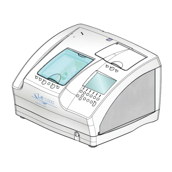
Nidek Medical Le 1000 Service Manual (152 pages)
Brand:
Nidek Medical
| Category:
Edger
| Size: 37 MB
Table of Contents
Table of Contents
3
Introduction
7
Safety Precautions
9
Product Outline
11
Quality Standard
11
Configuration
13
Model Configuration
19
Wheel Configuration
20
Labels
21
ASSY. Layout
23
Electrical Component Layout
24
Replacement Part List
27
Troubleshooting
29
Removing Procedures
31
Prior to Removal Work
31
Abbreviations for Screws
31
Opening Top Cover ASSY
32
Removing Covers
32
Replacement Procedures
35
Rocker Switch (80460-00123)
35
Main Board (44401-BA01)
35
Inverter (80607-00027)
36
Monochrome LCD (80607-00025)
36
Trace SW Board (44001-BA02)
37
Setting SW Board (44401-BA03)
37
Main SW Board (44401-BA04)
38
Cover Relay Board (44401-BA07)
39
Sensor Cable (44401-CA37)
39
Wheels
40
Grooving Wheel and Safety Bevel Finishing Wheel
42
Stylus (40340-M474)
42
Tracing Unit ASSY. (43401-4000)
43
Feelers
44
Feeler ASSY. (40340-4100)
45
Lens Measurement Unit ASSY. (44401-4000)
46
Lens Measurement Board (40340-BA06)
46
Pulse Motor (40340-E033)
47
Encoder (40340-E043)
47
Cables (40340-CA31, CA32, CA33)
47
Safety Beveling/Grooving ASSY. (44001-6000)
48
Pulse Motor (40340-E035)
49
Sensor Cable (44001-CA42)
49
Spindle ASSY. (44001-6600)
49
Brushless Motor (40347-E054)
50
Guide (44401-M931)
51
Processing Chamber ASSY. (44401-9300)
51
Lower Processing Chamber ASSY. (44001-9100)
52
Carriage ASSY. (44401-5000)
53
Chuck Axis Motor ASSY. (44001-5300)
53
Y Axis Motor ASSY. (44001-5400)
54
Y Axis Stepping Motor (44001-E035)
54
DC Motor (44001-E042)
55
Axis Stepping Motor (44401-E022)
55
Carriage Relay Board (44401-BA05)
56
Sensor Cables (44001-CA27, CA29)
56
Sensor Cables (44001-CA26, CA28)
56
Pulse Motor (44001-E037), Sensor Cable (44001-CA17)
57
X Axis Motor ASSY. (44001-1100)
57
Feedwater ASSY. (44001-1600)
58
DC Fan (40350-E016)
59
Communication Connector Board (44401-BA08)
59
Cables CA07 (44001-CA07)
59
Fuse Holder (80401-00038)
60
Inlet (80457-00085)
60
Reactor (40350-E043)
61
Regenerative Resistor for BL Motor (40340-E069)
61
Mains Part ASSY. (44401-1200, 12A0)
62
Inverter for BL Motor (40340-E066, E067)
62
Switching Regulator (80602-00107)
63
Motor Driver (44001-E036)
63
SSR Board (44001-BA09)
63
Line Noise Filter (80404-00043)
64
Setting/Adjustment
65
Notes for Proper Settings and Adjustments
65
Utility Program
66
Writing Program to Master CPU
66
EEPROM Initialization
67
Writing Program to Tracing Unit CPU
68
Parameter Settings
69
Displaying PARAMETER SETTING Screen
69
Displaying WHEEL PARAMETER Screen
70
Parameter List
71
HARDWARE TEST Program
74
Mechanical Components
77
Rattle Removal of Carriage ASSY. Bearing
77
Engagement of X Axis Motor ASSY. Motor Gear
78
Height of Carriage ASSY. y Axis
79
Θ Axis of Carriage ASSY. y Axis
80
Position of Carriage ASSY. Left/Right Shaft
81
Lens Measurement Unit ASSY
82
Feeler ASSY. Height
82
Initial Position of Feeler ASSY
83
Voltage of Lens Measurement Unit ASSY
83
Safety Beveling/Grooving ASSY. (44001-6000)
85
Position of Safety Beveling/Grooving ASSY. Arm
85
Chuck Pressure
86
Tentative Chuck Pressure
86
Chuck Pressure
87
Tracing Unit (43401-4000)
88
Tilt of Tracing Unit Stylus
88
Position of Cable CA63
88
Cleaning of Pattern Tracing Pin
89
Electrical Components
90
Parameters BL Motor Inverter
90
Parameter List of BL Motor (40340-E066,E067) Inverter
91
Trip Table of BL Motor Inverter
94
Calibration
95
Displaying Calibration Screen
95
Attaching Calibration Jig
95
Calibration of Safety Beveling/Grooving ASSY
96
Wheel Calibration
97
Calibration of Lens Measurement Unit ASSY
98
Torque Calibration of Tracing Unit
99
Frame Auto Calibration of Tracing Unit
99
Pattern Auto Calibration of Tracing Unit
99
Full Calibration of Tracing Unit
100
Processing Adjustment
102
Feeler Axis
102
Finish Size
105
Bevel Position
105
Lens Axis
106
Polish (Differential, Polishing Wheel Height, Bevel, Axis)
108
Polish (Differential, Polishing Wheel Height)
108
Bevel Position to be Polished
109
Flat Polish Axis
111
Bevel Polish Axis
112
Polycarbonate Polish Differential
113
Polish Size
113
Groove
114
Groove Depth
114
Groove Position
115
Groove Axis
116
Safety Bevel
117
Bevel/Safety Bevel Axis
118
Flat Edge/Safety Bevel Axis
119
Other Settings and Adjustments
121
Dressing Wheels
121
Supplement
125
Wiring Diagram
125
Connector Cable
126
Main Board (44401-BA01)
131
Grease
132
Grease MSDS
134
Nippeco Llp
134
Be-4
136
Shv-2
138
Nbu15
140
Troubles and Measures
145
Jigs
150
Tools
151
Consumables
151
Advertisement
Advertisement
Related Products
Nidek Medical LE-9000SX
Nidek Medical LE-700
Nidek Medical Lex 1000
Nidek Medical LE-9000EX Express
Nidek Medical LE-9000DX Express
Nidek Medical LE-9000LX
Nidek Medical Express LE-9000 Series
Nidek Medical LEX-DRILL
Nidek Medical Lite
Nidek Medical LM-600PD
Nidek Medical Categories
Medical Equipment
Measuring Instruments
Edger
Oxygen Equipment
Laboratory Equipment
More Nidek Medical Manuals
Login
Sign In
OR
Sign in with Facebook
Sign in with Google
Upload manual
Upload from disk
Upload from URL