
Subscribe to Our Youtube Channel
Related Manuals for Nidek Medical ME-1000


Summary of Contents for Nidek Medical ME-1000
- Page 1 NIDEK MULTIFUNCTION EDGER Model ME-1000 SERVICE MANUAL September, 2005 LLE11ARDA001A/E 134 pages in Total...
- Page 2 NIDEK CO., LTD. : 34-14, Maehama, Hiroishi-cho, Gamagori, Aichi 443-0038, Japan (Manufacturer) Telephone: (0533) 67-6611 Facsimile: (0533) 67-6610 NIDEK CO., LTD : 6th Floor, Takahashi Bldg., No.2, 3-chome, Kanda-jinboucho (Tokyo Office) Chiyoda-ku, Tokyo 101-0051, Japan Telephone: (03) 3288-0571 Facsimile: (03) 3288-0570 Telex: 2226647 NIDEK J NIDEK INCORPORATED : 47651 Westinghouse Drive, Fremont, California 94539, U.
-
Page 3: Table Of Contents
Table of Contents Page § 1 INTRODUCTION ......................1-1 § 2 SAFETY PRECAUTIONS .................... 2-1 2.1 General Precautions ....................2-1 § 3 TROUBLESHOOTING ....................3-1 § 4 SUB TROUBLESHOOTING ..................4-1 4.1 The Starting Screen does not Appear................4-1 4.2 The Initialization does not Start. - Page 4 Page 4.7 The Feeler does not Touch the Lens................4-33 4.7.1 The front feeler does not touch the lens............4-33 4.7.2 The rear feeler does not touch the lens............. 4-33 4.8 The Lens Processing cannot be Performed Properly..........4-34 4.8.1 Water leaks.
- Page 5 Page 6.10 Replacing the Spindle AS..................6-11 6.11 Replacing the Grooving and Drilling AS ..............6-12 6.12 Replacing the SFB AS .................... 6-13 6.13 Replacing the Ganged Water Supply Pipe AS............6-14 6.14 Replacing the Upper Processing Chamber AS ............6-15 6.15 Replacing the Lower Processing Chamber AS............
- Page 6 Page 7.2.3 Dressing wheel ....................7-4 7.2.3.1 Dressing ....................7-4 7.2.3.2 Compound .................... 7-5 7.2.4 Reading the lens data ..................7-5 7.2.5 Reading the data of the drilling adjustment lens ........... 7-6 7.3 Calibration ......................... 7-6 7.4 Feeler Adjustment ...................... 7-7 7.4.1 Adjusting the feeler height ..................
-
Page 7: Introduction
• For proper after-sales service, it is necessary to understand this manual thoroughly before servicing. • Refer to the NIDEK multifunction edger, model: ME-1000 Operator’s Manual and Parts List. • Specifications are subject to change without notice for improvement. As for important changes, refer to the Technical Bulletins (T.B.). - Page 8 LLE11ARDA001A/E 1 - 2...
-
Page 9: Safety Precautions
LLE11ARDA001A/E § 2 SAFETY PRECAUTIONS 2.1 General Precautions • Only the service persons who are accustomed to using tools, and have a deep knowledge of this instrument are allowed to repair the instrument. • Proceed right work in accordance with the procedure. If not, accidents or failure of the instrument may result. - Page 10 LLE11ARDA001A/E • Never work with wet hands. It may result in an electric shock or instrument malfunction. • Avoid spraying water into the instrument. • Do not exert excessive force to the stylus of the tracing unit. It may cause a deformation of the stylus or instrument malfunction. •...
-
Page 11: Troubleshooting
LLE11ARDA001A/E § 3 TROUBLESHOOTING Turn on the power switch. Does the starting screen appear? 4.1 The Starting Screen does not Appear. Does the initialization start? 4.2 The Initialization does not Start. Does any error message appear? 4.3 The Error Message Appears. Does the maintenance message Please Clean Tank &... - Page 12 LLE11ARDA001A/E 3 - 2...
-
Page 13: Subtroubleshooting
LLE11ARDA001A/E § 4 SUBTROUBLESHOOTING 4.1 The Starting Screen does not Appear. Use the wall outlet which can supply the proper power Is the power supply voltage of the wall outlet proper? supply voltage. Replace the blown fuse with the new one. Do the fuses blow? (See 6.32.) Is the voltage between 1a-2a terminals of the power... - Page 14 LLE11ARDA001A/E Is the voltage of the P103 (J3) connector on the BA01 Replace the BA01 board (40350-BA01) with the new board (40350-BA01) as described below? one. Between 7A-5A(7B-5B、8A-6A) pins: DC+3.3V (See 6.1.1.) Between 19A-19B(20A-20B) pins:DC+12V Is the voltage of the P301 (J1) connector on the BA03 board (40350-BA03) as described below? Replace the CA28 cable (40350-CA28) with the new Between 7A-5A(7B-5B、8A-6A) pins:DC+3.3V...
-
Page 15: The Initialization Does Not Start
LLE11ARDA001A/E 4.2 The Initialization does not Start. Replace the CA12 cable (40350-CA12) with the new Does the CA12 cable (40350-CA12) break? one. Replace the BA01 board (40350-BA01) with the new one. (See 6.1.1.) Is the symptom improved? Completion Replace the BA02 board (40350-BA02) with the new one. -
Page 16: The Error Message Appears
LLE11ARDA001A/E 4.3 The Error Message Appears. Is the error code 101-Roughing was not completed 4.3.1.1 Error code 101-Roughing was not completed is displayed? displayed. Is the error code 102-Finishing was not completed 4.3.1.2 Error code 102-Finishing was not completed is displayed? displayed. - Page 17 LLE11ARDA001A/E Is the error code 404-R Initialize error displayed? 4.3.3.4 Error code 404-R Initialize error is displayed. Is the error code 405-XY Initialize error displayed? 4.3.3.5 Error code 405-XY Initialize error is displayed. Is the error code 406-XY Initialize error displayed? 4.3.3.6 Error code 406-XY Initialize error is displayed.
- Page 18 LLE11ARDA001A/E Is the error code 501-Chuck origin error displayed? 4.3.4.1 Error code 501-Chuck origin error is displayed. Is the error code 601-Main wheel was not rotate 4.3.5.1 Error code 601-Main wheel was not rotate is displayed? displayed. 4.3.5.2 Error code 602-Drill/Cutter was not rotate is Is the error code 602-Drill/Cutter was not rotate displayed (only for the former versions than displayed (only for the former versions than V1.10)?
-
Page 19: Error 101-Roughing Was Not Completed Is Displayed
LLE11ARDA001A/E 4.3.1.1 Error 101-Roughing was not completed is displayed. Dress the wheel. (See 7.2.3.) Is the symptom improved? Completion Is the parameter value of the maximum processing Select 40 of the maximum processing rotation rotation numbers 40? numbers. Does the Y axis move smoothly when checking its Replace the Y axis AS (40350-5300) with the new one. -
Page 20: Error 102-Finishing Was Not Completed Is Displayed
LLE11ARDA001A/E 4.3.1.2 Error 102-Finishing was not completed is displayed. Dress the wheel. (See 7.2.3.) Is the symptom improved? Completion Is the maximum processing rotation number 40? Select 40 of the maximum processing rotation number. Check the operation of the Y axis by hand when the X Place the cables that interfere with the mechanical axis of the carriage is located in the finishing position. -
Page 21: 201-Feeler Off Error Is Displayed
LLE11ARDA001A/E 4.3.2.1 201-Feeler off error is displayed. Replace the lens with the new one, or change the Is the lens size less than the processing range? layout. Replace the left feeler (40350-M435) or the right feeler Does the left feeler (40350-M435) or the right feeler (40350-M436) with the new one. - Page 22 LLE11ARDA001A/E Replace the rotary encoder (40350-E035) of the right Does the rotary encoder (40350-E035) of the right lens lens measuring AS (40350-4200) with the new one. measuring AS (40350-4200) break? (See 6.21.2.) Replace the CA14 cable (40350-CA14) with the new Does the CA14 cable (40350-CA14) break? one.
-
Page 23: 202-There Is No Lens Is Displayed
LLE11ARDA001A/E 4.3.2.2 202-There is no lens is displayed. Is the lens placed? Place the lens. 4.3.2.1 Error code 201-Feeler off error 4 - 11... -
Page 24: 203-Feeler Lift Error Is Displayed
LLE11ARDA001A/E 4.3.2.3 203-Feeler lift error is displayed. Is the processing with frame change performed? Establish the frame change mode. Are the cataract lens, bifocal lens and such processed Process the lens in EX mode. in EX mode? Replace the left feeler (40350-M435) or the right feeler Does the left feeler (40350-M435) or the right feeler (40350-M436) with the new one. - Page 25 LLE11ARDA001A/E Is the voltage between 6-4 pins of the P705 (J5) Adjust the position of the shading plate (40350-M428). connector of the left lens measuring AS (40350-4100) (See 7.15.) DC+5V? Is the voltage between 6-4 pins of the P705(J5) Adjust the position of the shading plate (40350-M424). connector on the BA07 board (40350-BA07) of the (See 7.16.) right lens measuring AS (40350-4200) DC+5V?
-
Page 26: Error 204-Front And Rear Data Crossed Is Displayed
LLE11ARDA001A/E 4.3.2.4 Error 204-Front and rear data crossed is displayed. Replace the left feeler (40350-M435) or the right feeler Does the left feeler (40350-M435) or the right feeler (40350-M436) with the new one. (40350-M436) wear out remarkably? (See 6.18 and 6.19.) Replace the rotary encoder (40350-E035) of the left Does the rotary encoder (40350-E035) of the left lens lens measuring AS (40350-4100) with the new one. -
Page 27: 205-Start & End Measure Data Error Is Displayed
LLE11ARDA001A/E Is the symptom improved? Copletion Perform the adjustment of the feeler. (See 7.4.) Perform the calibration of the lens measuring unit. (See 7.3.) Is the symptom improved? Completion Replace the BA02 board (40350-BA02) with the new one. (See 6.1.2.) Is the symptom improved? Completion Replace the BA01 board (40350-BA01) with the new... -
Page 28: 401-Xyr Initialize Error Is Displayed
LLE11ARDA001A/E 4.3.3.1 401-XYR Initialize error is displayed. Perform the procedures described in 4.3.2.2, 4.3.3.3 and 4.3.3.4. 4.3.3.2 402-X Initialize error is displayed. Replace the BA02 board (40350-BA02) with the new Is the voltage between GND-1pin of the P217(J17) one. connector on the BA02 board (40350-BA02) DC+5V? (See 6.1.2.) Is the voltage between GND-2pin of the P217(J17) on the BA02 board (40350-BA02) as described below... -
Page 29: 403-Y Initialize Error Is Displayed
LLE11ARDA001A/E 4.3.3.3 403-Y Initialize error is displayed. Replace the BA02 board (40350-BA02) with the new Is the voltage between 1-5 pins of the P208(J8) one. connector on the BA02 board (40350-BA02) DC+5V? (See 6.1.2.) Replace the CA20 cable (40350-CA20) with the new Does the CA20 cable (40350-CA20) break? one. -
Page 30: 404-R Initialize Error Is Displayed
LLE11ARDA001A/E 4.3.3.4 404-R Initialize error is displayed. Replace the BA02 board (40350-BA02) with the new Is the voltage between 1-5 pins of the P208(J8) one. connector on the BA02 board (40350-BA0) DC+5V? (See 6.1.2.) Replace the CA20 cable (40350-CA20) with the new Does the CA20 cable (40350-CA20) break? one. -
Page 31: 405-Xy Initialize Error Is Displayed
LLE11ARDA001A/E 4.3.3.5 405-XY Initialize error is displayed. Perform the procedures described in 4.3.3.2 and 4.3.3.3. 4.3.3.6 406-XR Initialize error is displayed. Perform the procedures described in 4.3.3.2 and 4.3.3.4. 4.3.3.7 407-YR Initialize error is displayed. Perform the procedures described in 4.3.3.3 and 4.3.3.4. 4 - 19... -
Page 32: 408-Front Feeler Initialize Error Is Displayed
LLE11ARDA001A/E 4.3.3.8 408-Front feeler Initialize error is displayed. Replace the left and right lens measuring units (40350- Does the feeler slide smoothly in the X axis direction? 4100,4200) with the new one. (See 6.9.) Replace the BA02 board (40350-BA02) with the new Is the voltage between the 1-4 pins of the P204(J4) one. -
Page 33: 409-Rear Feeler Initialize Error Is Displayed
LLE11ARDA001A/E 4.3.3.9 409-Rear feeler Initialize error is displayed. Replace the left and right lens measuring units (40350- Does the feeler slide smoothly in the X axis direction? 4100,4200) with the new one. (See 6.9.) Replace the BA02 board (40350-BA02) with the new Is the voltage between 1-4 pins of the P205(J5) one. -
Page 34: 410-Drill Zr Initialize Error Is Displayed
LLE11ARDA001A/E 4.3.3.10 410-Drill ZR Initialize error is displayed. Perform the procedures described in 4.3.3.11 and 4.3.3.12. 4.3.3.11 411-Drill Z Initialize error is displayed. Is the voltage between the 13-15th(14-16) pins of the Replace the BA02 board (40350-BA02) with the new P211(J11) connector on the BA02 board (40350- one. -
Page 35: 412-Drill R Initialize Error Is Displayed
LLE11ARDA001A/E 4.3.3.12 412-Drill R Initialize error is displayed. Is the voltage between the 13-15 (14-16) pins of the Replace the BA02 board (40350-BA02) with the new P211(J11) connector on the BA02 board (40350- one. BA02) DC+5V? (See 6.1.2.) Replace the CA23 cable (40350-CA23) with the new Deos the CA23 cable (40350-CA23) break? one. -
Page 36: 413-Sfb Initialize Error Is Displayed
LLE11ARDA001A/E 4.3.3.13 413-SFB Initialize error is displayed. Is the voltage between the 1-9(2-10) pins on the BA02 Replace the BA02 board (40350-BA02) with the new board (40350-BA02) DC+24V, and the one between one. the 7-9(8-10) pins DC+5V? (See 6.1.2.) Replace the CA21 cable (40350-CA21) with the new Does the CA21 cable (40350-CA21) break? one. -
Page 37: 501-Chuck Origin Error Is Displayed
LLE11ARDA001A/E 4.3.4.1 501-Chuck origin error is displayed. Replace the BA02 board (40350-BA02) with the new Is the voltage between the 1-5 pins of the P208(J8) on one. the BA02 board (40350-BA02) DC+5V? (See 6.1.2.) Replace the CA20 cable (40350-CA20) with the new Does the CA20 cable (40350-CA20) break? one. -
Page 38: Error 601-Main Wheel Was Not Rotate Is Displayed
LLE11ARDA001A/E 4.3.5.1 Error 601-Main wheel was not rotate is displayed. Turn OFF the power. Then, turn ON the power again after 20 or more seconds. Is the symptom improved? Completion Replace the CA10 cable (40350-CA10) with the new Does the CA10 cable (40350-CA10) break? one. -
Page 39: Drill/Cutter Rotation Error Is Displayed (Only For The Former Versions Than V1.10)
LLE11ARDA001A/E 4.3.5.2 Drill/Cutter rotation error is displayed (only for the former versions than V1.10). Replace the CA23 cable (40350-CA23) with the new Does the CA23 cable (40350-CA23) break? one. Replace the CA23 cable (40350-CA24) with the new Does the CA23 cable (40350-CA24) break? one. -
Page 40: Error 603-Sfb Wheel Was Not Rotate Is Displayed
LLE11ARDA001A/E 4.3.5.3 Error 603-SFB wheel was not rotate is displayed. Replace the CA21 cable (40350-CA21) with the new Does the CA21 cable (40350-CA21) break? one. Replace the CA22 cable (40350-CA22) with the new Does the CA22 cable (40350-CA22) break? one. Does the DC motor with encoder (40350-E025) for Replace the DC motor with encoder (40350-E025) for SFB AS break? -
Page 41: 701-Cover Open Error Is Displayed
LLE11ARDA001A/E 4.3.6.1 701-Cover open error is displayed. Is the voltage of the P206(J6) on the BA02 board Replace the BA02 board (40350-BA02) with the new (40350-BA02) as described below? one. :DC+24V 1-9(2-10) pins (See 6.1.2.) :DC+ 5V 7-9(8-10) pins Does the CA15 cable (40350-CA15) break? Replace the CA15 (40350-CA15) with the new one. -
Page 42: 702-Cover Close Error Is Displayed
LLE11ARDA001A/E 4.3.6.2 702-Cover close error is displayed. Perform the procedures described in 4.3.6.1. 4.4 The maintenance message appears. Is the message asking to clean the pump tank and Clean the pump tank and replace the filter with the new replace the filter displayed? one. -
Page 43: The System Cannot Be Operated With The Switches On The Control Panel
LLE11ARDA001A/E 4.5 The System cannot be Operated with the Switches on the Control Panel. Replace the CA28 cable (40350-CA28) with the new Does the CA28 cable (40350-CA28) break? one. Is there a continuity between the following pins of the P301(J1) connector on the BA03 board (40350-BA03)? CHUCK :A11-A14 pins Replace the BA03 board (40350-BA03) with the new TOUCH :A13-B12 pins... -
Page 44: The System Cannot Be Operated With The Toutch Panel
LLE11ARDA001A/E 4.6 The System cannot be operated with the Toutch Panel. Perform the calibration of the touch panel. (See 7.17.) Is the symptom improved? Completion Replace the CA28 cable (40350-CA28) with the new Does the CA28 cable (40350-CA28) break? one. Is there a continuity between the following connectors on the BA03 board (40350-BA03)? P304(J3) connector -... -
Page 45: The Feeler Does Not Touch The Lens
LLE11ARDA001A/E 4.7 The Feeler does not Touch the Lens. 4.7.1 The front feeler does not touch the lens. Replace the left and right lens measuring units (40350- Does the feeler slide smoothly in the X axis direction? 4100, 4200) with the new one. (See 6.9.) Replace the rotary encoder (40350-E035) of the left Does the rotary encoder (40350-E035) of the left lens... -
Page 46: The Lens Processing Cannot Be Performed Properly
LLE11ARDA001A/E 4.8 The Lens Processing cannot be Performed Properly. Does the water leak? 4.8.1 Water leaks. Does the water run? 4.8.2 Water does not run. Does the axis shift occur? 4.8.3 The axis shift occurs. 加工時間が長いですか ? Is the processing time long? 4.8.4 The processing time is long. -
Page 47: Water Leaks
LLE11ARDA001A/E 4.8.1 Water leaks. Is the water pressure at the direct coupling of the water Close the valve of the water pipe to reduce the water line high? pressure. Does the water leak from the joint of hoses? Reapply the seal (Three bond 1120) to the joint. Completion 4.8.2 Water does not run. -
Page 48: Axis Shift Occurs
LLE11ARDA001A/E 4.8.3 Axis shift occurs. Perform the axis adjustment. Do the axes of the cup and lens shift in the processing? (See 7.7.) Use a protective tape in processing. Is the symptom improved? Use the soft processing mode. Completion 4.8.4 Processing time is long. Dress the wheel. -
Page 49: The Bevel Position Is Not Proper
LLE11ARDA001A/E 4.8.5 The bevel position is not proper. Perform the feeler adjustment. Is the lens measuring position proper? (See 7.4.) (See 7.4.) Is the overall size of the lens proper? Adjust the size. Enable the measurement after roughing. Is the symptom improved? Completion Perform the calibration of the lens measuring AS. -
Page 50: The Sfb Position Is Not Proper
LLE11ARDA001A/E 4.8.6 The SFB position is not proper. Is the lens measuring position proper? Perform the feeler adjustment. (See 7.4.) (See 7.4.) Is the overall size of the lens proper? Adjust the size. Enable the measurement after roughing. Is the symptom improved? Completion Perform the calibration of the lens measuring AS (See 7.3.) -
Page 51: The Groove Position Is Not Proper
LLE11ARDA001A/E 4.8.7 The groove position is not proper. Perform the procedures described in 4.8.6 the SFB position is not proper. Is the lens measuring position proper? Perform the feeler adjustment. (See 7.4.) (See 7.4.) Is the overall lens size proper? Adjust the size. -
Page 52: Unpolished Parts Are Left In The Polishing Process
LLE11ARDA001A/E 4.8.8 Unpolished parts are left in the polishing process Is the unpolished part left even after polishing the lens Completion twice without changing the size? Dress the polishing wheel. (See 7.2.3.) Is the symptom improved? Completion Perform the polishing adjustment. (See 7.8.) 4.8.9 The drilling position is not proper. -
Page 53: Removing Procedure
LLE11ARDA001A/E § 5 REMOVING PROCEDURE 5.1 Opening the top cover AS 1. Unscrew SB4×12 (n=2) at the front and lift up the top cover AS (40350-2000). The position of the top cover can be adjusted in 2 steps. 5.2 Removing the front cover 1. -
Page 54: Removing The Side Cover L
LLE11ARDA001A/E 5.4 Removing the side cover L 1. Loosen SB4×12 (n=2) which fix the front cover. (See 5.2.) 2. Unscrew SB4×12 (n=2) and 3WP4 (n=2). 3. Remove the side cover L (40350-M225). 4. Reassemble the parts in reverse order. 5.5 Removing the rear cover 1. -
Page 55: Replacement Procedure
LLE11ARDA001A/E § 6 REPLACEMENT PROCEDURE 6.1 Replacing the Printed Board 6.1.1 Replacing the BA01 printed board Replacement part: 40350-BA01 1. Open the top cover AS (40350-2000). (See 5.1.) 2. Disconnect all the connectors on the printed board (40350-BA01). 3. Unscrew PC3×4 (n=4) and remove the printed board (40350-BA01). -
Page 56: Replacing The Printed Board Ba03
LLE11ARDA001A/E 6.1.3 Replacing the printed board BA03 Replacement part: 40350-BA03 1. Open the top cover AS (40350-2000). (See 5.1.) 2. Disconnect the connectors on the display AS (40350-2100). 3. Unscrew SB4×12 (n=4) from the top cover AS (40350-2000) and remove the display AS (40350-2100). -
Page 57: Replacing The Printed Board Ba05
LLE11ARDA001A/E 6.1.5 Replacing the printed board BA05 Replacement part: 40350-BA05 1. Open the top cover AS (40350-2000). (See 5.1.) 2. Disconnect all the connectors on the printed board (40350-BA05). 3. Unscrew SB3×6 (n=2). Remove the board cover (40350-M669) and printed board (40350-BA05). -
Page 58: Replacing The Printed Board Ba07 Of The Right Lens Measuring As
LLE11ARDA001A/E 6.1.7.2 Replacing the printed board BA07 of the right lens measuring AS Replacement part: 40350-BA07 1. Open the top cover AS (40350-2000). (See 5.1.) 2. Disconnect all the connectors on the printed board (40350-BA07). 3. Unscrew PC3×6 (n=2) and remove the printed board (40350-BA07). -
Page 59: Replacing The Printed Board Ba09
LLE11ARDA001A/E 6.1.9 Replacing the printed board BA09 Replacement part: 40350-BA09 1. Open the top cover AS (40350-2000) and remove the rear cover (40350-M222). (See 5.1. and 5.5.) 2. Remove the electric operated AS (40350-7000). (See 6.1.8.) 3. Disconnect all the connectors on the printed board (40350-BA09). -
Page 60: Replacing The Grinding Wheel As
LLE11ARDA001A/E 6.2 Replacing the Grinding Wheel AS Replacement part: 40350-1060 1. Open the top cover AS (40350-2000). (See 5.1.) 2. Remove the hexagonal bolt (40340-M722) and wheel stopper (40350-M174). Use the wheel removing jig (40390-6000) to remove the grinding wheel AS (40350-1060). Turn the wheel inward to remove it since the screw channel of the wheel is reverse. -
Page 61: Replacing The Lens Adapter
LLE11ARDA001A/E 6.4 Replacing the Lens Adapter Replacement part: 40370-8100 1. Open the top cover AS (40350-2000). (See 5.1.) 2. Remove the flat point set screw (40370-M008) and remove the lens adapter (40370-8100). 3. Reassemble the parts in reverse order. 6.5 Replacing the Power Switch Replacement part: 80460-00123 1. -
Page 62: Replacing The Switching Regulator
LLE11ARDA001A/E 6.6 Replacing the Switching Regulator Replacement part: 80602-00101 1. Open the top cover AS (40350-2000). (See 5.1.) 2. Remove the side cover R. (See 5.3.) 3. Disconnect all the connectors from the switching regulator (80602-00101). 4. Unscrew PC4×5 (n=4) and remove the switching regulator (80602-00101). -
Page 63: Replacing The Inverter
LLE11ARDA001A/E 6.7 Replacing the Inverter Replacement part: 42203-E017 1. Remove the display AS (40350-2100) from the top cover AS (40350-2000). (See 6.1.3.) 2. Disconnect all the connectors from the inverter (42203-E017). 3. Peel off the attachment sheet (40350-M206) and remove the inverter (42203-E017). 4. -
Page 64: Replacing The Lens Measuring As
LLE11ARDA001A/E 6.9 Replacing the Lens Measuring AS 6.9.1 Replacing the left lens measuring AS Replacement part: 40350-4100 1. Open the top cover AS (40350-2000). (See 5.1.) 2. Remove the electric operated cover AS (40350- 7000). (See 6.1.8.) 3. Disconnect all the connectors from the left lens measuring AS (40350-4100). -
Page 65: Replacing The Spindle As
LLE11ARDA001A/E 6.10 Replacing the Spindle AS Replacement part: 40350-1400 1. Remove the front cover (40350-M220) and side cover L (40350-M225). (See the section 2. Slide the right and left shafts (40350-M505, M506) in the back. 3. Remove the wheel. (See 6.2.) 4. -
Page 66: Replacing The Grooving And Drilling As
LLE11ARDA001A/E 6.11 Replacing the Grooving and Drilling AS Replacement part: 40350-3000 1. Open the top cover AS (40350-2000). (See 5.1.) 2. Remove the electric operated cover AS (40350- 7000). (See 6.1.8.) 3. Unscrew SB4×10 (n=2) and remove the processing AS (40350-3300). 4. -
Page 67: Replacing The Sfb As
LLE11ARDA001A/E 6.12 Replacing the SFB AS Replacement part: 40350-6000 1. Remove the front cover (40350-M220). (See the section 5.) 2. Disconnect the connectors P501 (J1) and P502 (J2) on the printed board (40350-BA05). 3. Unscrew CS4×8 (n=2) and remove the spindle AS (40350-6300). -
Page 68: Replacing The Ganged Water Supply Pipe As
LLE11ARDA001A/E 6.13 Replacing the Ganged Water Supply Pipe AS Replacement part: 40350-9300 1. Remove the SFB AS (40350-6000). (See 6.12.) 2. Unscrew SB4×12 (n=2) and remove the cover holder L (40350-M112). Previously disconnect the cable. 3. Remove the hose connecting to the ganged water supply pipe AS (40350-9300). -
Page 69: Replacing The Upper Processing Chamber As
LLE11ARDA001A/E 6.14 Replacing the Upper Processing Chamber AS Replacement part: 40350-9200 1. Remove the front cover. (See the section 5.) 2. Remove the electric operated cover AS (40350- 7000). (See 6.1.8.) 3. Remove the right and left lens measuring AS (40350-4100, 4200). -
Page 70: Replacing The Lower Processing Chamber As
LLE11ARDA001A/E 6.15 Replacing the Lower Processing Chamber AS Replacement part: 40350-9100 1. Remove the grooving and drilling AS (40350- 3000). (See 6.11.) 2. Remove the upper processing chamber AS (40350-9200). (See 6.14.) 3. Remove the lens clamp (40370-3200) and lens adapter (40370-8100). -
Page 71: Replacing The Carriage As
LLE11ARDA001A/E 6.16 Replacing the Carriage AS Replacement part: 40350-5000 1. Remove the lower processing chamber AS (40350-9100). (See 6.15.) 2. Disconnect all the connectors from the carriage AS (40350-5000) 3. Unscrew the fixing screws SB6×12 (n=2) of the X axis motor. 4. -
Page 72: Replacing The Left Feeler
LLE11ARDA001A/E 6.18 Replacing the Left Feeler Replacement part: 40350-M435 1. Open the top cover AS (40350-2000). (See 5.1.) 2. Unscrew HH4×4 (n=2) and remove the feeler AS (40350-4120). 3. Unscrew the No.0 type 1 flat head screw (40340-M994, n=2). Remove the holder (40340-M985) and the left feeler (40350- M435). -
Page 73: Replacing The Right Feeler
LLE11ARDA001A/E 6.19 Replacing the Right Feeler Replacement part: 40350-M436 1. Open the top cover AS (40350-2000). (See 5.1.) 2. Unscrew HH4×4 (n=2) and remove the right feeler AS (40350-4220). 3. Unscrew the No.0 type 1 flat head screw (40340-M994, n=2). Remove the holder (40340-M985) and the right feeler (40350- M436). -
Page 74: Replacing The Dc Motor
LLE11ARDA001A/E 6.20 Replacing the DC Motor 6.20.1 Replacing the DC motor of the left lens measuring AS Replacement part: 40350-E047 1. Remove the left lens measuring AS (40350- 4100). (See 6.9.) 2. Disconnect the connector P704 (J4) on the printed board (40350-BA07). 3. -
Page 75: Replacing The Rotary Encoder
LLE11ARDA001A/E 6.21 Replacing the Rotary Encoder 6.21.1 Replacing the rotary encoder of the left lens measuring AS Replacement part: 40350-E035 1. Disconnect the P704 (J4) connector on the printed board (40350-BA07). 2. Remove the rotary encoder (40350-E035). (See 6.20.1.) 3. Reassemble the parts in reverse order. 6.21.2 Replacing the rotary encoder of the right lens measuring AS Replacement part: 40350-E035 1. -
Page 76: Replacing The Alfa Step Motor For The Y Axis
LLE11ARDA001A/E 6.22.2 Replacing the Alfa step motor for the Y axis Replacement part: 40347-E030 1. Remove the Y axis AS (40350-5300). (See 6.17.) 2. Remove the timing belt (40350-M503). 3. Unscrew SB3×8 (n=4) and remove the Alfa step motor (40347-E030). 4. -
Page 77: Replacing The Alfa Step Motor For The Θ Axis
LLE11ARDA001A/E 6.22.3 Replacing the Alfa step motor for the θ θ θ θ θ axis Replacement part: 40347-E030 1. Open the top cover AS (40350-2000) and remove the side cover L (40350-M225). (See the section 5.) 2. Unscrew H4×4 (n=2) on the back side of the Alfa step motor driver (40347-E030) and remove the pinion (40350-M516). -
Page 78: Replacing The Alfa Step Motor
LLE11ARDA001A/E 6.22.4 Replacing the Alfa step motor Replacement part: 40347-E030 1. Open the top cover AS (40350-2000) and remove the side cover L (40350-M225). (See the section 5.) 2. Unscrew SB4×10 (n=2) and unclamp the cables. Remove the CN2 connector from the Alfa step motor driver (for CHUCK, 40273- E007). -
Page 79: Replacing The Pulse Motor Driver
LLE11ARDA001A/E 6.23 Replacing the Pulse Motor Driver 6.23.1 Replacing the Alfa step motor driver for the X axis Replacement part: 40347-E031 1. Remove the power AS (40350-1500). (See 6.33.) 2. Disconnect all the connectors from the Alfa step motor driver (for X axis, 40347-E031). 3. -
Page 80: Replacing The Alfa Step Motor Driver For The Θ Axis
LLE11ARDA001A/E 6.23.3 Replacing the Alfa step motor driver for the θ θ θ θ θ axis Replacement part: 40347-E031 1. Remove the power AS (40350-1500). (See 6.33.) 2. Disconnect all the connectors from the Alfa step motor driver (for θ θ θ θ θ axis, 40347-E03). 3. -
Page 81: Replacing The Spindle Motor As
LLE11ARDA001A/E 6.24 Replacing the Spindle Motor AS Replacement part: 40350-1410 1. Remove the spindle AS (40350-1400). (See 6.10.) 2. Unscrew SB5×30 (n=4). Remove the V ring (40350-M172), spindle holder (40350-M106) and spindle motor AS (40350-1410). 3. Reassemble the parts in reverse order. 6.25 Replacing the Inverter for the BL Motor Replacement part: 40350-E031 1. -
Page 82: Replacing The Dc Motor With Encoder
LLE11ARDA001A/E 6.26 Replacing the DC Motor with Encoder 6.26.1 Replacing the DC motor with encoder for the SFB AS Replacement part: 40350-E025 1. Remove the SFB AS (40350-6000). (See 6.12.) 2. Unscrew SB4×8 (n=2) and remove the spindle AS (40350-6300). 3. -
Page 83: Replacing The Pulse Motor Of The Electric Operated Cover As (40350-E020)
LLE11ARDA001A/E 6.27 Replacing the Pulse Motor of the Electric Operated Cover AS (40350-E020) Replacement part: 40350-E020 1. Remove the electric operated cover AS (40350- 7000). (See 6.1.8.) 2. Disconnect the connector P802 (J2) on the printed board (40350-BA08). 3. Turn over the electric operated cover AS (40350-7000), loosen the timing belt (40350- M918), unscrew HH4×3 (n=2), and remove the pulley (40350-M956). -
Page 84: Replacing The Miter Gear
LLE11ARDA001A/E 6.29 Replacing the Miter Gear Replacement part: 40350-M392 1. Remove the processing AS (40350-3300). (See 6.11.) 2. Unscrew HH3×3 (n=2) and remove the miter gear (40350-M392). 3. Reassemble the parts in reverse order. * Attach the miter gear (40350-M392) so that the flat surfaces of the shaft (40350-M391) fit the position of HH3×3. -
Page 85: Replacing The Cutter
LLE11ARDA001A/E 6.31 Replacing the Cutter Replacement part: 40350-M364 1. Press MENU on the layout screen. 2. Press Maintenance to display the pop-up menu. 3. Press DONE for the Cutter Exchange to display the pop-up menu. 4. Press YES in the pop-up menu. 5. -
Page 86: Replacing The Power As
LLE11ARDA001A/E 6.33 Replacing the Power AS Replacement part: 40350-1500 1. Remove the side cover R (40350-M223), the rear cover (40350-M222) and the top cover AS (40350-2000). (See 5.3, 5.5 and 5.6.) 2. Disconnect all the connectors of the power AS (40350-1500). 3. -
Page 87: Adjustment
LLE11ARDA001A/E § 7 ADJUSTMENT 7.1 Establishing the Adjustment Mode 7.1.1 Establishing the Menu mode 1. Press MENU on the layout screen to display the Menu screen. 2. Select each item. 3. Select the setting for each item. Menu Cancel EXIT 4. -
Page 88: Establishing The System Setting Mode
LLE11ARDA001A/E 7.1.3 Establishing the System Setting mode 1. Depress MENU on the layout screen until the Parameter Setting screen appears. 2. Depress EXIT until the System Setting screen Parameter Setting Cancel EXIT appears. Setting - Adjustment Grinding Maintenance Calibration Machine Test 3. -
Page 89: Verification Before Adjustment
LLE11ARDA001A/E 7.2 Verification before Adjustment 7.2.1 Verifying the wheel type Wheel Parameter BACK 1. Establish the System Setting mode. (See 7.1.3.) 2. Press Wheel Parameter. 3. Verify that the installed wheel type matches to the one displayed in the Machine Type before starting the adjustment. -
Page 90: Dressing Wheel
LLE11ARDA001A/E 7.2.3 Dressing wheel 7.2.3.1 Dressing 1. Establish the MENU mode. Maintenance BACK (See 7.1.1.) 2 . P re s s M a i n t e n a n c e t o d i s p l a y t h e Maintenance screen. -
Page 91: Compound
LLE11ARDA001A/E 7.2.3.2 Compound 1. When the water is running to the wheel, press the STOP button to stop it supplying. * Wipe the water when the wheel is wet. * Do not run the cleaning water while the compounding is being performed. Desired effect of the compound may not be obtained. -
Page 92: Reading The Data Of The Drilling Adjustment Lens
LLE11ARDA001A/E 7.2.5 Reading the data of the drilling adjustment lens 1. Establish the Parameter Setting mode. Maintenance BACK (See 7.1.2.) 2. Press Maintenance. 3. Read the stored lens data. 1) Drill adjustment pattern (diameter): Press DONE for the Drill Adjustment Pattern (Dia.). -
Page 93: Feeler Adjustment
LLE11ARDA001A/E 7.4 Feeler Adjustment 7.4.1 Adjusting the feeler height 1. Read the stored lens data of circle 45. (See 7.2.4.) 2. Lightly apply grease (EL-4) or baby powder on the lens so as to recognize the feeler’s measuring track. Put the lens into the processing chamber. -
Page 94: Adjusting The Feeler Axis
LLE11ARDA001A/E 7.4.2 Adjusting the feeler AXIS 1. Read the stored lens data of square 45. (See 7.2.4.) 2. Grind the lens: CR39 by the settings as below. 1) Pattern data a. Data: stored square 45 b. FPD: 70.00 c. PD: 70.00 d. - Page 95 LLE11ARDA001A/E 7. Perform the adjustment by following the Adjustment BACK procedures below when the measuring track is not parallel to the lens edge. * Recognize the inner line of the track as the measuring track. 1) Establish the Parameter Setting mode. (See 7.1.2.) 2) Press Feeler AXIS.
-
Page 96: Size Adjustment
LLE11ARDA001A/E 7.5 Size Adjustment 1. Read the stored lens data of square 45. (See 7.2.4.) 2. Select the processing settings as below on the layout screen. 1) Frame type a. In bevel grinding: Metal b. In flat grinding: Nylor 2) Grinding mode: Auto 3) Polishing: NONE 4) S.F.B.: NONE 3. -
Page 97: Adjusting The Bevel Position
LLE11ARDA001A/E 7.6 Adjusting the Bevel Position 1. Read the lens data of circle 45. (See 7.2.4.) 2. Select the grinding settings on the layout screen. 1) Frame type: Metal 2) Processing mode: Guide (5 : 5) 3) Polishing: NONE 4) S.F.B.: NONE 3. -
Page 98: Axis Adjustment
LLE11ARDA001A/E 7.7 AXIS Adjustment 1. Draw a horizontal line in the middle of the lens. 2. Block the lens cup to the lens to align it to the horizontal line. 3. Read the stored lens data of square 45. (See 7.2.4.) 4. -
Page 99: Polishing Adjustment
LLE11ARDA001A/E 7.8 Polishing Adjustment 7.8.1 Polish Diff. and Bevel adjustments Adjustment BACK 1. Establish the System Setting mode. (See 7.1.2.) 2. Press Polish Diff. 3. Select +0.10 for each parameters below. 1) CR39, Bevel 2) CR39, Flat 3) Hi Index, Bevel 4) Hi Index, Flat 5) Polyca/Acrylic/Trivex, Bevel 6) Polyca/Acrylic/Trivex, Flat... -
Page 100: Adjusting The Polishing Axis
LLE11ARDA001A/E 7.8.2 Adjusting the polishing AXIS 1. Establish the Parameter Setting mode. Adjustment BACK (See 7.1.2.) 2. Press Polish Diff. 3. Select 0.0 for the CR39, Flat. 4. Read the stored lens data of square 45. (See 7.2.4.) 5. Select the processing settings as below on the layout screen. -
Page 101: Adjusting The Polish Size
LLE11ARDA001A/E 7.8.3 Adjusting the Polish Size 1. Read the stored lens data of square 45. (See 7.2.4.) 2. Select the processing settings of the lens diopter -3D to -5D as below on the layout screen. 1) Frame type a. In beveling: Metal b. -
Page 102: Adjustment Of The Safety Bevel
LLE11ARDA001A/E 7.9 Adjustment of the Safety Bevel 7.9.1 Adjusting the S.F.B. position Setting - Safety Bevel BACK 1. Establish the MENU mode. (See 7.1.1.) 2. Press Setting -Safety Bevel. 3. Press Medium. 4. Change the following parameter settings. 1) Rear Size (Bevel): 0.4 2) Rear Size (Flat): 0.4 3) Front Size (Bevel): 0.3 4) Front Size (Flat): 0.3... -
Page 103: Adjustment Of The Safety Bevel Axis
LLE11ARDA001A/E 7.9.2 Adjustment of the Safety Bevel AXIS 1. Read the stored lens data of square 45. (See 7.2.4.) 2. Select the processing settings of the lens (lens type: CR-39, diopter: -3D to -5D) as below on the layout screen. 1) In beveling a. -
Page 104: Adjusting The Safety Bevel Position (Flat)
LLE11ARDA001A/E 7.9.3 Adjusting the Safety Bevel position (Flat) Setting - Safety Bevel BACK 1. Establish the MENU mode. (See 7.1.1.) 2. Press Setting - Safety Bevel. 3. Press Medium. 4. Change the following parameters. 1) Rear Size (Bevel): 0.4 2) Rear Size (Flat): 0.4 3) Front Size (Bevel): 0.3 4) Front Size (Flat): 0.3 5. -
Page 105: Adjusting The Safety Bevel Axis (Polish)
LLE11ARDA001A/E 7.9.4 Adjusting the Safety Bevel AXIS (Polish) 1. Read the stored lens data of square 45. (See 7.2.4.) 2. Select the processing settings of the lens (lens type: CR-39, diopter -3D to -5D) as below on the layout screen. 1) Frame type: Metal 2) Processing mode: Auto 3) Polishing: Polish... -
Page 106: Groove Adjustment
LLE11ARDA001A/E 7.10 Groove Adjustment 7.10.1 Adjusting the grooving depth 1. Read the stored lens data of circle 45. (See 7.2.4.) 2. Select the grinding settings of the lens (lens type: CR-39, diopter: -3D to -5D) as below on the layout screen or Guide processing screen. -
Page 107: Adjusting The Groove Position
LLE11ARDA001A/E 7.10.2 Adjusting the groove position 1. Read the lens data of square 45. (See 7.2.4.) 2. Select the grinding settings of the lens (lens type: CR-39, diopter: -3D to -5D) on the layout screen. 1) Frame type: Nylor 2) Processing mode: Guide (5 : 5) 3) Polishing: NONE 4) S.F.B.: NONE 3. -
Page 108: Adjusting The Groove Axis
LLE11ARDA001A/E 7.10.3 Adjusting the Groove AXIS 1. Read the stored lens data of square 45. (See 7.2.4.) 2. Select the processing settings as below on the layout screen. 1) Frame type: Nylor 2) Processing mode: Auto 3) Polishing: NONE 4) S.F.B.: NONE 3. -
Page 109: Drilling Adjustment
LLE11ARDA001A/E 7.11 Drilling Adjustment 7.11.1 Preparation for the drilling adjustment 1. Check the diameter of the attached end mill Setting - Grinding BACK and follow the procedures below to input the value in “mm”. 1) Establish the MENU mode. (See 7.1.1.) 2) Press Setting - Grinding. -
Page 110: Adjusting The Hole Diameter
LLE11ARDA001A/E 7.11.2 Adjusting the Hole Diameter 1. Read the Drill Adjustment Pattern (Diameter). (See 7.2.5.) 2. Put the lens into the processing chamber and grind it. 3. Check the drilled hole with a straight pin (M6) of φ φ φ φ φ 2.0. Push the pin to the hole and select the hole that the pins can pass through. -
Page 111: Adjusting The Drilling Axis And Vertical Centering
LLE11ARDA001A/E 7.11.3 Adjusting the Drilling AXIS and vertical centering 1. Read the Drill Adjustment Pattern (Dia.). (See 7.2.5.) 2. Put the lens into the processing chamber and grind it. 3. Measure A, B and L of the ground lens with vernier calipers. -
Page 112: Adjusting The Drill Zero Point (Z)
LLE11ARDA001A/E 7.11.4 Adjusting the Drill Zero Point (Z) 1. Read the Drill Adjustment Pattern (Pos.). (See 7.2.5.) 2. Put the lens into the processing chamber and grind it. 3. Measure C and D of the ground lens with a vernier calipers. 4. -
Page 113: Adjusting The Front Surface Offset
LLE11ARDA001A/E 7.11.5 Adjusting the Front Surface Offset 1. Read the Drill Adjustment Pattern (FSO). (See 7.2.5.) 2. Put the lens into the processing chamber and grind it. * The right feeler may interfere with the lens when using an excessive negative lens (-5D or more) in this processing. -
Page 114: Adjusting The Hole Depth
LLE11ARDA001A/E 7.11.6 Adjusting the hole depth 1. Read the Drill Adjustment Pattern (FSO). (See 7.2.5.) 2. Put the lens into the processing chamber and grind it. 3. Verify that there are 6 holes drilled in the lens after the processing is completed. 1) : depth -0.3, inclination Auto 2) : depth 0.0, inclination Auto 3) : depth +0.3, inclination Auto... -
Page 115: Updating The Software
1. Open the top cover AS. (See 5.1.) Insert the compact flash card to the CF slot of the ME-1000. * Pay attention to the inserting direction of the compact flash card. * Be sure to turn OFF the power of the main body when inserting and removing the compact flash card. -
Page 116: Test Mode
LLE11ARDA001A/E 7.14 Test Mode * Pay attention to avoid from hitting the axes and such to the mechanical end or interfering the axes, since the system does not check the interference and moving amount of the axes in Test mode. The state (position) of each axis will not be returned by initialization and such after exiting from the Test mode. - Page 117 LLE11ARDA001A/E 13. Y AXIS encoder indication: output of the Y axis encoder (It becomes 0 by pressing the Clear button.) 14. Y AXIS button: 1) Pressing the << button moves downward (departs from the origin). 2) Pressing the >> button moves upward (approaches to the origin). 15.
-
Page 118: Position Adjustment Of The Left Measuring As Shading Plate
LLE11ARDA001A/E 7.15 Position adjustment of the left measuring AS shading plate 1. Open the top cover AS (40350-2000). (See 5.1.) 2. Loosen HH44 so as to turn the the shading plate (40350-M428) together with the collar (40350-M440). 3. Establish the Test mode. (See 7.1.2.) 4. -
Page 119: Calibration Of The Touch Panel
LLE11ARDA001A/E 7.17 Calibration of the touch panel 1. Turn ON the power while pressing the R/L button. 2. A cross mark as in the right illustration appears in the left corner of the display. Depress the mark with a touch pen for a few seconds. - Page 120 LLE11ARDA001A/E 7 - 34...
-
Page 121: Supplement
LLE11ARDA001A/E § 8 SUPPLEMENT 8.1 Wiring Diagram 8 - 1... -
Page 122: Connector Cable
LLE11ARDA001A/E 8.2 Connector Cable 8 - 2... - Page 123 LLE11ARDA001A/E 8 - 3...
-
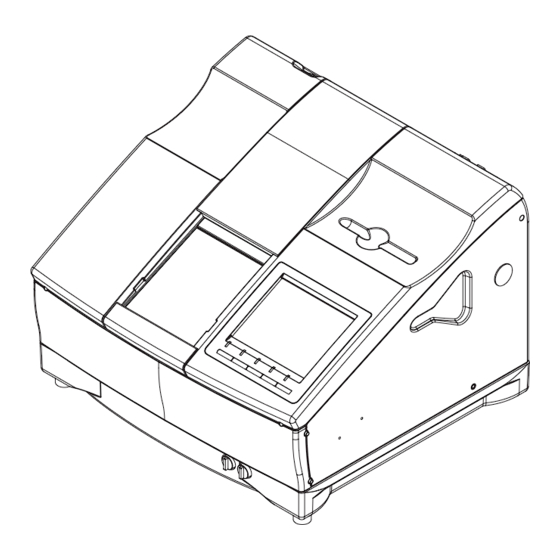
Page 124: Appearance
LLE11ARDA001A/E 8.3 Appearance Front view Pen tray Processing chamber Display Control panel Flow control valves Rear view Air inlet/outlet Ethernet connector Power switch RS-232C connector (BAR CODE) RS-232C connector (RS-232C) Cooling fan Cooling fan Outlet for cleaning water Outlet for cleaning water Outlet for vacuum cleaner Fuses Power connector... -
Page 125: Labels
LLE11ARDA001A/E 8.4 Labels Top view Processing chamber 8 - 5... - Page 126 LLE11ARDA001A/E Rear view 8 - 6...
-
Page 127: Error Message
LLE11ARDA001A/E 8.5 Error message Error indication Contents Causes and measures 101-Roughing was not Insufficient dressing of the Glass Roughing is not completed. completed wheel Insufficient dressing of the wheel 102-Finishing was not (This error message is displayed Finishing is not completed. completed when the rotating numbers of the θ... -
Page 128: Parameter List
LLE11ARDA001A/E 8.6 Parameter List 1. Menu mode Large category Medium category Small category Seting - Grinding Adjustment Size AXIS Bevel Position Groove Position Groove Depth Hole Diameter Hole Depth Tool Bit Diameter [mm] Flute Length [mm] Size Preset Metal (CR39/Hi Index) Plastic (CR39/Hi Index) Flat (CR39/Hi Index) Metal (Glass) - Page 129 LLE11ARDA001A/E Large category Medium category Small category Setting - Safety SFB Mode (Bevel) Bevel Small Rear Size (Bevel) Rear Size (Flat) Front Size (Bevel) Front Size (Flat) Medium Rear Size (Bevel) Rear Size (Flat) Front Size (Bevel) Front Size (Flat) Large Rear Size (Bevel) Rear Size (Flat)
- Page 130 LLE11ARDA001A/E 2. Parameter Setting mode Large category Medium category Small category Adjustment Feeler Height Feeler AXIS Bevel Position Bevel Position (Glass) Bevel Position (Polish) Polish Wheel Height Drill Adjustment Mode Finish Size CR39, Bevel CR39, Flat Hi Index, Bevel Hi Index, Flat Polyca./Acrylic, Bevel Polyca./Acrylic, Flat Trivex, Bevel...
- Page 131 LLE11ARDA001A/E Large category Medium category Small category Adjustment Safety Bevel Rear Position (Flat, Polish) Front Position (Flat, Polish) Rear Position (Bevel) Front Position (Bevel) Rear Position (Bevel, Polish) Front Position (Bevel, Polish) Rear AXIS (Flat) Front AXIS (Flat) Rear AXIS (Flat, Polish) Front AXIS (Flat, Polish) Rear AXIS (Bevel) Front AXIS (Bevel)
- Page 132 LLE11ARDA001A/E Large category Medium category Small category Setting - Grinding Idle Rotate Groove Drill Drill Speed Revolution (CR39/Hi Index) [ % ] Revolution (Polyca/Acrylic) [ % ] Revoluation (Trivex) [ % ] Feed (CR39/Hi Index) [mm/s] Feed (Polyca/Acrylic) [mm/s] Feed (Trivex) [mm/s] Slot (CR39/Hi Index) [mm/s] Slot (Polyca/Acrylic) [mm/s] Slot (Trivex) [mm/s]...
- Page 133 LLE11ARDA001A/E 3. System Setting mode Large category Medium category Small category Process Conter CR39 Hi Index Polyca. Acrylic Trivex Glass Total Wheel Rough Rough(Glass) Finish Polish Groove SFB Polish Drill Wheel Parameter Machine type (PL4) PLB-G (PLB-2R) Maintenance Drill Hole AXIS(S) Head Level Adjustment (Cutter) Measurement Data Trace Print Screen Enabled...
-
Page 134: Parameter List Of Inverter
LLE11ARDA001A/E 8.7 Parameter List of Inverter No. Parameter memo No. Parameter No. Parameter No. Parameter No. Parameter d 3 1000rpm Dress d 4 1600 2000rpm Polish nO-F. d 5 3000rpm Ck-L →tr IP d 6 4000rpm TRX/SoftModeFinish FrEE nO-F. 185 Eigenvalue 5000rpm TrIP nO-F.
Need help?
Do you have a question about the ME-1000 and is the answer not in the manual?
Questions and answers
how to replace water hose
Nidek marca error 501 saben que indica??