Table of Contents
Advertisement
Advertisement
Table of Contents

Subscribe to Our Youtube Channel
Related Manuals for Nidek Medical LE-9000EX Express


Summary of Contents for Nidek Medical LE-9000EX Express
- Page 1 NIDEK PATTERNLESS EDGER LE-9000EX Express/LE-9000DX Express OPERATOR’S MANUAL...
- Page 2 NIDEK CO., LTD. : 34-14, Maehama, Hiroishi-cho, Gamagori, Aichi 443-0038, Japan (Manufacturer) Telephone: (0533) 67-6611 Facsimile: (0533) 67-6610 NIDEK CO., LTD : 6th Floor, Takahashi Bldg., No.2, 3-chome, Kanda-jinboucho (Tokyo Office) Chiyoda-ku, Tokyo 101-0051, Japan Telephone: (03) 3288-0571 Facsimile: (03) 3288-0570 Telex: 2226647 NIDEK J NIDEK INCORPORATED : 47651 Westinghouse Drive, Fremont, California 94539, U.
- Page 3 BEFORE USE OR MAINTENANCE, READ THIS MANUAL. This Operator's Manual contains information necessary for the operation of the NIDEK PATTERNLESS EDGER Model LE-9000EX Express/LE-9000DX Express Type PC, Type PL4, Type PLB and Type PLB-2R. This manual includes the operating procedures, safety precautions, specifications, and information about accessories, and maintenance.
-
Page 4: Table Of Contents
4.3 Layouts ........................4-4 4.3.1 Inputting layout data into the ICE-2000 or LT-800SX ........4-4 4.3.2 Inputting layout data into the LE-9000EX Express/LE-9000DX Express ..4-4 4.3.2.1 Inputting the height from the lens outline ..........4-8 4.3.2.2 Layout of bifocal lenses ............... 4-9 4.3.2.3 Layout of progressive power lenses .......... - Page 5 Page 4.5.2.3 Auto grooving mode (LE-9000EX Express only) ......4-36 4.5.2.4 Guided grooving mode (LE-9000EX Express only) ......4-38 4.5.2.5 EX lens grooving mode (LE-9000EX Express only) ......4-42 4.5.3 Other processings ..................4-45 4.5.3.1 Processing half-eye lenses ..............4-45 4.5.3.2 Polishing (Types PL4, PLB and PLB-2R) ..........
- Page 6 8.11.3 Axis shift adjustment for polished lenses (Types PL4, PLB and PLB-2R) ... 8-24 8.12 Adjustment for Grooving (LE-9000EX Express only) .......... 8-26 8.12.1 Setting the initial value for depth and width (LE-9000EX Express only) ..8-26 8.12.2 Adjusting the groove position (LE-9000EX Express only) ......8-27 8.12.3 Adjusting the groove depth (LE-9000EX Express only) ......
-
Page 7: Introduction
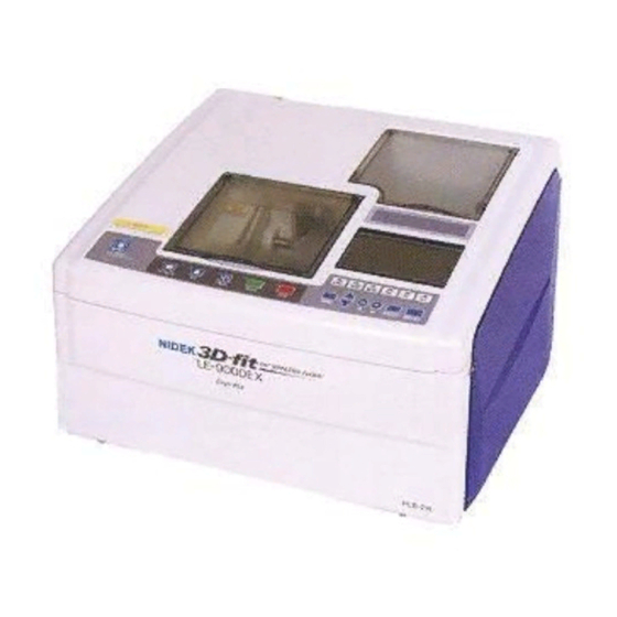
§ 1 INTRODUCTION 1.1 Outline of the Product This instrument is a fully-automatic lens edger which edges a lens into the shape of frames according to the traced data of the frames read in communication. This edger has a processing unit at the center front, a processing unit control panel at the front, a display panel at the right front. -
Page 8: Symbol Information
1 - 2 1.2 Symbol Information This symbol on the body indicates that caution should be taken. It is necessary to refer to Operator’s Manual before using the instrument. This symbol means caution for electric shock. The inside of the instrument includes high-voltage circuit. -
Page 9: Safety
§ 2 SAFETY In this manual, Signal Words are used to designate a degree or level of safety alerting. The definitions are as follows. WARNING: Indicates a potentially hazardous situation which, if not avoided, could result in death or serious injury. CAUTION: Indicates a potentially hazardous situation which, if not avoided, result in minor or moderate injury or a property damage accident. - Page 10 2 - 2 CAUTION • Never disassemble nor touch the internal structure. An electric shock or a failure of the instrument may occur. • Never yank the power cord to disconnect it from the wall outlet but hold the plug. This can damage the metal core of the cord and may result in a fire, a short circuit or an electric shock.
-
Page 11: In Storage
2 - 3 CAUTION • Be careful not to get your fingers caught when chucking (fixing) a lens. • When removing the lens cup with the cup remover, hold the lens with a soft cloth. If you hold the lens with bare hands, the lens edge may injure them. 2.2 In Storage CAUTION •... -
Page 12: Installation
2 - 4 2.4 Installation CAUTION • Use the instrument in the following conditions. - A dust free environment - A stable place with no tilt - A vibration and shock free environment • Install the instrument where it can be used at the following temperature and humidity. Use conditions Temperature: 5ºC - 40ºC... -
Page 13: In Wiring
2 - 5 2.5 In Wiring CAUTION • Do not put too much load on one electrical outlet. Abnormal heat generation may occur at the outlet in conjunction with the other devices. • Be sure to use a socket which meets the power specifications. If the line voltage is too high or low, the instrument may not give full performance. - Page 14 2 - 6 CAUTION • Be sure to use the specified fuses for replacement. Otherwise, a fire may occur. • Be sure to use the suitable dressing stick for wheel dressing. Otherwise, the wheel may be damaged and normal processing cannot be done. •...
-
Page 15: Disposal
2 - 7 CAUTION • Be sure to use the specified stocking filter only. Otherwise, the filter or water supply pipe may become clogged. • The stocking filter is disposable. Do not reuse it. A filter which has a rip or run in it does not function as a filter, and therefore, the water supply pipe may be clogged. -
Page 16: Labels
2 - 8 2.9 Labels The following labels provide safety information about each part. <Front view> <Rear view> (Only for 115 V AC regions) - Page 17 2 - 9 <Top view>...
-
Page 18: Safety Functions
2 - 10 2.10 Safety Functions For safety, various functions are provided. [Soundproof cover check function at the start of processing] Lens processing does not start unless the soundproof cover is closed. CAUTION • If the soundproof cover is opened during processing, the instrument will not stop. Be sure not to open the soundproof cover during processing since it is hazardous. - Page 19 2 - 11...
-
Page 20: Configuration
§ 3 CONFIGURATION [Whole system] Small articles box Soundproof cover Display panel Processing unit control panel Drawer Cabinet [Rear side of the main body] Power switch Cooling fan Contrast control Inlet RS-232C interface connector Connector for barcode scanner Outlet for pump 1 Outlet for pump 2... - Page 21 LE-9000EX Express/LE- The drain pipe and feedwater hoses are 9000DX Express does not contain a connected to the main body through the frame tracer.
- Page 22 3 - 3 [Processing unit] Feelers Chamber-cleaning nozzle Adapter Lens clamp Feedwater nozzles Wheels Grooving wheel Chamfering wheel...
- Page 23 Supplies water to the periphery of the lens • TYPE PLB during processing. • TYPE PLB-2R Grooving wheel (LE-9000EX Express only) This is the wheel to groove lenses for nylor frames. Chamfering wheel (LE-9000EX Express only) This is the wheel to chamfer lenses.
- Page 24 MTL/CEL (ZYL) Auto processing MTL/CEL (ZYL) Guided processing MTL/CEL (ZYL) EX lens processing PNT/NYL (blank) Flat (rimless) edging EX lens flat edging Auto grooving (LE-9000EX Express only) Guided grooving (LE-9000EX Express only) EX lens grooving (LE-9000EX Express only)
- Page 25 Turns ON/OFF the polishing mode. (This Fixes a lens with the lens clamp or releases key does not function for Type PC.) a lens from the clamp. (LE-9000EX Express only) Turns ON/OFF the simple frame chang- Turns ON/OFF the SFB mode. ing mode.
- Page 26 3 - 7 [Display Panel] • LAYOUT SCREEN Lens layout and prescription data input, etc. are performed on this screen. Soft processing mode indication SFB indication (LE-9000EX Express only) Minimum lens diameter Frame pupillary distance Pupillary distance Height of optical center...
- Page 27 Indicates the selected layout mode [ACT SFB indication (active mode), BF (bifocal mode), or PAS (passive mode)]. (LE-9000EX Express only) When the SFB mode is selected, Memory address (MEM) is shown. This address is used to store or to read →Both lens edges are chamfered.
- Page 28 ON). Bevel tilting amount • Groove simulation screen Sectional view position line Edge’s thickest point This screen is shown while a groove is simulated. (LE-9000EX Express only) Groove sectional view Groove curve Groove dip point Groove depth Groove width Edge’s thinnest point...
- Page 29 Adjust the bevel tip point diagonally- the groove dip point. opposite to the boxing center of the tilt One graduation of the scale is equal to base position. 0.2 mm. The value can be changed in 0.1 mm apply to the LE-9000EX Express increments. only.
- Page 30 3 - 11 • MENU screen This screen shows the selections such as Process counter, Wheel dressing, Size adjustment, and Bevel adjustment. It is u s e d t o p e r f o r m m a i n t e n a n c e o r adjustment of the edger.
-
Page 31: Operating Procedures
Reading traced data and inputting layout data →4.3.1 Inputting layout data into the ICE-2000 or LT-800SX (p. 4-4) →4.3.2 Inputting layout data into the LE-9000EX Express/LE-9000DX Express (p. 4-4) → 4.3.2.1 Inputting height from a lens outline (p. 4-8) → 4.3.2.2 Layout of bifocal lenses (p. 4-9) →... - Page 32 4 - 2 4.6 Checking the Lens Size → 4.6.1 Checking the lens size (p. 4-53) → 4.6.2 Retouching lenses (p. 4-53) 4.7 Processing the Opposite Lens (p. 4-55) End of processing Power-OFF...
-
Page 33: Preparation
4 - 3 4.2 Preparation 1. Plug the power cord into a wall outlet. CAUTION • Do not put too much load on one electrical outlet. It may cause a fire. • Prongs of the plug must be fully inserted into the socket. Incomplete connection may cause a fire. -
Page 34: Layouts
(Auto, Guided, EX, Blank) on the LE-9000EX Express/LE-9000DX Express (See p. 4-5). * The safety bevel size cannot be specified on the LE-9000EX Express. Safety bevels of the same size will be made even if the chamfering mode (Small, Middle, Large, Special) is specified. - Page 35 4 - 5 CAUTION • Be sure to specify the correct lens material. If not, the useful life of the processing wheel may be shortened. 2) Select beveling or flat (rimless) edging with [MTL, CEL (ZYL), PNT, NYL] Flat (rimless) edging ⇒ Select [PNT] or [NYL]. Beveling ⇒...
- Page 36 Press again to cancel the polishing mode. 6) Press to turn ON the SFB mode. (LE-9000EX Express only) The LED beside lights up, and is shown on the display panel.
- Page 37 4 - 7 2) Input the height of the optical center. Align the cursor to and input the height of the optical center from the rim center with 3) To correct the finished lens size, align the cursor to and input the corrective value with e.g.
-
Page 38: Inputting The Height From The Lens Outline
4 - 8 4.3.2.1 Inputting the height from the lens outline 1. Select an inputting form. Align the cursor to and select either of the following with PD : Height from the optical center straight down to the point on the lens outline. BT : Height from the point level with the optical center straight down to the lowest point on the lens outline. -
Page 39: Layout Of Bifocal Lenses
4 - 9 4.3.2.2 Layout of bifocal lenses 1. Select processing conditions. See Step 2 of “4.3.2 Inputting layout data into the LE-9000EX Express/LE-9000DX Express” (p. 4-4). 2. Select (bifocal) for the layout mode. 3. Input the prescribed PD for near vision at 4. -
Page 40: Layout Of Progressive Power Lenses
4 - 10 4.3.2.3 Layout of progressive power lenses 1. Select processing conditions. See Step 2 of “4.3.2 Inputting layout data into the LE-9000EX Express/LE-9000DX Express” (p. 4-4). 2. Select (Active) for the layout mode. 3. Input the prescribed PD at 4. -
Page 41: Inputting Eye Point Layout Data
4 - 11 4.3.2.4 Inputting eye point layout data This is the form to determine the optical center by inputting the distances to the nasal and bottom sides of the lens outline. This form serves to specify the position of the eye point, which is marked on dummy lenses, as the optical center. -
Page 42: Blocking Lenses
4 - 12 4.4 Blocking Lenses The blocking position of the suction cup varies with the layout mode (Active mode, Bifocal mode, Passive mode). 4.4.1 Blocking in active mode 1. Mark at the optical center of a lens with a lensmeter. -
Page 43: Blocking In Passive Mode
4 - 13 4.4.2 Blocking in passive mode This is the procedure to block at the rim center by decentering the optical center. When PAS (Passive) is selected for the layout mode, how much and in what direction the optical center should be decentered appears at PAS after lens layout is finished. -
Page 44: Blocking Bifocal Lenses
4 - 14 4.4.3 Blocking bifocal lenses When BF (bifocal) is selected for the layout mode, a lens is blocked at the specified value UP and OUT position from the top line center of the segment. Be sure to block the lens as instructed below since the edger processes the lens with the specified values. -
Page 45: Processings
4 - 15 4.5 Processings The processing mode is specified with See Step 2 of “4.3.2 Inputting layout data into the LE-9000EX Express/LE-9000DX Express” (p. 4-4). Processing mode setting setting Auto processing mode (see p. 4-17) MTL/CEL (ZYL) Beveling Guided processing mode (see p. 4-20) MTL/CEL (ZYL) EX lens processing mode (see p. - Page 46 4 - 16 NOTE • EX lenses cannot be processed in the auto processing mode and guided processing mode. Process an EX lens in the EX lens processing mode. See “4.5.1.4 EX lens processing mode” (p. 4-27). • Cataract lenses cannot be processed in the auto processing mode. Process a cataract lens with the bevel curve profiling the rear surface in the guided processing mode.
-
Page 47: Auto Processing Mode
4 - 17 4.5.1.1 Auto processing mode In this mode, a computer-calculated bevel is produced on the lens edge. 1. Check the processing conditions. : MTL or CEL (ZYL) : AUT 2. Set a lens to the adapter in the processing unit. Top mark •... - Page 48 Polishing (Only when is selected with Type PLB or PLB-2R.) ↓ Chamfering (Only when is selected.)(LE-9000EX Express only) ↓ Processings are complete. [The Layout screen returns.] When the screen changes to the Bevel simulation screen in Step , the sectional view position line rotates along the traced outline, and the bevel section at that position will be shown.
- Page 49 4 - 19 NOTE • Be sure to move a glass lens within the roughing wheel for glass lenses. If the glass lens contacts the other wheels, it may damage the wheels or the glass lens may crack. • The adjusted contact position with the wheel is effective only during the roughing of one lens.
-
Page 50: Guided Processing Mode
4 - 20 4.5.1.2 Guided processing mode This is the mode to input the value of the bevel curve and bevel position. 1. Check the processing conditions. : MTL or CEL (ZYL) : GUI 2. Set a lens to the adapter in the processing unit. - Page 51 4 - 21 6. Adjust the bevel position. (a) Changing the bevel position only at the part where the edge is thick B CRV 1) Align the cursor to 2) Change the bevel curve value to move the bevel position toward the front or rear surface of the lens.
- Page 52 4 - 22 (b) Changing the position of the whole bevel parallel to itself 1) Align the cursor to 2) Press to simulate the bevel at the point where the edge is thinnest ( ). 3) Change the bevel tip point value to move the bevel position toward the front or rear surface of the lens.
- Page 53 ↓ Polishing (Only when is selected with Type PLB or PLB-2R.) ↓ Chamfering (Only when is selected.)(LE-9000EX Express only) ↓ Processings are complete. [The Layout screen returns.] 10. Remove the lens. WARNING • Open the soundproof cover after making sure that the wheels have stopped completely.
-
Page 54: Guided Processing Mode (Tilting Function)
4 - 24 4.5.1.3 Guided processing mode (tilting function) The tilting function of the bevel is available in the guided processing mode, in which the bevel curve can be specified manually. If the difference in width between the edge’s thickest point and thinnest point is extreme, the mounted lens will not look nice. - Page 55 4 - 25 B CRV 3) Align the cursor to with , and set the bevel curve value with Press once to delete A (Auto-curve), and then set the desired value. e.g.) A4.3: A bevel position is computer-calculated from the ratio. 4.3: A bevel position is calculated from the spherical curve of the lens.
- Page 56 4 - 26 3. Restart processing. Press to restart processing. If the bevel is completely off the lens edge, two short beeps will sound. The sectional view position line automatically rotates along the whole traced outline and the bevel section at each position will be shown.
-
Page 57: Ex Lens Processing Mode
4 - 27 4.5.1.4 EX lens processing mode This mode serves to process EX lenses. In this mode, the beveling which has the curve profiling the rear surface is performed. As for a cataract lens which has a large dilation on its front convex surface, edge a lens in the EX lens edging mode if the lens processing cannot be performed in the guided processing mode (rear base curve) due to a lens shape measurement error. - Page 58 ↓ Polishing (Only when is selected with Type PLB or PLB-2R.) ↓ Chamfering (Only when is selected.)(LE-9000EX Express only) ↓ Processings are complete. [The Layout screen returns.] 7. Remove the lens. WARNING • Open the soundproof cover after making sure that the wheels have stopped completely.
- Page 59 4 - 29 Concrete example of the tilting function The procedures of processing EX lenses with the tilting function are described. To use the tilting function, it is necessary to set the parameter “TILT Function” to “Exec”. See “5.2 Parameter Settings” (p. 5-2). EX lenses have the distance part on their upper half and the near part on their lower half as in the figure, and the difference between the top edge width and the bottom one is wide.
- Page 60 4 - 30 Inputting a tilting amount The bevel position has been moved backward in Step though the upper part of the edge is thick. Move the bevel forward by inputting a minus value to “TILT”. In doing so, always observe the bevel on the boundary between the distance and near parts.
-
Page 61: Flat (Rimless) Edging
4 - 31 4.5.2 Flat (rimless) edging With the LE-9000DX Express, only flat edging is available. With the LE-9000EX Express, grooving which makes a groove for nylor frames after flat edging is also available. The EX lens flat edging mode is also available for EX lenses in normal flat edging. - Page 62 Polishing (Only when is selected with Type PL4, PLB or PLB-2R.) ↓ Chamfering (Only when is selected.)(LE-9000EX Express only) ↓ Processings are complete. [The Layout screen returns.] * The processing order may change according to the lens material. 5. Remove the lens.
- Page 63 4 - 33 [Addition of grooving](LE-9000EX Express only) When the parameter “To add safety bevel” is set to “Exec”, grooving can be additionally performed (except for glass lenses) after the flat edging with the frame setting “NYL”. However, as well as retouching, this cannot be performed such as when removing the suction cup, switching R/L, or reading other frame data.
-
Page 64: Ex Lens Flat (Rimless) Edging Mode
4 - 34 4.5.2.2 EX lens flat (rimless) edging mode This is the mode to make lens shape measurement of the front surface and to achieve flat edging of EX lenses with higher accuracy. (In the normal flat edging mode, the lens shape measurement of EX lenses cannot be made.) Especially, this mode is effective when polishing is selected to obtain polishing with high accuracy. - Page 65 4 - 35 4. Start processing. Press Lens shape measurement ↓ Roughing ↓ Finishing ↓ Polishing (Only when is selected with Type PL4, PLB or PLB-2R.) ↓ Chamfering (Only when is selected.) ↓ Processings are complete. [The Layout screen returns.] * The processing order may change according to the lens material.
-
Page 66: Auto Grooving Mode (Le-9000Ex Express Only)
4 - 36 4.5.2.3 Auto grooving mode (LE-9000EX Express only) This is the mode to groove a lens at the computer-calculated position and curve after flat edging. NOTE • In the grooving mode, glass lenses cannot be processed. 1. Check the processing conditions. - Page 67 4 - 37 NOTE • If the thinnest lens edge is less than the default, grooving is not performed. At that time, the message “Lacked lens thickness” will appear after the lens shape measurement, and then the instrument stops. Pressing goes to the Groove simulation screen.
-
Page 68: Guided Grooving Mode (Le-9000Ex Express Only)
4 - 38 4.5.2.4 Guided grooving mode (LE-9000EX Express only) This is the mode to make a groove for nylor frames at the position and curve input manually after flat edging. NOTE • In the grooving mode, glass lenses cannot be processed. - Page 69 4 - 39 5. Simulate the groove section at each point of Sectional view position line the outline on the screen. : The sectional view position line rotates clockwise. : The sectional view position line rotates counterclockwise. To stop the line movement, press again.
- Page 70 4 - 40 : The curve of the front base curve (FRNT), rear base curve (REAR), or ratio will be selected. → Specified curve value → Front base curve → Rear base curve → Ratio (curve profiling (curve profiling the front surface the rear surface of a lens) of a lens)
- Page 71 4 - 41 7. Check the groove section. 1) Press to turn off the cursor. 2) Simulate the whole groove to see if the desired groove is obtained. See Step 5 on page 4-39. 8. Repeat Steps 5 - 7 until the desired groove is obtained.
-
Page 72: Ex Lens Grooving Mode (Le-9000Ex Express Only)
4 - 42 4.5.2.5 EX lens grooving mode (LE-9000EX Express only) This is the mode to flat edge the EX lens and make a groove for nylor frames. In this mode, the groove is set to the curve of the rear lens surface. - Page 73 4 - 43 NOTE • If the thinnest lens edge is less than the default, grooving is not performed. At that time, the message “Lacked lens thickness” will appear after the lens shape measurement, and then the instrument stops. Pressing goes to the Groove simulation screen.
- Page 74 4 - 44 6. Start processing. Press Roughing ↓ Finishing ↓ Polishing (Only when is selected with Type PL4, PLB or PLB-2R.) ↓ Grooving ↓ Chamfering (Only when is selected.) ↓ Processings are complete. [The Layout screen returns.] * The processing order may change according to the lens material. 7.
-
Page 75: Other Processings
4 - 45 4.5.3 Other processings 4.5.3.1 Processing half-eye lenses When the distance from the blocking point to the position of the edge-to-be is short and the lens adapter or lens clamp may contact the wheels, the mark of the optical center will change from is indicated, replace the lens adapter, lens clamp, and lens cup with the ones for half-eye lenses by the following procedure. - Page 76 4 - 46 3. Block the lens with the half-eye lens cup. 1) Stick the provided double-coated adhesive tape for half-eye lenses to the half-eye lens cup. (Double-coated adhesive tape for half-eye lenses is supplied only for the NIDEK type.) If you use the conventional double-coated adhesive tape, cut off the excess part along the edge of the cup.
- Page 77 4 - 47 NOTE • Setting to disable displaying the message for half-eye lenses is available. When the lens adapter and lens clamp for half-eye lenses are used all the time, the operation will be smooth without stopping the instrument. See “5.2 Parameter Settings”...
-
Page 78: Polishing (Types Pl4, Plb And Plb-2R)
4 - 48 4.5.3.2 Polishing (Types PL4, PLB and PLB-2R) This is the mode to polish the lens edge to save the time required to buff the lens edge after finishing. Press to set the POL mode before starting processing with NOTE •... -
Page 79: Chamfering (Le-9000Ex Express Only)
4 - 49 4.5.3.3 Chamfering (LE-9000EX Express only) Before processings are completed, chamfering can be performed. Press to set the SFB mode before starting processing with The LED beside lights up, and shown on the display panel. ⇒ Both lens edges are chamfered. -
Page 80: Simple Frame Changing Mode
4 - 50 4.5.3.4 Simple frame changing mode This is the mode to process a lens by performing lens shape measurement at 1.5 mm inside of the bevel tip point when the lens size is not large enough for frame changing, etc. Before starting processing with , place the instrument into the simple frame... -
Page 81: Soft Processing
4 - 51 4.5.3.5 Soft processing Displayed only when the soft processing mode is selected. This is the processing method to perform the roughing process more precisely. Even though the processing time is extended a little, the processing sound and axis shift during processing are reduced. -
Page 82: Inputting The Frame Tilt Angle In Flat Edging
4 - 52 4.5.3.6 Inputting the frame tilt angle in flat edging To increase the finished PD accuracy, correction is made using the frame tilt angle measured during tracing. For nylor or two-point frames, however, the frame tilt angle cannot be measured because the pattern is traced. -
Page 83: Checking The Lens Size
4 - 53 4.6 Checking the Lens Size Check the lens size after processing is completed. If the lens is too large, retouch it to correct the size. 4.6.1 Checking the lens size Fit the lens in the rim and measure the gap at the rim joint. NOTE •... - Page 84 Moreover, if “GUI” is selected, any changes other than the groove depth and width to a larger size cannot be made on the Simulation screen. [Retouching of the safety bevel](LE-9000EX Express only) Retouching of the safety bevel can be performed by the same procedure with “[Addition of chamfering]”...
-
Page 85: Processing The Opposite Lens
4 - 55 4.7 Processing the Opposite Lens 1. Change the lens to be processed. Press to switch the lens to be processed. 2. Process the opposite lens in the same manner. 4.8 Removing the Lens Cup When removing the lens cup (suction cup or lens cup), use the provided cup remover. Insert the cup remover into the lens cup, and remove the lens cup while prying the cup with the remover. -
Page 86: Treatment After Daily Use
4 - 56 4.9 Treatment after Daily Use 1. Clean the processing unit. Follow Steps 1- 4 in “8.1 Wheel Dressing” to water the processing unit and wash out the processing wastes with a brush. CAUTION • Be careful not to let water get inside the instrument. It may cause an instrument malfunction. -
Page 87: Daily Checks
4 - 57 4.10 Daily Checks 4.10.1 Daily check before use Check the following before use every day. It is recommended to provide a check list to make sure everything is checked. A. Is the wheel in proper condition? Check that there are no fractures, cracks or flaws on the wheel. CAUTION •... -
Page 88: Daily Check After Use
4 - 58 4.10.2 Daily check after use Check the following after the final use every day. It is recommended to provide a check list to make sure everything is checked. A. Is the power turned OFF? B. Is the processing unit well cleaned? C. -
Page 89: Periodical Check
4 - 59 4.11 Periodical Check It is recommended to perform an inspection every two years in order to use the instrument for a long time under normal conditions. In the periodical inspection, a performance check of the whole system and replacement of maintenance parts are done. If inspection is required, contact NIDEK or your authorized distributor. -
Page 90: Other Functions
Align the pointer (→) to “Process counter” and press The process count for each material will be shown.* For the LE-9000EX Express, to check the chamfered lens count and total processed count, move the pointer (→) downward with 3. Go back to the MENU screen. -
Page 91: Parameter Settings
5 - 2 5.2 Parameter Settings This function sets each parameter according to the operator's use. 1. Call up the MENU screen. Press 2. Call up the Parameter exchange mode screen. Press again. 3. Select the item whose parameter needs to be changed. - Page 92 5 - 3 5) Initial value of FPD : ± Factory setting: +70.0 [mm] This sets the initial FPD value. 6) Initial value of PD : ± Factory setting: +62.0 [mm] This sets the initial PD value. Press to input any PD value. The set value appears first on the Layout screen. 7) Layout preset : ±...
- Page 93 5 - 4 11) Layout memory : None, Exec Factory setting: Exec This is for selecting whether or not to call up layout data as well as the lens shape when calling up the data with the memory function. In the following screen, data in the area shows that it can be called up to the screen at each setting.
- Page 94 5 - 5 16) BF ChuckLayout Height : ± Factory setting: + 5 [mm] This is for setting the lens layout for blocking lenses. Specify the shifted values from the top line center of the segment in blocking bifocal lenses. When using the NIDEK Cen- tering device, Model CE-1, leave the setting at the factory setting (5 mm outside, 5 mm up) and never change it.
-
Page 95: Storing The Initial Screen
• ON/OFF of [whether or not to perform chamfering] (LE-9000EX Express only) Each value on the screen cannot be stored. For setting the respective preset values for FPD, PD, and height of the optical center, see “5.2 Parameter Settings” (p. 5-2). -
Page 96: Storing And Calling Up Traced Data (Built-In Memory)
5 - 7 5.4 Storing and Calling Up Traced Data (built-in memory) The edger is provided with a memory function, which stores traced data and lens layout data in their memory and calls them up whenever necessary. By storing a repetitive lens outline as standard data and calling it up with the function, the operator does not have to trace the same lens for each processing and can save time required for lens processing. -
Page 97: When The Edger Is Not Connected To The Barcode Scanner
5 - 8 5.4.1 When the edger is not connected to the barcode scanner The internal memory built into the standard type of instrument can store and manage the traced outline and lens layout data of 100 sets of frames. <Storing method>... -
Page 98: When The Edger Is Connected To The Barcode Scanner
5 - 9 5.4.2 When the edger is connected to the barcode scanner By connection of the edger to the optional barcode scanner, the barcode memory function, which stores traced outline and lens layout data for a maximum of 500 sets of frames, becomes available. The read barcode number is stored as the registered number of the data. - Page 99 5 - 10 NOTE • To cancel data storage to the memory after reading the barcode, press <Method for calling up> To store only the traced outline and not store the lens layout data, set the parameter “Layout memory” to “None” in advance (see p. 5-4). 1.
-
Page 100: Troubleshooting Guide
§ 6 TROUBLESHOOTING GUIDE In the event that the instrument does not work correctly, correct the problem according to the following table before contacting NIDEK or your authorized distributor. Symptoms Action The display does not show anything Replace fuses. See "8.4 Replacing Fuses" (p. 8-12). though the power is turned ON. -
Page 101: Storage
§ 7 STORAGE NOTE • Store the instrument in an environment free from dust and direct sunlight. Avoid storing the instrument in humid surroundings. • If the instrument will not be used for a long time, unplug the power cable from the wall outlet. -
Page 102: Maintenance
§ 8 MAINTENANCE 8.1 Wheel Dressing A clogged wheel requires a longer time for processing and makes the finished size inaccurate. It is necessary, therefore, to regularly dress the wheels. CAUTION • In the dressing mode, the cover sensor is released and the wheels turn with the soundproof cover open. - Page 103 8 - 2 3. Open the soundproof cover. 4. Start dressing. CAUTION • Apply the end surface of the dressing stick to the wheel, not the corner or the edge. Otherwise, the wheel may be damaged. • Hold the dressing stick with both hands. If the stick is held with one hand, the stick cannot be held strongly enough, the corner of the stick may collide with the wheel and damage it.
- Page 104 8 - 3 [Dressing the polishing wheel] 1) Press Water will run for a few seconds, and at the same time, wheels will begin to turn. 2) Wet the dressing stick well with running water. 3) Press to stop the water. 4) Apply the dressing stick gently to the turning wheel.
- Page 105 8 - 4 [Dressing the chamfering wheel](LE-9000EX Express only) When chamfering glass lenses frequently, dress the chamfering wheel. CAUTION • Apply the dressing stick gently. If the dress stick is applied forcefully, it may affect the chamfering amount. 1) Press The chamfering wheel will come out.
-
Page 106: Replacing The Water (When The Optional Fp-100 Is Equipped)
8 - 5 8.2 Replacing the Water and Filter (115V regions) The procedure differs depending on whether the optional FP-100 is equipped or not. 8.2.1 Replacing the water (when the optional FP-100 is equipped) Replace the processing water and stocking filter in the tank periodically. It is recommended that the water be replaced for every 100 lenses processed. - Page 107 8 - 6 6. Filter the processing water to seperate the processing waste and water. 1) Connect the special hose of the FP-100 to the filter joint on the tank. Press into the hose until you hear it click. 2) Set the function lever to “FILTER”. 3) Turn ON ( | ) the power switch on the FP-100.
-
Page 108: Replacing The Water (When The Optional Fp-100 Is Not Equipped)
8 - 7 10. Put the water into the tank up to the position Drain pipe connector illustrated in the right figure. Even when the filtered water is reused, add required water. Guide of water volume 11. Put the lid on the tank. 12. - Page 109 8 - 8 1. Take the tank out of the cabinet. Feedwater hoses Open the cabinet and draw the tank toward you. Drain pipe 2. Disconnect the two feedwater hoses. Drain pipe connector Press the red button on the hose to disconnect. 3.
- Page 110 8 - 9 10. Attach a new stocking filter to the drain pipe connector. Stocking filters cannot be reused. Use a new one. 11. Set the drain cover as it was (see the figure of Step 4). Place the drain cover in the drain pipe connector on the tank. Stocking filter Place it with the larger diameter side up.
-
Page 111: Replacing The Water And Filter (230V Regions)
8 - 10 8.3 Replacing the Water and Filter (230V regions) Replace the processing water and stocking filter in the tank periodically. It is recommended that the water be replaced for every 100 lenses processed. NOTE • When the message “Please Clean Tank & Pump and Replace Filter” appears and the processing is stopped, replace the processing water and stocking filter, and remove the waste accumulated on the drain pipe connector. - Page 112 8 - 11 9. Put the water into the tank. Put the water up to 80% (about 5 cm from the Rubber band top). The waste disposal becomes easier by spreading a poly sheet in the tank in advance. Stocking filter 10.
-
Page 113: Replacing Fuses
8 - 12 8.4 Replacing Fuses If the instrument can not be activated though the power switch is turned ON, the fuses may be blown. Replace the fuses with new ones. CAUTION • Be sure to turn OFF the power switch and pull out the power cable before replacing fuses. -
Page 114: Size Adjustment
8 - 13 8.6 Size Adjustment When an edged lens is mounted into frames, the lens does not always fit. In such cases, adjust the size by inputting the compensation value as follows. 1. Call up the MENU screen. Press 2. -
Page 115: Adjusting The Bevel Position
8 - 14 4. Go back to the Layout screen. Press twice. 5. Repeat Steps 1 - 4 until the lens size just fits the frame. 8.7 Adjusting the Bevel Position When the finished bevel of a lens is displaced from the designated position, adjust the bevel position by changing the bevel constant. - Page 116 8 - 15 3. Call up the Bevel adjustment screen. Align the pointer (→) to “Bevel adjustment” and press 4. Input the compensation value. ******************************** * * To shift the bevel toward the front side of the * Bevel adjustment * * * lens, press ********************************...
-
Page 117: Adjusting The Axis Shift
8 - 16 8.8 Adjusting the Axis Shift 8.8.1 Adjusting the axis shift for unpolished lenses When the finished axis angle of a lens is shifted from the designated angle, adjust it as follows. 1. Call up the MENU screen. Press 2. - Page 118 8 - 17 4. Go back to the MENU screen. Press 5. Go back to the Layout screen. Press twice. 6. Repeat Steps 1 - 5 until the correct axis angle is obtained...
-
Page 119: Adjusting The Lens Margin Allowed For Finishing
8 - 18 8.9 Adjusting the Lens Margin Allowed for Finishing The lens margin is compensated by the following procedure. 1. Call up the MENU screen. Press 2. Call up the Size adjustment screen. Align the pointer (→) to “Size adjustment” and press 3. -
Page 120: Pd Adjustment
8 - 19 4. Go back to the MENU screen. Press 5. Go back to the Layout screen. Press twice. 8.10 PD Adjustment If the PD value input on the Layout screen does not agree with the PD of the finished lens, adjust the PD amount of the finished lens by the following procedure. -
Page 121: Adjustment For Polishing
8 - 20 8.11 Adjustment for Polishing 8.11.1 If part of an edge is left unpolished (Types PL4, PLB and PLB-2R) 1. Call up the MENU screen. Press 2. Call up the Size adjustment screen. Align the pointer (→) to “Size adjustment” and press 3. - Page 122 8 - 21 4. Go back to the MENU screen. Press 5. Go back to the Layout screen. Press twice. 6. Repeat Steps 1 - 5 until the whole edge is polished evenly.* 7. Check the finished size after polishing. Check each material lens for beveling and flat edging (only flat edging with Type PL4).
- Page 123 8 - 22 3) Align the pointer (→) to the desired item with To adjust the beveled lens margin. For plastic or acrylic resin lenses: “Polish size (PLA, bevel)” For polycarbonate or trivex lenses: “Polish size (PC, bevel)” For high index plastic lenses: “Rough size (HPL, bevel)”...
-
Page 124: If The Front Edge Or Rear Edge Is Left Unpolished (Types Plb And Plb-2R)
8 - 23 8.11.2 If the front edge or rear edge is left unpolished (Types PLB and PLB-2R) The polished bevel position is adjusted by the following procedure. 1. Call up the MENU screen. Press 2. Call up the Size adjustment screen. Align the pointer (→) to “Bevel adjustment”... -
Page 125: Axis Shift Adjustment For Polished Lenses (Types Pl4, Plb And Plb-2R)
8 - 24 8.11.3 Axis shift adjustment for polished lenses (Types PL4, PLB and PLB-2R) If the lens edge is not polished completely even after adjustment is made with “POL Differential”, the axis angle may be shifted. Perform the adjustment of the axis angle by the following procedure. 1. - Page 126 8 - 25 e.g. As seen from the front of the lens, the upper left side is not polished, add 0.50 to the present value. Setting value: +1.00 → +1.50 e.g. As seen from the sight from the front of the lens, the upper right side is not polished, subtract 0.50 from the present value.
-
Page 127: Adjustment For Grooving (Le-9000Ex Express Only)
8 - 26 8.12 Adjustment for Grooving (LE-9000EX Express only) 8.12.1 Setting the initial value for depth and width (LE-9000EX Express only) 1. Call up the MENU screen. Press 2. Call up the Groove & SFB adjustment screen. Align the pointer (→) to “Groove & SFB adjustment”... -
Page 128: Adjusting The Groove Position (Le-9000Ex Express Only)
8 - 27 8.12.2 Adjusting the groove position (LE-9000EX Express only) When the finished groove of a lens is displaced from the designated position, adjust the groove position by changing the groove constant. 1. Check the groove position. 1) Perform grooving with G CRV: 5 : 5 and PNT: 0.0. -
Page 129: Adjusting The Groove Depth (Le-9000Ex Express Only)
8. Repeat Steps 1 - 7 until the groove position comes to the right position. 8.12.3 Adjusting the groove depth (LE-9000EX Express only) 8.12.3.1 Groove depth is not made as designated (LE-9000EX Express only) Groove depth should be made evenly. However, if the grooving is not made at the designated depth, adjust it by changing the constant value of the chamfering wheel. -
Page 130: Groove Depth Is Not Even (Le-9000Ex Express Only)
7. Repeat Steps 1 - 6 until the correct groove depth is achieved. 8.12.3.2 Groove depth is not even (LE-9000EX Express only) The axis angle of the chamfering wheel may be shifted. Perform the following adjustment. 1. Call up the MENU screen. - Page 131 8 - 30 3. Align the pointer (→ → → → → ) to “PLA GROOVE AXS const” or “PC GROOVE AXS const” with Groove depth of polycarbonate or trivex lenses is uneven: Specify “PC GROOVE AXS const”. Groove depth of other lenses is uneven: Specify “PLA GROOVE AXS const”.
-
Page 132: Adjustment For Chamfering (Le-9000Ex Express Only)
8 - 31 8.13 Adjustment for Chamfering (LE-9000EX Express only) 8.13.1 Setting the SFB mode and chamfering amount (LE-9000EX Express only) 1. Call up the MENU screen. Press 2. Call up the Groove & SFB adjustment screen. Align the pointer (→) to “Groove & SFB adjustment”... -
Page 133: Adjusting The Chamfering Amount (Le-9000Ex Express Only)
8.13.2 Adjusting the chamfering amount (LE-9000EX Express only) 8.13.2.1 Safety bevel is not made as designated (LE-9000EX Express only) Chamfering amount must be even in circumference. If chamfering is not performed at the designated width, however, adjust the chamfering amount by changing the compensation value of the SFB wheel position. - Page 134 8 - 33 4. Input the compensation value of the SFB wheel position on the Groove & SFB adjustment screen. 1) Call up the MENU screen. 2) Align the pointer (→) to “Groove & SFB adjustment” and press 3) Align the pointer (→) to the desired item. To adjust the front SFB in beveling: Set the parameter “SFB Wheel Pos.
-
Page 135: Chamfering Amount Is Not Even
8 - 34 8.13.2.2 Chamfering amount is not even If the chamfering amount is not even in circumference, the chamfering axis angle may be shifted. Make the adjustment of the chamfering axis angle. 1. Call up the MENU screen. Press 2. -
Page 136: List Of Consumable Articles
8 - 35 6. Go back to the Layout screen. Press twice. 7. Repeat Steps 1 - 6 until the chamfering amount becomes even. 8.14 List of Consumable Articles Articles Order No. Dressing stick for roughing wheel 41002-M612 Dressing stick for finishing wheel 41002-M611 Dressing stick for polishing wheel 40140-M610... -
Page 137: Specifications
Manual-input groove position and curve Polishing (Types PL4, PLB, and PLB-2R) Chamfering * Grooving and chamfering are available to the LE-9000EX Express only. Processing lenses Glass, plastic, high index plastic, polycarbonate, acrylic resin, and trivex lenses (except for glass with Type PLB) Processing range Max. - Page 138 9 - 2 Adjustable range FPD: 30.0 - 99.5 mm (increment: 0.5 mm) 30.0 - 99.5 mm (increment: 0.5 mm) 1/2 PD: 15.0 - 49.75 mm (Step: 0.25 mm) Vertical layout: ±15.0 mm (increment mm) Horizontal layout: ±9.9 mm (increment: 0.1 mm) Size adjustment: ±9.95 mm (increment: 0.05 mm) Bevel position :...
- Page 139 9 - 3 Water supply system Pump circulation Other functions Layout: Active, passive, bifocal Layout input item: FPD (DBL) PD (1/2 PD) Vertical layout * Eye point layout function is available. Retouching function: Available (Memory function is available.) Frame memory function: Standard storable data 100 sets * The optional barcode scanner allows up to 500 sets of data to be stored.
- Page 140 9 - 4 Environmental conditions (In transport/storage) Temperature: –25ºC - 70ºC Humidity: 10% - 100% Pressure: 700 hPa - 1060 hPa (The conditions above indicate the state of the instrument packed.) Environmental conditions (In use) Setting location: Indoor Temperature: 5ºC - 40ºC Humidity: Relative humidity does not exceed 50% at a maximum temperature of 40ºC.
-
Page 141: Accessories
§ 10 ACCESSORIES 10.1 NIDEK-type Accessories Suction cup ......................3 pcs. Lens cup ....................... 5 pcs. Double-coated adhesive tape ................100 sheets Half-eye lens cup (blue) ..................5 pcs. Half-eye lens cup (white) ..................5 pcs. Half-eye lens cup (pink) ..................5 pcs. Double-coated adhesive tape for half-eye lenses .......... -
Page 142: Santi-Type Accessories
10 - 2 10.3 SANTI-type Accessories Double-coated adhesive tape ................100 sheets Half-eye lens clamp ..................... 1 pc. Dressing stick for the roughing wheel (WA80K)..........1 pc. Dressing stick for the finishing wheel (WA320K) ..........1 pc. Dressing stick for the polishing wheel (WA4000) ..........1 pc. Power cord ...................... -
Page 143: Appendix Asupplement
( See *4 of p. 4-7. See "4.3.2 Inputting layout data into the LE-9000EX Express/LE-9000DX Express" (p. 4-4). Inputting DBL Optical center This is the form to input DBL (distance between the nasal ends of the right and left rims) instead of FPD. -
Page 144: Selection Of Blocking
A - 2 (2) Selection of lenses and layout Bifocal lenses Progressive power lenses See "4.3.2.2 Layout of bifocal lenses" See "4.3.2.3 Layout of progressive (p. 4-9). power lenses" (p. 4-10). A.2 Selection of Blocking Active mode Passive mode H o r i z o n t a l l y d e c e n t e r i n g amount V e r t i c a l l y... -
Page 145: Selection Of Processing
See "4.5.2.2 EX lens flat (rimless) (p. 4-31). edging mode" (p. 4-34). Adjusting bevel position Creating computer-calculated (LE-9000EX Express only) grooves (LE-9000EX Express only) Adjusting groove position See "4.5.2.2 Auto grooving mode" Select "NYL" and "GUI". (p. 4-36). ↓ Press ↓... - Page 146 A - 4 Chamfering Polishing lens edge (LE-9000EX Express only) See "4.5.3.2 Polishing" (p. 4-48). See "4.5.3.3 Chamfering" (p. 4-49). (2) Special processing Finished lens is too large for frames Retouching Change the size value. ↓ Press See "4.6 Checking the Lens Size" (p. 4- 53).
-
Page 147: Appendix Berror Code
ERROR CODE APPENDIX B The instrument is provided with the self-diagnostic function and runs checks which constantly monitor the working state during operation. If any failure occurs, the instrument will stop automatically and show the error code on the display panel. In the event of a failure, inform of the error code as well as the symptoms of the instrument. - Page 148 B - 2 ERROR CODE CONTENTS 0501 The chuck motor does not run. 0601 The chamfering/grooving wheel motor is abnormal (overcurrent). 0602 Initialization of the chamfering/grooving unit is abnormal. 0603 Processing end sensor error of the chamfering/grooving unit. Setting position of the processing end sensor of the chamfering/grooving unit 0604 is improper.
-
Page 149: Appendix Cglossary
Auto grooving mode In this mode, the groove curve and groove position are automatically calculated by the computer to determine the best values for grooving. (LE-9000EX Express only) Bifocal mode This mode is for laying out bifocal lenses. In this mode, a lens is blocked at 5 mm above and 5 mm outside from the top line center of the segment with a lens cup by using a centering device. - Page 150 Guided processing mode In this mode, bevel curve and bevel position can be specified manually. Guided grooving mode In this mode, groove curve and groove position for nylor frames can be specified manually. (LE-9000EX Express only) Half-eye lens processing For frames whose vertical width is short, the mark of the optical center becomes , and as soon as processing starts, the message “Use chuck for half-eye lens”...
- Page 151 INDEX Active mode ..........4-12 Finishing wheel........... 3-4 Adjusting the axis shift ......8-16 Flat (rimless) edging mode ....... 4-31 Adjusting the bevel position ..... 8-14 Flat (rimless) edging ......... 4-31 Adjusting the groove position....8-27 FPD ............3-7, 5-3 Adjusting the lens margin allowed for finishing Frame pupillary distance ......
- Page 152 Index - 2 Parameter exchange mode screen ....3-11 Tilt base position ....... 3-9, 4-24 Parameter settings ........5-2 TILT function (parameter) ......5-5 Passive mode ..........4-13 Tilting function ........ 4-24, 4-29 Periodical check ........4-59 Two-point..........4-31 PD ............3-7, 5-3 PD adjustment ..........
Need help?
Do you have a question about the LE-9000EX Express and is the answer not in the manual?
Questions and answers