
Related Manuals for Nidek Medical SE-9090 Supra


Summary of Contents for Nidek Medical SE-9090 Supra
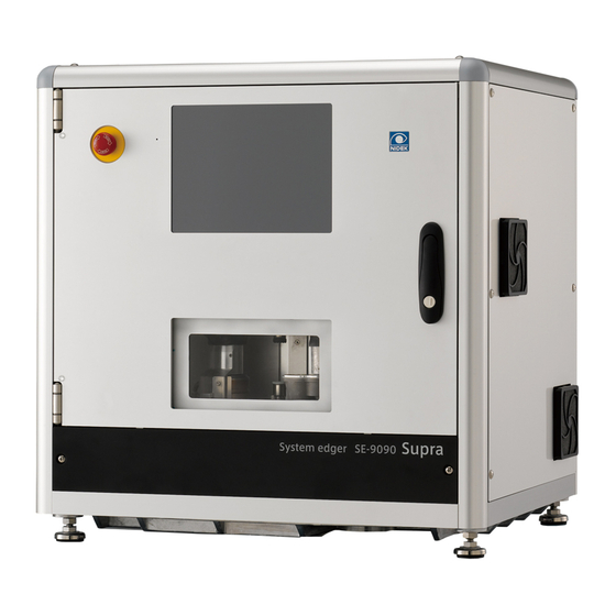
- Page 1 SYSTEM EDGER SE-9090 Supra SERVICE MANUAL September 2012 Pages in total: 350 LLE7D*RDA002B...
- Page 2 NIDEK CO., LTD. : 34-14, Maehama, Hiroishi-cho, Gamagori, Aichi 443-0038, Japan (Manufacturer) Telephone: +81-533-67-6611 Facsimile: +81-533-67-6610 NIDEK CO., LTD : 3F Sumitomo Fudosan Hongo Bldg., 3-22-5, Hongo, (Tokyo Office) Bunkyo-Ku, Tokyo 113-0033, Japan Telephone: +81-3-5844-2641 Facsimile: +81-3-5844-2642 NIDEK INCORPORATED : 47651 Westinghouse Drive, Fremont, California 94539, U. S. A. (United States Agent) Telephone: +1-510-226-5700 Facsimile: +1-510-226-5750...
-
Page 3: Table Of Contents
LLE7D*RDA002B Table of Contents 1. INTRODUCTION ........1 2. - Page 4 LLE7D*RDA002B 5 . 2 . 20. 2 Encoder value for rear feeler does not change ..34 5 . 2 . 21 Error 207 (LMU front feeler origin sensor error) ....35 5 .
- Page 5 LLE7D*RDA002B 5 . 2 . 58 Error 1991 (VCA lens material mismatch error) ....65 5 . 2 . 59 Error 2001 (Grooving unit initialization error) ....65 5 .
- Page 6 LLE7D*RDA002B 6. REMOVAL PROCEDURE ......93 6 . 1 Opening Front Cover ASSY ........93 6 .
- Page 7 LLE7D*RDA002B 7 . 2 . 8 Sensor ASSY (40274-CA34) ......131 7 .
- Page 8 LLE7D*RDA002B 7 . 5 . 4 Timing belt (40274-M736) of grooving ASSY....165 7 . 5 . 5 Grooving wheel (43131-M001)......166 7 .
- Page 9 LLE7D*RDA002B 8 . 14. 1 . 2 Using graph paper ....... 204 8 .
- Page 10 LLE7D*RDA002B 8 . 14. 10. 2 Groove position check ......254 8 . 14. 10. 3 Groove position adjustment.
- Page 11 LLE7D*RDA002B 9. SUPPLEMENT ........293 9 . 1 Appearance.
- Page 12 LLE7D*RDA002B This page is intentionally left blank.
-
Page 13: Introduction
To conduct repairs properly, thorough understanding of the contents in this manual is required prior to the service. Refer to the Operator’s Manual and Parts List for the SE-9090 Supra. In case the system cannot be repaired by the procedures described in this manual, please report the serial number of the system and details of the symptom or symptoms. - Page 14 LLE7D*RDA002B This page is intentionally left blank.
-
Page 15: Safety Precautions
LLE7D*RDA002B 2 SAFETY PRECAUTIONS 1 . Requirements for prior contact regarding repair 1 ) When conducting repairs described in the Service Manual or Service Manual Annex, prior contact with NIDEK is not necessary. 2 ) When conducting repairs not covered in the Service Manual or Service Manual Annex, prior contact with NIDEK in writing is required. - Page 16 LLE7D*RDA002B c . Cables are soldered properly. * Do not yank the cables with excessive force. Doing so could cause cable break- age. * Never perform servicing with wet hands. Doing so could cause electric shock or malfunction 9 ) The labeled area indicates high voltage.
-
Page 17: Specifications
LLE7D*RDA002B 3 SPECIFICATIONS 3.1 Safety Features For safe use, the edger is provided with the following features. 1 . Emergency stop button When a user determines that it is dangerous to continue processing, operation can be immedi- ately stopped by pressing the emergency stop button. 2 . -
Page 18: Processing Specifications
LLE7D*RDA002B 3.2 Processing Specifications 1 . Processing unit 1 ) Processing system Double spindle system, Patternless 2 ) Processing mode Auto beveling/Auto grooving (processing controlled by computer) Guided processing (Beveling/Grooving) Flat edging Safety beveling (Unavailable for high base curve bevel- ing with Type PLB-8S) High base curve beveling (Type PLB-8 only) Step beveling (High base curve beveling with Type... - Page 19 LLE7D*RDA002B 2 ) Minimum lens size a . Type PLA and PLB (width × height) Unit: mm Without safety beveling With safety beveling Flat edging Beveling Flat edging Beveling Pliable cup ø32.0 × 19.0 ø33.6 × 20.6 ø34.0 × 21.0 ø35.6 ×...
- Page 20 LLE7D*RDA002B 5 . Processing pressure Changeable in 15 levels (automatically controlled by the program) 6 . Wheel configurations 1 ) Type PLA Roughing wheel for plastic ø60 mm × 2 lenses Finishing wheel ø60 mm × 2 Safety beveling wheel ø60 mm (cone) ×...
-
Page 21: Interface Specifications
LLE7D*RDA002B 3.3 Interface Specifications 1 . Display 10.4-inch SVGA color LCD display (touch screen) 2 . Layout Optical center/Frame center 3 . Layout entry item FPD/DBL PD (1/2 PD) Optical center height (, PD, BT) 4 . Interface RS-232C: three ports For connection with a PC or blocker For connection with the barcode scanner For connection with the Robotic handling unit... - Page 22 LLE7D*RDA002B This page is intentionally left blank.
-
Page 23: Troubleshooting
LLE7D*RDA002B 4 TROUBLESHOOTING Turn on the instrument breaker. Is the initial screen displayed? 5.1 Nothing is Displayed on Screen (p13) Does any error message appear? 5.2 Error Message Appears (p16) After the initialization, does the Layout screen 5.3 Initialization of Instrument does not Complete appear automatically and the processing chamber (p76) door open? - Page 24 LLE7D*RDA002B This page is intentionally left blank.
-
Page 25: Subtroubleshooting
LLE7D*RDA002B 5 SUBTROUBLESHOOTING 5.1 Nothing is Displayed on Screen Turn off the instrument breaker, then reconnect both ends of the power cord. Is the problem resolved when the instrument breaker is turned on? Does the backlight of the color LCD module 5.1.1 Backlight of color LCD does not illuminate (40273-E020) illuminate? (p14) -
Page 26: Backlight Of Color Lcd Does Not Illuminate
LLE7D*RDA002B 5.1.1 Backlight of color LCD does not illuminate 5.1.2 Power supply check (p15) Is the voltage between the P601 (J11) 1st and 2nd Replace the cable ASSY (40273-CA07) (see 9.3 pins on the I/O board (40274-BA06) DC +24 V? [p298] and 9.4 [p299]). -
Page 27: Power Supply Check
LLE7D*RDA002B 5.1.2 Power supply check Is the power supply voltage proper (single phase: Install a stabilized power supply. AC 200 V 50/60Hz)? Are there any breaks in the power cord (CE) Replace the power cord. (40274-CA01)? Are there any breaks in the cable ASSY (40273- Replace the cable ASSY (40273-CA02) (see 9.3 CA02)? -
Page 28: Error Message Appears
LLE7D*RDA002B 5.2 Error Message Appears 5.2.1 Error 1 (Communication timeout error) Select the network setting properly (see 8.15 Is the network setting proper? [p276]). Are there any breaks in the LAN cable or RS232C Replace the LAN cable or RS232C cable. cable? Is the destination equipment set properly? Set the destination equipment properly. -
Page 29: Error 102 (Front Cover Error)
LLE7D*RDA002B 5.2.4 Error 102 (Front cover error) Is the front cover ASSY (40274-1100) closed? Close the front cover ASSY (40274-1100). When the front cover ASSY (40274-1100) is closed, does “Door” on the hardware test screen turn red (see 8.1.2.2 [p170])? When the front cover ASSY (40274-1100) is opened and the switch of the cable ASSY (40274- CA32) is turned on, does “Door”... -
Page 30: Error 103 (H-Axis Inside Limit Error)
LLE7D*RDA002B 5.2.5 Error 103 (H-axis inside limit error) Check the shape data. Is the shape data too small? Correct the shape data. Are there any abnormalities in the lens measurement data when bevel simulation is performed? Perform the LMU calibration (see 8.12.2 [p190]). -
Page 31: Error 104 (V-Axis Upper Limit Error)
LLE7D*RDA002B 5.2.6 Error 104 (V-axis upper limit error) Is safety beveling set for a thick lens or a Clear the safety beveling setting. decentering, sharply curved lens? Check the calibration data. Does it have any Calibrate the wheel positions (see 8.12.3 [p191]). -
Page 32: Error 105 (Roughing End Error)
LLE7D*RDA002B 5.2.7 Error 105 (Roughing end error) Does the lens material which is being processed Replace the lens or change the setting. correspond to the setting? Is the roughing wheel worn out? Replace the roughing wheel (see 7.1.27 [p125]). Does any cable or such interfere with the operation Change the route of the cable so that it does not of the RH axis ASSY (40274-2500) or LH axis interfere with the RH axis ASSY (40274-2500) or... -
Page 33: Error 106 (Finishing End Error)
LLE7D*RDA002B 5.2.8 Error 106 (Finishing end error) Does the lens material which is being processed Replace the lens or change the setting. correspond to the setting? Does the shape data show any discontinuous Correct the shape data. area? Is the finishing wheel worn out? Replace the finishing wheel (see 7.1.27 [p125]). -
Page 34: Error 107 (Polishing End Error)
LLE7D*RDA002B 5.2.9 Error 107 (Polishing end error) Does the lens material which is being processed Replace the lens or change the setting. correspond to the setting? Does the shape data show any discontinuous Correct the shape data. area? Is the polishing wheel worn out? Replace the polishing wheel (see 7.1.27 [p125]). -
Page 35: Error 108 (Grooving End Error)
LLE7D*RDA002B 5.2.10 Error 108 (Grooving end error) Does the lens material which is being processed Replace the lens or change the setting. correspond to the setting? Is the grooving wheel worn out? Replace the grooving wheel (see 7.5.5 [p166]). Is the grooving wheel clogged? Dress the grooving wheel (see 8.16.3 [p279]). -
Page 36: Error 109 (Step Beveling End Error)
LLE7D*RDA002B 5.2.11 Error 109 (Step beveling end error) Does the lens material which is being processed Replace the lens or change the setting. correspond to the setting? Is the step beveling wheel worn out? Replace the step beveling wheel (see 7.5.6 [p166]). -
Page 37: Error 110 (H- Axis Outside Limit Error)
LLE7D*RDA002B 5.2.12 Error 110 (H- axis outside limit error) Perform the wheel calibration (see 8.12.3 [p191]). 5.2.13 Error 111 (V-axis lower limit error) Are there any abnormalities in the lens measurement data when bevel simulation is Perform the LMU calibration (see 8.12.2 [p190]). -
Page 38: Error 201 (Lmu Feeler Off Error)
LLE7D*RDA002B 5.2.15 Error 201 (LMU feeler off error) Do the feelers come off during measurement after Increase the differential (see 8.1 [p167] and 9.8 roughing? [p317]). Is the lens diameter larger than that to be Change the lens layout if possible. If it is not processed by 1.0 mm or more? possible, use a lens with a larger diameter. -
Page 39: Error 202 (Lmu Lens Detection Error)
LLE7D*RDA002B 5.2.16 Error 202 (LMU lens detection error) Is a lens set? Set a lens. Replace the feelers (40271-M673) (see 7.5.2 Are the feelers (40271-M673) worn out? [p161]). Perform the LMU calibration (see 8.12.2 [p190]). Is the problem resolved? Replace the lens measuring ASSY (40274-6000) (see 7.1.17 [p111]). -
Page 40: Error 203 (Lmu Lens Thickness Error)
LLE7D*RDA002B 5.2.17 Error 203 (LMU lens thickness error) Is the edge thickness around the entire Replace the lens with one whose edge thickness is circumference of the lens sufficient? sufficient. Replace the feelers (40271-M673) (see 7.5.2 Are the feelers (40271-M673) worn out? [p161]). -
Page 41: Error 204 (Lmu Start And End Points Error)
LLE7D*RDA002B 5.2.18 Error 204 (LMU start and end points error) Is any foreign matter adhered to the lens? Remove the foreign matter from the lens. Do the feelers ride up on the protective tape on the Reduce the size of the protective tape on the lens. lens? Replace the lens with one that has a larger Is the lens diameter sufficient for processing? -
Page 42: Error 205 (Lmu Origin Sensor Error)
LLE7D*RDA002B 5.2.19 Error 205 (LMU origin sensor error) Is any processing waste adhered to the lens Clean the lens measuring window. measuring window (40274-6200)? When the LMU Front/Back button on the hardware test screen is pressed, does the LMU encoder 5.2.19.1 Lens measuring ASSY does not move value (to the right of the Back button) change and forward or backward (p31) -
Page 43: Lens Measuring Assy Does Not Move Forward Or Backward
LLE7D*RDA002B 5.2.19.1 Lens measuring ASSY does not move forward or backward Are there any breaks in the cable ASSY (40273- Replace the cable ASSY (40273-CA08) (see 9.3 CA08)? [p298] and 9.4 [p299]). Are there any breaks in the cable ASSY (40273- Replace the cable ASSY (40273-CA18) (see 9.3 CA18) for LMU PM? -
Page 44: Error 206 (Lmu Rear Feeler Origin Sensor Error)
LLE7D*RDA002B 5.2.20 Error 206 (LMU rear feeler origin sensor error) Do the feelers open or close when the LMU Open/ Close button on the hardware test screen is 5.2.20.1 Feelers do not open or close (p33) pressed? Does the LMU encoder value (to the left of the R- Clr button) change when the LMU Open/Close 5.2.20.2 Encoder value for rear feeler does not button on the hardware test screen is pressed... -
Page 45: Feelers Do Not Open Or Close
LLE7D*RDA002B 5.2.20.1 Feelers do not open or close Are there any breaks in the cable ASSY (40274- Replace the cable ASSY (40274-CA43) (see 9.3 CA43)? [p298] and 9.4 [p299]). Are there any breaks in the stepping motor (40273- Replace the stepping motor (40273-E029) (see E029)? 7.4.10... -
Page 46: Encoder Value For Rear Feeler Does Not Change
LLE7D*RDA002B 5.2.20.2 Encoder value for rear feeler does not change Are there any breaks in the rotary encoder (40273- Replace the rotary encoder (40273-E027) for EN-R E027) for EN-R? (see 7.4.8 [p153]). Are there any breaks in the cable ASSY (40274- Replace the cable ASSY (40274-CA43) (see 9.3 CA43)? -
Page 47: Error 207 (Lmu Front Feeler Origin Sensor Error)
LLE7D*RDA002B 5.2.21 Error 207 (LMU front feeler origin sensor error) Do the feelers open or close when the LMU Open/ Close button on the hardware test screen is 5.2.20.1 Feelers do not open or close (p33) pressed? Does the encoder value (to the left of the F-Clr button) change when the LMU Open/Close button 5.2.21.1 Encoder value for front feeler does not on the hardware test screen is pressed... -
Page 48: Encoder Value For Front Feeler Does Not Change
LLE7D*RDA002B 5.2.21.1 Encoder value for front feeler does not change Are there any breaks in the rotary encoder (40273- Replace the rotary encoder (40273-E027) for EN-F E027) for EN-F? (see 7.4.9 [p153]). Are there any breaks in the cable ASSY (40274- Replace the cable ASSY (40274-CA43) (see 9.3 CA43)? -
Page 49: Error 208 (Lmu Operation End Error)
LLE7D*RDA002B 5.2.22 Error 208 (LMU operation end error) Is processing waste adhered to the lens measuring Clean the lens measuring window. window ASSY (40274-6200)? When the LMU Front/Back button on the hardware test screen is pressed, does the LMU encoder 5.2.19.1 Lens measuring ASSY does not move value (to the right of the Back button) change and forward or backward (p31) - Page 50 LLE7D*RDA002B Replace the LMU board (40271-BA03) (see 7.3.3 [p136]). Is the problem resolved? Replace the I/O board (40274-BA06) (see 7.3.4 [p137]).
-
Page 51: Error 209 (Lmu Feeler Close Error)
LLE7D*RDA002B 5.2.23 Error 209 (LMU feeler close error) Is an extremely thick lens measured? Replace the lens with a thinner one. Is a decentering, sharply curved lens measured? Replace the lens. When the LMU Open/Close button on the hardware test screen is pressed, do the feelers open or close 5.2.20.1 Feelers do not open or close (p33) (see 8.1.2.2 [p170])? -
Page 52: Error 210 (Lmu Feeler Origin Sensor Off Error)
LLE7D*RDA002B 5.2.24 Error 210 (LMU feeler origin sensor off error) Does anything interfere with the feeler arm? Remove the interfering object. Are HH4 × 6 (n = 2) fastening the cam ASSY Tighten HH4 × 6 (n = 2) fastening the cam ASSY (40273-6101) loosened? (40273-6101). -
Page 53: Error 215 (Lmu Front Feeler Encoder Error)
Replace the main board (44501-BA01) (see 7.3.1 [p135]). 5.2.29 Error 304 (EEPROM data error) Because the EEPROM data is not for the SE-9090 Supra, change it to the one for the SE- 9090 Supra by the procedure of program upgrade (see 8.20.1 [p286]). -
Page 54: Error 401 (Right Wheel Motor Or Inverter Error)
LLE7D*RDA002B 5.2.30 Error 401 (Right wheel motor or inverter error) When the spindle (402743-M711) of the right Replace the spindle (402743-M711) of the right processing ASSY (40274-7200) is rotated by hand, processing ASSY (40274-7200) (see 7.5.3.2 does it rotate smoothly? [p164]). -
Page 55: Error 402 (Left Wheel Motor Or Inverter Error)
LLE7D*RDA002B 5.2.31 Error 402 (Left wheel motor or inverter error) When the spindle (402743-M711) of the L spindle Replace the spindle (402743-M711) of the L block ASSY (40273-7200) is rotated by hand, does spindle block ASSY (40273-7200) (see 7.5.3.1 it rotate smoothly? [p162]). -
Page 56: Error 501 (Right H-Axis Origin Sensor Error)
LLE7D*RDA002B 5.2.32 Error 501 (Right H-axis origin sensor error) When the R-Wheel ←/→ button is pressed, does the R-Wheel encoder value (to the right of →) on 5.2.32.1 Right processing ASSY does not move the hardware test screen change and the right right or left (p45) processing ASSY (40274-7200) move to the right or left... -
Page 57: Right Processing Assy Does Not Move Right Or Left
LLE7D*RDA002B 5.2.32.1 Right processing ASSY does not move right or left Are there any breaks in the cable ASSY (40273- Replace the cable ASSY (40273-CA08) (see 9.3 CA08)? [p298] and 9.4 [p299]). Are there any breaks in the cable ASSY (40273- Replace the cable ASSY (40273-CA18) for CA18) for R.H.PM? R.H.PM... -
Page 58: Error 502 (Right V-Axis Origin Sensor Error)
LLE7D*RDA002B 5.2.33 Error 502 (Right V-axis origin sensor error) When the R-Wheel ↑/↓ button on the hardware test screen is pressed, does the R-Wheel encoder 5.2.33.1 Right processing ASSY does not move up value (to the right of ↓) change and the right or down (p47) processing ASSY (40274-7200) move up or down (see 8.1.2.2... -
Page 59: Right Processing Assy Does Not Move Up Or Down
LLE7D*RDA002B 5.2.33.1 Right processing ASSY does not move up or down Are there any breaks in the cable ASSY (40273- Replace the cable ASSY (40273-CA08) (see 9.3 CA08)? [p298] and 9.4 [p299]). Are there any breaks in the cable ASSY (40273- Replace the cable ASSY (40273-CA18) for R.V. -
Page 60: Error 503 (Left H-Axis Origin Sensor Error)
LLE7D*RDA002B 5.2.34 Error 503 (Left H-axis origin sensor error) When the L-Wheel ←/→ button on the hardware test screen is pressed, does the L-Wheel encoder 5.2.34.1 L spindle block ASSY does not move right value (to the right of →) change and the L spindle or left (p49) block ASSY (40273-7200) move to the right or left (see 8.1.2.2... -
Page 61: L Spindle Block Assy Does Not Move Right Or Left
LLE7D*RDA002B 5.2.34.1 L spindle block ASSY does not move right or left Are there any breaks in the cable ASSY (40273- Replace the cable ASSY (40273-CA07) (see 9.3 CA07)? [p298] and 9.4 [p299]). Are there any breaks in the cable ASSY (40273- Replace the cable ASSY (40273-CA18) for L.H.PM CA18) for L.H.PM? (see 9.3 [p298] and 9.4... -
Page 62: Error 504 (Left V-Axis Origin Sensor Error)
LLE7D*RDA002B 5.2.35 Error 504 (Left V-axis origin sensor error) When the L-Wheel ↑/↓ button on the hardware test screen is pressed, does the L-Wheel encoder value 5.2.35.1 L spindle block ASSY does not move up (to the right of ↓) change and the L spindle block or down (p51) ASSY (40273-7200) move up or down (see 8.1.2.2... -
Page 63: L Spindle Block Assy Does Not Move Up Or Down
LLE7D*RDA002B 5.2.35.1 L spindle block ASSY does not move up or down Are there any breaks in the cable ASSY (40273- Replace the cable ASSY (40273-CA07) (see 9.3 CA07)? [p298] and 9.4 [p299]). Are there any breaks in the cable ASSY (40273- Replace the cable ASSY (40273-CA18) for L.V. -
Page 64: Error 505 (Lower Rotation Axis Origin Sensor Error)
LLE7D*RDA002B 5.2.36 Error 505 (Lower rotation axis origin sensor error) When the L−θ CW/CCW button on the hardware test screen is pressed, does the L−θ encoder value (to the right of the CCW button) change and the 5.2.36.1 Lower shaft ASSY does not rotate (p53) lower shaft ASSY (40274-3000) rotate (see 8.1.2.2 [p170])? -
Page 65: Lower Shaft Assy Does Not Rotate
LLE7D*RDA002B 5.2.36.1 Lower shaft ASSY does not rotate Are there any breaks in the cable ASSY (40273- Replace the cable ASSY (40273-CA07) (see 9.3 CA07)? [p298] and 9.4 [p299]). Are there any breaks in the cable ASSY (40273- Replace the cable ASSY (40273-CA18) for L.R. CA18) for L.R. -
Page 66: Error 506 (Upper Rotation Axis Origin Sensor Error)
LLE7D*RDA002B 5.2.37 Error 506 (Upper rotation axis origin sensor error) When the U−θ CW/CCW button on the hardware test screen is pressed, does the U−θ encoder value (to the right of the CCW button) change and the 5.2.37.1 Upper shaft ASSY does not rotate (p55) rotation ASSY (40274-5200) rotate (see 8.1.2.2 [p170])? -
Page 67: Upper Shaft Assy Does Not Rotate
LLE7D*RDA002B 5.2.37.1 Upper shaft ASSY does not rotate Are there any breaks in the cable ASSY (40273- Replace the cable ASSY (40273-CA08) (see 9.3 CA08)? [p298] and 9.4 [p299]). Are there any breaks in the cable ASSY (40273- Replace the cable ASSY (40273-A18) for U.R. PM CA18) for U.R. -
Page 68: Error 507 (Right H-Axis Limit Error)
Adjust the tracer so that the tolerance in the between the circumference data received by the circumference is within ±1.0 mm. SE-9090 Supra and the circumference indicated on (Refer to the service manual for the tracer.) the standard frame within ±1.0 mm? Calibrate the wheel positions (see 8.12.3... -
Page 69: Error 509 (Left H-Axis Limit Error)
LLE7D*RDA002B 5.2.40 Error 509 (Left H-axis limit error) Perform the procedure as in “5.2.38 Error 507 (Right H-axis limit error)” (p56). 5.2.41 Error 510 (Left V-axis limit error) Perform the procedure as in “5.2.39 Error 508 (Right V-axis limit error)” (p56). 5.2.42 Error 511 (Right H-axis move end error) Perform the procedure as in “5.2.32 Error 501 (Right H-axis origin sensor error)”... -
Page 70: Error 601 (Chuck Open Error)
LLE7D*RDA002B 5.2.48 Error 601 (Chuck open error) With the Chuck Pow↑ / Pow↓ button on the hardware test screen, set the motor power value (to the left of Pow↑) to 15 (see 8.1.2.2 [p170]). When the Chuck Open/Pre/Main button on the hardware test screen is pressed, does the Chuck 5.2.48.1 Upper shaft ASSY does not move up or encoder value (to the right of the Main button) -
Page 71: Upper Shaft Assy Does Not Move Up Or Down
LLE7D*RDA002B 5.2.48.1 Upper shaft ASSY does not move up or down Are there any breaks in the cable ASSY (40273- Replace the cable ASSY (40273-CA08) (see 9.3 CA08)? [p298] and 9.4 [p299]). Are there any breaks in the cable ASSY (40273- Replace the cable ASSY (40273-CA18) for CA18) for CHUCK PM? CHUCK PM... -
Page 72: Error 602 (Chuck Close Error)
LLE7D*RDA002B 5.2.49 Error 602 (Chuck close error) With the Chuck Pow↑/Pow↓ button on the hardware test screen, set the motor power value (to the left of Pow↑) to 15 (see 8.1.2.2 [p170]). When the Chuck Open/Pre/Main button on the hardware test screen is pressed, does the Chuck 5.2.48.1 Upper shaft ASSY does not move up or encoder value (to the right of the Main button) down (p59) -
Page 73: Error 701 (Cover Open Error)
LLE7D*RDA002B 5.2.50 Error 701 (Cover open error) Are there any breaks in the cable ASSY (40274- Replace the cable ASSY (40274-CA13) (see 9.3 CA13)? [p298] and 9.4 [p299]). When the Cover Open/Close button on the hardware test screen is pressed, does the 5.2.50.1 Motorized cover ASSY does not operate motorized cover ASSY operate (see 8.1.2.2... -
Page 74: Motorized Cover Assy Does Not Operate
LLE7D*RDA002B 5.2.50.1 Motorized cover ASSY does not operate Are there any breaks in the cable ASSY (40274- Replace the cable ASSY (40274-CA13) (see 9.3 CA13)? [p298] and 9.4 [p299]). Are there any breaks in the cable ASSY (40274- Replace the cable ASSY (40274-CA19) (see 9.3 CA19)? [p298] and 9.4... -
Page 75: Error 801 (Sd Card Detection Error)
LLE7D*RDA002B 5.2.52 Error 801 (SD card detection error) Insert the SD card (44501-E030) (see 8.19.1 Is the SD card (44501-E030) inserted? [p284]). Replace the SD card (44501-E030) (see 8.19.1 [p284]). Is the problem resolved? Replace the main board (44501-BA01) (see 7.3.1 [p135]). -
Page 76: Error 808 (Usb Flash Drive Detection Error)
LLE7D*RDA002B 5.2.53 Error 808 (USB flash drive detection error) Is the USB flash drive (43501-E032) inserted? Insert the USB flash drive (43501-E032). Are there any breaks in the cable ASSY (40274- Replace the cable ASSY (40274-CA10) (see 9.3 CA10)? [p298] and 9.4 [p299]). -
Page 77: Error 1990 (Vca Receiving Data Overflow Error)
LLE7D*RDA002B 5.2.57 Error 1990 (VCA receiving data overflow error) Change the data sent from the VCA server. 5.2.58 Error 1991 (VCA lens material mismatch error) Change the data from the VCA server. 5.2.59 Error 2001 (Grooving unit initialization error) When the G-Wheel Front/Back button on the hardware test screen is pressed, does the grooving 5.2.59.1 Grooving ASSY does not move forward or ASSY (40274-7210) move forward/backward... -
Page 78: Grooving Assy Does Not Move Forward Or Backward
LLE7D*RDA002B 5.2.59.1 Grooving ASSY does not move forward or backward Are there any breaks in the cable ASSY (40274- Replace the cable ASSY (40274-CA28) (see 9.3 CA28)? [p298] and 9.4 [p299]). Replace the I/O board (40274-BA06) (see 7.3.4 [p137]). Is the problem resolved? Replace the stepping motor (80407-00217) for G_R PM (see 7.4.13... -
Page 79: Error 2003 (Step Beveling Overcurrent Error)
LLE7D*RDA002B 5.2.61 Error 2003 (Step beveling overcurrent error) Does the lens material which is being processed Replace the lens or change the setting. correspond to the setting? Is sufficient cooling water applied to the lens? Adjust the cooling water volume. When the G-Wheel CW/CCW button on the hardware test screen is pressed, is the step Replace the grooving ASSY (40274-721S) -
Page 80: Error 2004 (Grooving Motor Error)
LLE7D*RDA002B 5.2.62 Error 2004 (Grooving motor error) Are there any breaks in the cable ASSY (40274- Replace the cable ASSY (40274-CA27) (see 9.3 CA27)? [p298] and 9.4 [p299]). Replace the grooving ASSY (40274-721S) (see 7.1.22 [p119]). Is the problem resolved? Replace the I/O board (40274-BA06) (see 7.3.4 [p137]). -
Page 81: Error 2102 (Rv Motor Communication Error)
LLE7D*RDA002B 5.2.64 Error 2102 (RV motor communication error) Are there any breaks in the cable ASSY (40273- Replace the cable ASSY (40273-CA18) for R.V.PM CA18) for R.V.PM? (see 9.3 [p298] and 9.4 [p299]). Replace the closed loop motor driver (40274-E019) for R.V.PM (see 7.4.5 [p151]). -
Page 82: Error 2104 (Lv Motor Communication Error)
LLE7D*RDA002B 5.2.66 Error 2104 (LV motor communication error) Are there any breaks in the cable ASSY (40273- Replace the cable ASSY (40273-CA18) for the CA18) for L.V.PM? L.V.PM (see 9.3 [p298] and 9.4 [p299]). Replace the closed loop motor driver (40274-E019) for L.V.PM (see 7.4.5 [p151]). -
Page 83: Error 2106 (Lr Motor Communication Error)
LLE7D*RDA002B 5.2.68 Error 2106 (LR motor communication error) Are there any breaks in the cable ASSY (40273- Replace the cable ASSY (40273-CA18) for L.R.PM CA18) for L.R.PM? (see 9.3 [p298] and 9.4 [p299]). Replace the closed loop motor driver (40274-E019) for L.R.PM (see 7.4.5 [p151]). -
Page 84: Error 2108 (Lmu Motor Communication Error)
LLE7D*RDA002B 5.2.70 Error 2108 (LMU motor communication error) Are there any breaks in the cable ASSY (40273- Replace the cable ASSY (40273-CA18) for CA18) for LMUPM? LMUPM (see 9.3 [p298] and 9.4 [p299]). Replace the closed loop motor driver (40274-E019) for LMUPM (see 7.4.5 [p151]). -
Page 85: Error 2201 (Calibration Sensor Error)
LLE7D*RDA002B 5.2.71 Error 2201 (Calibration sensor error) Is the connector of the touch sensor type Connect the connector of the touch sensor type calibration jig (40300-0970) connected to the jack calibration jig (40300-0970) to the jack for for maintenance on the USB board? maintenance on the USB board (see 9.1 [p293]). -
Page 86: Error 2301 (I/O Board Error)
LLE7D*RDA002B 5.2.72 Error 2301 (I/O board error) Is the LAN straight cable (40274-E025) connected Connect the LAN straight cable (40274-E025) (see to P102 (J2) of the main board (44501-BA01) and 9.3 [p298] and 9.4 [p299]). P602 (J2) of the I/O board (40274-BA06)? Check the software version (see 8.20.4 [p289]). -
Page 87: Error 10002 (Emergency Button Is Pressed.)
LLE7D*RDA002B 5.2.74 Error 10002 (Emergency button is pressed.) Is the emergency stop button pressed? Release the emergency stop button. Are there any breaks in the cable ASSY (40274- Replace the cable ASSY (40274-CA31) (see 7.2.3 CA31)? [p129]). Replace the I/O board (40274-BA06) (see 7.3.4 [p137]). -
Page 88: Initialization Of Instrument Does Not Complete
LLE7D*RDA002B 5.3 Initialization of Instrument does not Complete Does any error message appear? 5.2 Error Message Appears (p16) 5.2.19.1 Lens measuring ASSY does not move forward or backward (p31) 5.2.20.1 Feelers do not open or close (p33) 5.2.32.1 Right processing ASSY does not move right or left (p45) 5.2.33.1 Right processing ASSY does not move up or down (p47) -
Page 89: Touch Panel Is Not Operational
LLE7D*RDA002B 5.4 Touch Panel is not Operational Are there any breaks in the flexible flat cable Replace the flexible flat cable (40274-E015) (see (40274-E015)? 9.3 [p298] and 9.4 [p299]). Calibrate the touch panel (see 8.16 [p277]). Is the problem resolved? Replace the color LCD module (40273-E020) (see 7.4.6... -
Page 90: External Data Cannot Be Received Properly
LLE7D*RDA002B 5.5 External Data cannot be Received Properly Is the communication setting proper? Set the network properly (see 8.15 [p276]). Is the cable type (cross or straight) proper? Connect a proper cable. Are there any breaks in the LAN cable or RS232C Replace the LAN cable or RS232C cable. -
Page 91: Lens Processing Is Not Performed Properly
LLE7D*RDA002B 5.6 Lens Processing is not Performed Properly 5.6.1 Cooling water does not come out Is the water inside the tank sufficient? Refill the tank with water. Is the valve of the inlet for cooling water open? Open the valve of the inlet for cooling water. Are the hoses for supplying cooling water and cleaning water and the power cord of the pump Connect them properly. - Page 92 LLE7D*RDA002B When the SSR1/SSR2/SSR3 button on the hardware test screen is pressed, does the voltage between the following P902 pins become DC +24 V Replace the I/O board (40274-BA06) (see 7.3.4 (see 8.1.2.2 [p170])? [p137]). SSR1: 1st and 2nd pins SSR2: 1st and 3rd pins SSR3: 1st and 4th pins Replace the SSR board (44501-BA09)
-
Page 93: Processing Time Is Overly Long
LLE7D*RDA002B 5.6.2 Processing time is overly long 5.6.2.1 Roughing time is overly long Does the lens material which is being processed Correct the setting. correspond to the setting? Does sufficient cooling water come out? 5.6.1 Cooling water does not come out (p79) Does any error message appear? 5.2 Error Message Appears (p16) Correct the shape data. -
Page 94: Finishing Time Is Overly Long Or Does Not Complete
LLE7D*RDA002B 5.6.2.2 Finishing time is overly long or does not complete Does the lens material which is being processed Correct the setting. correspond to the setting? Does sufficient cooling water come out? 5.6.1 Cooling water does not come out (p79) Adjust the orientation of the nozzle or the water Is the cooling water applied to the lens while flow volume with the valve of the inlet for the... -
Page 95: Safety Beveling Time Is Overly Long Or Does Not Complete
LLE7D*RDA002B 5.6.2.3 Safety beveling time is overly long or does not complete Does the lens material which is being processed Correct the setting. correspond to the setting? Does sufficient cooling water come out? 5.6.1 Cooling water does not come out (p79) Adjust the orientation of the nozzle or the water Is the cooling water applied to the lens while flow volume with the valve of the inlet for the... -
Page 96: Wheel Stops During Processing
LLE7D*RDA002B 5.6.3 Wheel stops during processing Is the spindle (40273-M711) running idle? Reattach the wheel (see 7.1.27 [p125]). Is the belt (40271-M765) worn out? Replace the belt (40271-M765) (see 7.4.1 [p140]). Replace the spindle(40273-M711) (see 7.5.3 Is the tension of the belt (40271-M765) proper? [p162]). -
Page 97: Axis Shift Occurs
LLE7D*RDA002B 5.6.5 Axis shift occurs Repair the product in which axis shift occurs (refer Does any axis shift occur in the used tracer, to the service manual for the corresponding blocker, or lensmeter? product). Does axis shift occur in the same direction during Adjust the axis (see 8.14.1 [p198]). -
Page 98: Lens Is Not Beveled Properly
LLE7D*RDA002B 5.6.6 Lens is not beveled properly Is the lens finish size proper? 5.6.4 Lens finish size is not proper (p84) Do the feelers ride up on the foreign matter Remove the foreign matter or protective tape. adhered to the lens or the protective tape? Perform the LMU calibration (see 8.12.2 [p190]). -
Page 99: Lens Is Not Safety Beveled Properly
LLE7D*RDA002B 5.6.7 Lens is not safety beveled properly In this instrument, safety beveling does not occur Is the bevel position on the rear edge within 0.5 when the bevel position on the rear edge is within mm from the bevel apex? 0.5 mm from the bevel apex. -
Page 100: Lens Is Not Polished Properly
LLE7D*RDA002B 5.6.8 Lens is not polished properly 5.6.8.1 Flat edge is not polished properly Is the lens finish size proper? 5.6.4 Lens finish size is not proper (p84) Dress the polishing wheel using the compound (see 8.17.1 [p280]). Is the problem resolved? Check the flat polish axis (see 8.14.4.3 [p220]). -
Page 101: Beveled Edge Is Not Polished Properly
LLE7D*RDA002B 5.6.8.2 Beveled edge is not polished properly Is the lens beveled properly? 5.6.6 Lens is not beveled properly (p86) Dress the polishing wheel using the compound (see 8.17.1 [p280]). Is the problem resolved? Are polishing marks more common along the lens Adjust flat polish axis (see 8.14.4.4 [p221]). -
Page 102: Safety Beveled Edge Is Not Polished Properly
LLE7D*RDA002B 5.6.8.3 Safety beveled edge is not polished properly Is the lens safety beveled properly? 5.6.7 Lens is not safety beveled properly (p87) Are there any burns on the polished surface of the 5.6.8.4 There are burns on polished surface of safety beveled edge? safety beveled edge (p91) Is the SFB polish size proper? -
Page 103: There Are Burns On Polished Surface Of Safety Beveled Edge
LLE7D*RDA002B 5.6.8.4 There are burns on polished surface of safety beveled edge Does sufficient cooling water come out? 5.6.1 Cooling water does not come out (p79) Dress the polishing wheel using the compound (see 8.17.1 [p280]). Is the problem resolved? Adjust SFB polish size (see 8.14.7.4 [p248]). - Page 104 LLE7D*RDA002B This page is intentionally left blank.
-
Page 105: Removal Procedure
LLE7D*RDA002B 6 REMOVAL PROCEDURE 6.1 Opening Front Cover ASSY 1 . Turn off the instrument breaker. 2 . Unlock the handle (40274-M156) with the provided key. Locked Unlocked 3 . Raise the handle (40274-M156). 4 . With the handle (40274-M156) raised, turn it 90°... -
Page 106: Left Panel (40274-M142)
LLE7D*RDA002B 6.2 Left Panel (40274-M142) 1 . Turn off the instrument breaker. 2 . Unscrew the machine screws (40274- M149 [n = 6]) to remove the left panel (40274-M142). If a USB flash drive is con- nected, disconnect it before removing the panel. -
Page 107: Exterior Panel Assy (40274-1200)
LLE7D*RDA002B 6.4 Exterior Panel ASSY (40274-1200) 1 . Turn off the instrument breaker. 2 . Disconnect the cables and hoses connected to the rear panel (40274-M141). 3 . Unscrew the machine screws (40274- M149 [n = 6]) to remove the exterior panel ASSY (40274-1200). -
Page 108: Top Panel (40274-M144)
M149 [n = 4]) to remove the top panel (40274-M144). 6.7 Attaching the Splatter Guard (40274-M051) Be sure to attach the splatter guard (40274-M051) when connecting the SE-9090 Supra Caution and Robotic Handling Unit (RHU-1000 series). 1 . Open the processing chamber door. -
Page 109: Replacement Procedure
LLE7D*RDA002B 7 REPLACEMENT PROCEDURE 7.1 ASSYs 7.1.1 Display ASSY (40274-1110) Replacement part: 40274-1110 1 . Open the front cover ASSY (see 6.1 [p93]). 2 . Remove the main board (44501-BA01) (see 7.3.1 [p135]). 3 . Disconnect P205 (J5) and P206 (J6) from the connection board (40274-BA02). 4 . -
Page 110: Motorized Cover Assy (40274-1120)
LLE7D*RDA002B 7.1.2 Motorized cover ASSY (40274-1120) Replacement part: 40274-1120 40274-M160 1 . Open the front cover ASSY (40274-1100) (see 6.1 [p93]). 2 . Remove the display ASSY (40274-1110) (see 7.1.1 [p97]). 3 . Remove the seal (40274-M160). 4 . Unscrew SB3 × 6 (n = 6) to replace the motorized cover ASSY (40274-1120). -
Page 111: F/L Support Assy (40274-1310)
LLE7D*RDA002B 7.1.4 F/L support ASSY (40274-1310) Replacement part: 40274-1310 1 . Open the front cover ASSY (40274-1100) (see 6.1 [p93]). 2 . Remove the following panels. 1 ) Left Panel (40274-M142) (See 6.2 [p94].) 2 ) Front Panel (40274-M146) (See 6.5 [p95].) 3 . -
Page 112: F/R Support Assy (40274-1320)
LLE7D*RDA002B 7.1.5 F/R support ASSY (40274-1320) Replacement part: 40274-1320 1 . Open the front cover ASSY (40274-1100) (see 6.1 [p93]). 2 . Remove the following panels. 1 ) Right Panel (40274-M143) (See 6.3 [p94].) 2 ) Front Panel (40274-M146) (See 6.5 [p95].) 3 . -
Page 113: R/L Support Assy (40274-1330)
LLE7D*RDA002B 7.1.6 R/L support ASSY (40274-1330) Replacement part: 40274-1330 1 . Remove the following panels. 1 ) Left Panel (40274-M142) (See 6.2 [p94].) 2 ) Exterior Panel ASSY (40274-1200) (See 6.4 [p95].) 3 ) Top Panel (40274-M144) (See 6.6 [p96].) 2 . -
Page 114: R/R Support Assy (40274-1340)
LLE7D*RDA002B 7.1.7 R/R support ASSY (40274-1340) Replacement part: 40274-1340 1 . Remove the following panels. 1 ) Left Panel (40274-M142) (See 6.2 [p94].) 2 ) Exterior Panel ASSY (40274-1200) (See 6.4 [p95].) 3 ) Top Panel (40274-M144) (See 6.6 [p96].) 2 . -
Page 115: R V-Axis Assy (40274-2300)
LLE7D*RDA002B 7.1.8 R V-axis ASSY (40274-2300) Replacement part: 40274-2300 Necessary tool: Spacer (40300-M951) 1 . Open the front cover ASSY (40274-1100) (see 6.1 [p93]). 2 . Remove the right panel (40274-M143) (see 6.3 [p94]). 3 . Enter Wheel replacement mode and raise the R V-axis ASSY (40274-2300) to the top (see 7.1.27 [p125]). -
Page 116: L V-Axis Assy (40274-2400)
LLE7D*RDA002B 7.1.9 L V-axis ASSY (40274-2400) Replacement part: 40274-2400 Necessary tool: Spacer (40300-M951) 1 . Open the front cover ASSY (40274-1100) (see 6.1 [p93]). 2 . Remove the left panel (40274-M142) (see 6.2 [p94]). 3 . Enter Wheel replacement mode and raise the L V-axis ASSY (40274-2400) to the top (see 7.1.27 [p125]). -
Page 117: R H-Axis Assy (40274-2500)
LLE7D*RDA002B 7.1.10 R H-axis ASSY (40274-2500) Replacement part: 40274-2500 1 . Remove the right panel (40274-M143) (see 6.3 [p94]). 2 . Enter Wheel replacement mode and raise the R H-axis ASSY (40274-2500) to the top (see [p94]). 3 . Disconnect the following connectors. 1 ) CN2 of closed loop motor driver MD01 (40274-E019) 2 ) P616 (J16) of the I/O board (40274-BA06) 4 . -
Page 118: L H-Axis Assy (40274-2600)
LLE7D*RDA002B 7.1.11 L H-axis ASSY (40274-2600) Replacement part: 40274-2600 1 . Remove the left panel (40274-M142) (see 6.2 [p94]). 2 . Enter Wheel replacement mode and raise the L H-axis ASSY (40274-2600) to the top (see [p94]). 3 . Disconnect the following connectors. 1 ) CN2 of closed loop motor driver MD03 (40274-E019) 2 ) P618 (J18) of the I/O board 4 . -
Page 119: Lower Rotation Axis Assy (40274-3000)
LLE7D*RDA002B 7.1.12 Lower rotation axis ASSY (40274-3000) Replacement part: 40274-3000 Liquid gasket (white, Three Bond 1211 or its equivalent) Necessary tool: Instrument stand allowing access to instrument interior from below 1 . Mount the instrument onto the prepared stand which allows access to the lower rotation axis ASSY(40274-3000) under the base ASSY (40274-1500). -
Page 120: Processing Chamber Assy (40274-4000)
LLE7D*RDA002B 7.1.13 Processing chamber ASSY (40274-4000) Replacement part: 40274-4000 Liquid gasket (white, Three Bond 1211 or its equivalent) Cable tie (T-18R) Necessary tool:Instrument stand allowing access to instrument interior from below 1 . Mount the instrument onto the prepared stand which allows access to the lower rotation axis ASSY(40274-3000) under the base ASSY (40274-1500). -
Page 121: Upper Shaft Assy (40274-5000)
LLE7D*RDA002B 7.1.14 Upper shaft ASSY (40274-5000) Replacement part: 40274-5000 1 . Open the front cover ASSY (40274-1100) (see 6.1 [p93]). 2 . Remove the following panels. 1 ) Exterior Panel ASSY (40274-1200) (See 6.4 [p95].) 2 ) Top Panel (40274-M144) (See 6.6 [p96].) 3 . -
Page 122: Chuck Base Assy (40274-5100)
LLE7D*RDA002B 7.1.15 Chuck base ASSY (40274-5100) Replacement part: 40274-5100 1 . Remove the following ASSYs. 1 ) Lens clamp ASSY (40251-3200) (See 7.1.26 [p124].) 2 ) Upper shaft ASSY (40274-5000) (See 7.1.14 [p109].) 2 . Unscrew SB6 × 20 (n = 4) to replace the chuck base ASSY (40274-5100). -
Page 123: Rotation Assy (40274-5200)
LLE7D*RDA002B 7.1.16 Rotation ASSY (40274-5200) Replacement part: 40274-5200 1 . Open the front cover ASSY (40274-1100) (see 6.1 [p93]). 2 . Remove the following panels. 1 ) Exterior Panel ASSY (40274-1200) (See 6.4 [p95].) 2 ) Top Panel (40274-M144) (See 6.6 [p96].) 3 . -
Page 124: Slider Assy (40274-6100)
LLE7D*RDA002B 7.1.18 Slider ASSY (40274-6100) Replacement part: 40274-6100 1 . Remove the lens measuring ASSY (40274-6000) (see 7.1.17 [p111]). 2 . Remove the measuring window ASSY (40274-6200) (see 7.1.19 [p113]). 3 . Unscrew SB4 × 20 (n = 8) to remove the supports (40271-M603 [n = 2]). -
Page 125: Measuring Window Assy (40274-6200)
LLE7D*RDA002B 7.1.19 Measuring window ASSY (40274-6200) Replacement part: 40274-6200 1 . Remove the lens measuring ASSY (40274-6000) (see 7.1.17 [p111]). 2 . Unscrew SB4 × 6 (n = 4) to replace the measuring window ASSY (40273-6200). 3 . Reassemble the parts in the reverse order. -
Page 126: Right Processing Base Assy (40274-7100)
LLE7D*RDA002B 7.1.20 Right processing base ASSY (40274-7100) Replacement part: 40274-7100 1 . Open the front cover ASSY (40274-1100) (see 6.1 [p93]). 2 . Remove the following panels. 1 ) Top Panel (40274-M144) (See 6.6 [p96].) 2 ) Right Panel (40274-M143) (See 6.3 [p94].) 3 . - Page 127 LLE7D*RDA002B 2 ) Loosen the machine screws (40273- M405). 3 ) Unscrew FC4 × 8 (n = 4) to loosen the right diaphragm holder (40273- M406). 4 ) Turn the grooving ASSY (40274- 7210) in the direction of the arrow completely.
- Page 128 LLE7D*RDA002B 6 ) Unscrew SB6 × 20 (n = 2) at the back of the brushless motor (40273- E010) to remove the following right processing ASSY along with the pro- cessing base ASSY (40274-7100). a . 40274-7200 (for PLB) b . 40274-72S0 (for PLB-8S) 7 .
- Page 129 LLE7D*RDA002B 11 . Adjust the tension of the belt (40271- M765) by the procedure below. 1 ) Tighten SB6 × 35 (n = 3) temporarily. 2 ) Adjust the tension of the belt (40271-M765) with SB6 × 25. 3 ) Tighten SB6 × 35 (n = 3) securely to fasten the motor bracket (40271- M761).
-
Page 130: Right Processing Assy (40274-7200, 40274-72S0)
LLE7D*RDA002B 7.1.21 Right processing ASSY (40274-7200, 40274-72S0) Replacement part: 40274-7200 (for PLB) 40274-72S0 (PLB-8S) 1 . Unscrew SB6 × 20 (n = 2) at the back of the brushless motor (40273-E010) to remove the following right processing ASSY along with the right processing base ASSY (40274-7100) (see 7.1.20 [p114]). -
Page 131: Grooving Assy (40274-7210, 40274-721S)
LLE7D*RDA002B 7.1.22 Grooving ASSY (40274-7210, 40274-721S) Replacement part: 40274-7210 (for PLB) 40274-721S (for PLB-8S) Liquid gasket (white, Three Bond 1211 or its equivalent) 1 . Open the front cover ASSY (40274-1100) (see 6.1 [p93]). 2 . Remove the following panels. 1 ) Top Panel (40274-M144) (See 6.6 [p96].) 2 ) Right Panel (40274-M143) - Page 132 LLE7D*RDA002B 6 . Disconnect the relay connector (80458-06026) of the DC motor (40274-EA01) from the sili- cone tube (82001-HT048). 7 . Unscrew FC4 × 6 (n = 2) to replace the fol- lowing grooving ASSY along with the block (40274-M716). 1 ) 40274-7210 (for PLB) 2 ) 40274-721S (for PLB-8S) Remove the silicone tube...
-
Page 133: L Spindle Block Assy (40273-7200)
LLE7D*RDA002B 7.1.23 L spindle block ASSY (40273-7200) Replacement part: 40273-7200 1 . Open the front cover ASSY (40274-1100) (see 6.1 [p93]). 2 . Remove the following panels. 1 ) Top Panel (40274-M144) (See 6.6 [p96].) 2 ) Left Panel (40274-M142) (See 6.2 [p94].) 3 . - Page 134 LLE7D*RDA002B 4 ) Unscrew SB6 × 20 (n = 3) from the L motor holder (40273-M702). 5 ) Unscrew SB6 × 20 (n = 2) from the L motor holder (40273-M702) to replace the L spindle block ASSY (40273-7200). 6 . Reassemble the parts in the reverse order. 7 .
-
Page 135: L Wheel Cover Assy (40274-7400)
LLE7D*RDA002B 7.1.24 L wheel cover ASSY (40274-7400) Replacement part: 40274-7400 1 . Open the front cover ASSY (40274-1100) (see 6.1 [p93]). 2 . Remove the wheels from the L spindle block ASSY (40273-7200) (see 7.1.27 [p125]). Raise the L spindle block ASSY (40273-7200) to the top. 3 . -
Page 136: Driver Assy (40274-8000)
LLE7D*RDA002B 7.1.25 Driver ASSY (40274-8000) Replacement part: 40274-8000 1 . Open the front cover ASSY (40274-1100) (see 6.1 [p93]). 2 . Remove the following panels. 1 ) Exterior Panel ASSY (40274-1200) (See 6.4 [p95].) 2 ) Top Panel (40274-M144) (See 6.6 [p96].) 3 ) Left Panel (40274-M142) (See 6.2 [p94].) 4 ) Right Panel (40274-M143) -
Page 137: Wheels (40291-0100, 40291-0500, 40291-0700)
LLE7D*RDA002B 7.1.27 Wheels (40291-0100, 40291-0500, 40291-0700) Replacement part: 40291-0100 for PLB 40291-0500 for PLA 40291-0700 for PLB-8S 1 . Open the front cover ASSY (40274-1100) (see 6.1 [p93]). 2 . Enter Wheel replacement mode by the procedure below. 1 ) Press “Menu” on the layout screen. 2 ) Press “Maintenance”... - Page 138 LLE7D*RDA002B 3 ) While holding the wheel removal jig (40274-M901), unscrew SB8 × 20 with the hexagonal wrench (nominal size: 8 mm). 4 ) Remove the balancer (40271-M740) to replace the following wheels. a . PLB: Polishing wheel for safety-beveled front and rear edges of plastic lenses (40291-0100) b .
-
Page 139: Cable Assys
LLE7D*RDA002B 7.2 Cable ASSYs Cable ASSY 7.2.1 (40274-CA12) Replacement part: 40274-CA12 1 . Open the front cover ASSY (40274-1100) (see 6.1 [p93]). 2 . Remove the main board (44501-BA01) (see 7.3.1 [p135]). 3 . Release the cable ASSY (40274-CA12) from the cable clamps (five positions) attached to the display ASSY (40274-1110). -
Page 140: Sensor Assy (40274-Ca26)
LLE7D*RDA002B 7.2.2 Sensor ASSY (40274-CA26) Replacement part: 40274-CA26 1 . Open the front cover ASSY (40274-1100) (see 6.1 [p93]). 2 . Remove the following panels. 1 ) Top Panel (40274-M144) (See 6.6 [p96].) 2 ) Right Panel (40274-M143) (See 6.3 [p94].) 3 . -
Page 141: Cable Assy (40274-Ca31)
LLE7D*RDA002B Cable ASSY 7.2.3 (40274-CA31) Replacement part: 40274-CA31 1 . Open the front cover ASSY (40274-1100) (see 6.1 [p93]). 2 . Remove the top panel (40274-M144) (see 6.6 [p96]). 3 . Disconnect P623 (J23) of the I/O board (40274-BA06). 4 . Release the cable of the cable ASSY (40274-CA31). 5 . -
Page 142: Sensor Assy (40274-Ca33)
LLE7D*RDA002B 7.2.5 Sensor ASSY (40274-CA33) Replacement part: 40274-CA33 1 . Remove the R H-axis ASSY (40274-2500) (see 7.1.10 [p105]). 2 . Unscrew CK2 × 5 (n = 2) to replace the sensor ASSY (40274-CA33) for R. H. ORG. 3 . Reassemble the parts in the reverse order. 4 . -
Page 143: Sensor Assy (40273-Ca35)
LLE7D*RDA002B 7.2.7 Sensor ASSY (40273-CA35) Replacement part: 40273-CA35 1 . Remove the lens measuring ASSY (40274-6000) (see 7.1.17 [p111]). 2 . Disconnect P306 (J6) of the board (40271-BA03). 3 . Unscrew CK2 × 5 (n = 2) to replace the sensor ASSY (40273-CA35) for LMU. -
Page 144: Sensor Assy (40274-Ca35)
LLE7D*RDA002B 7.2.9 Sensor ASSY (40274-CA35) Replacement part: 40274-CA35 1 . Remove the L H-axis ASSY (40274-2600) (see 7.1.11 [p106]). 2 . Unscrew CK2 × 5 (n = 2) to replace the sensor ASSY (40274-CA35) for L. H. ORG. 3 . Reassemble the parts in the reverse order. 4 . -
Page 145: Sensor Assy (40274-Ca37)
LLE7D*RDA002B 7.2.11 Sensor ASSY (40274-CA37) Replacement part: 40274-CA37 1 . Remove the rotation ASSY (40274-5200) (see 7.1.16 [p111]). 2 . Unscrew CK2 × 5 (n = 2) to replace the sensor ASSY (40274-CA37) for U. R. ORG. 3 . Reassemble the parts in the reverse order. 4 . -
Page 146: Sensor Assy (40274-Ca39)
LLE7D*RDA002B 7.2.13 Sensor ASSY (40274-CA39) Replacement part: 40274-CA39 1 . Remove the rotation ASSY (40274-5200) (see 7.1.16 [p111]). 2 . Disconnect P622 (J22) of the I/O board (40274-BA06). 3 . Release the cable of the (40274-CA39) for CHUCK ORG. 4 . Unscrew CK2 × 10 (n = 2) and 3PW2 (n = 2) to replace the sensor ASSY (40274- CA39) for CHUCK ORG. -
Page 147: Boards
LLE7D*RDA002B 7.3 Boards 7.3.1 Main board (44501-BA01) Replacement part: 44501-BA01 1 . Back up the EEPROM data (see 8.19.1 [p284]). 2 . Open the front cover ASSY (40274-1100) (see 6.1 [p93]). 3 . Disconnect all connectors from the main board (44501-BA01). 4 . -
Page 148: Lmu Board (40271-Ba03)
LLE7D*RDA002B 7.3.3 LMU board (40271-BA03) Replacement part: 40271-BA03 1 . Remove the rear panel (40274-M141) (see 6.4 [p95]). 2 . Disconnect all connectors from the LMU board (40271-BA03). 3 . Unscrew SB3 × 6 (n = 4) to remove the LMU board (40271-BA03) along with the plate (40273-M631). -
Page 149: I/O Board (40274-Ba06)
LLE7D*RDA002B 7.3.4 I/O board (40274-BA06) Replacement part: 40274-BA06 1 . Remove the following panels. 1 ) Exterior Panel ASSY (40274-1200) (See 6.4 [p95].) 2 ) Top Panel (40274-M144) (See 6.6 [p96].) 2 . Disconnect all connectors from the I/O board (40274-BA06). 3 . -
Page 150: Interface Board (40274-Ba11)
LLE7D*RDA002B 7.3.6 Interface board (40274-BA11) Replacement part: 40274-BA11 1 . Remove the R/L support ASSY (40274-1330) (see 7.1.6 [p101]). 2 . Disconnect the cable plugs from the inter- face board (40274-BA11). 3 . Remove the supplied connector lock units (80453-03279 [n = 6]) to replace the inter- face board (40274-BA11). -
Page 151: Usb Board (44501-Ba13)
LLE7D*RDA002B 7.3.8 USB board (44501-BA13) Replacement part: 44501-BA13 1 . Remove the left panel (40274-M142) (see 6.2 [p94]). 2 . Disconnect P1301 (J1) from the USB board (44501-BA13). 3 . For the instruments with S/N700001 to 700019 1 ) Remove the screws (43501-M109 [n = 2]) to replace the USB board (44501-BA13). -
Page 152: Electrical Parts
LLE7D*RDA002B 7.4 Electrical Parts 7.4.1 Brushless motor (40273-E010) 7.4.1.1 Brushless motor (40273-E010) for right processing base ASSY Replacement part: 40273-E010 1 . Open the front cover ASSY (40274-1100) (see 6.1 [p93]). 2 . Remove the top panel (40274-M144) (see 6.6 [p96]). -
Page 153: Brushless Motor (40273-E010) For Left Spindle Block Assy
LLE7D*RDA002B 7.4.1.2 Brushless motor (40273-E010) for left spindle block ASSY Replacement part: 40273-E010 1 . Open the front cover ASSY (40274-1100) (see 6.1 [p93]). 2 . Remove the top panel (40274-M144) (see 6.6 [p96]). 3 . Disconnect CN12 and CN13 of the brushless motor (40273-E010) for the left spindle block ASSY (40273-7200). -
Page 154: Closed Loop Stepping Motor (40274-E016)
LLE7D*RDA002B 7.4.2 Closed loop stepping motor (40274-E016) Replacement part: 40274-E016 1 . Open the front cover ASSY (40274-1100) (see 6.1 [p93]). 2 . Remove the following panels. 1 ) Exterior Panel ASSY (40274-1200) (See 6.4 [p95].) 2 ) Top Panel (40274-M144) (See 6.6 [p96].) 3 . -
Page 155: Closed Loop Stepping Motor (40274-E017)
LLE7D*RDA002B 7.4.3 Closed loop stepping motor (40274-E017) Replacement part: 40274-E017 1 . Remove the lower rotation axis ASSY (40274-3000) (see 7.1.12 [p107]). 2 . Unscrew SB4 × 8 (n = 3) to remove the under cover (40273-M341) from the lower rotation axis ASSY (40274-3000). -
Page 156: Closed Loop Stepping Motor (40274-E018)
LLE7D*RDA002B 7.4.4 Closed loop stepping motor (40274-E018) 7.4.4.1 Closed loop stepping motor (40274-E018) for R. H. PM Replacement part: 40274-E018 1 . Remove the R H-axis ASSY (40274-2500) (see 7.1.10 [p105]). 2 . Loosen the two supplied screws of the coupling (40274-M249) through the two holes on the R H-screw holder (40273- M243). -
Page 157: Closed Loop Stepping Motor (40274-E018) For R. V. Pm
LLE7D*RDA002B 7.4.4.2 Closed loop stepping motor (40274-E018) for R. V. PM Replacement part: 40274-E018 1 . Remove the R V-axis ASSY (40274-2300) (see 7.1.8 [p103]). 2 . Loosen the two supplied screws of the coupling (40274-M248) through the two holes on the R V-screw holder (40274- M241). -
Page 158: Closed Loop Stepping Motor (40274-E018) For L. H. Pm
LLE7D*RDA002B 7.4.4.3 Closed loop stepping motor (40274-E018) for L. H. PM Replacement part: 40274-E018 1 . Remove the L H-axis ASSY (40274-2600) (see 7.1.11 [p106]). 2 . Loosen the two supplied screws of the cou- pling (40274-M247) through the two holes on the L H-screw holder (40273-M244). -
Page 159: Closed Loop Stepping Motor (40274-E018) For L. V. Pm
LLE7D*RDA002B 7.4.4.4 Closed loop stepping motor (40274-E018) for L. V. PM Replacement part: 40274-E018 1 . Remove the L V-axis ASSY (40274-2400) (see 7.1.9 [p104]). 2 . Loosen the two supplied screws of the coupling (40274-M248) through the two holes on the L V-screw holder (40273- M242). -
Page 160: Closed Loop Stepping Motor (40274-E018) For Chuck Pm
LLE7D*RDA002B 7.4.4.5 Closed loop stepping motor (40274-E018) for CHUCK PM Replacement part: 40274-E018 1 . Remove the following panels. 1 ) Exterior Panel ASSY (40274-1200) (See 6.4 [p95].) 2 ) Top Panel (40274-M144) (See 6.6 [p96].) 2 . Disconnect CN2 of closed loop motor driver MD07 (40274-E019). 3 . - Page 161 LLE7D*RDA002B 9 . Adjust the tension of the timing belt (40273-M518) at the position of the motor bracket (40274-M507) so that the idler ASSY (40273-5110) and timing belt (40273-M518) rotate smoothly.
-
Page 162: Closed Loop Stepping Motor (40274-E018) For Lmu Pm
LLE7D*RDA002B 7.4.4.6 Closed loop stepping motor (40274-E018) for LMU PM Replacement part: 40274-E018 1 . Remove the lens measuring ASSY (40274-6000) (see 7.1.17 [p111]). 2 . Loosen HH3 × 5 (n = 2) to remove the flange (40273-M656) along with the small pulley (40273-M653). -
Page 163: Closed Loop Motor Driver (40274-E019)
LLE7D*RDA002B 7.4.5 Closed loop motor driver (40274-E019) Replacement part: 40274-E019 The replacement procedure is the same for all eight closed loop motor drivers (40274- E019). 1 . Remove the rear panel (40274-M141) (see 6.4 [p95]). 2 . Disconnect all connectors from the closed loop motor driver (40274-E019). -
Page 164: Dc Motor (40274-E027)
LLE7D*RDA002B 7.4.7 DC motor (40274-E027) For the instruments with S/N700001 to 700009, replace the grooving ASSY (40274- 7210/721S) because the DC motor is sealed with the liquid gasket. Caution For those with S/N700010 and later, be sure to replace gasket 1 (40274-M732) and gasket 2 (40274-M733) with new ones when replacing the DC motor (40274-E027). -
Page 165: Rotary Encoder (40273-E027)
LLE7D*RDA002B 7.4.8 Rotary encoder (40273-E027) Replacement part: 40273-E027 1 . Remove the lens measuring ASSY (40274-6000) (see 7.1.17 [p111]). 2 . Set the feeler arm to slightly protrude out of the measuring window. 3 . Unscrew CK2 × 5 (n = 2) to replace the rotary encoder (40273-E027). -
Page 166: Stepping Motor (40273-E029) For Lmu. F. Pm
LLE7D*RDA002B 7.4.10 Stepping motor (40273-E029) for LMU. F. PM Replacement part: 40273-E029 1 . Remove the lens measuring ASSY (40274-6000) (see 7.1.17 [p111]). 2 . Disconnect P303 (J3) of the LMU board (40271-BA03). 3 . Unscrew SB3 × 6 (n = 4) to remove the LMU board (40271-BA03) along with the plate (40273-M631). -
Page 167: Dc Fan (40271-E031)
LLE7D*RDA002B 7.4.11 DC fan (40271-E031) Replacement part: 40271-E031 1 . Remove the left panel (40274-M142) (see 6.2 [p94]). 2 . Replace the DC fan (40271-E031) of the F/L support ASSY (40274-1310) by the procedure below. 1 ) Disconnect CN05 of the DC fan (40271-E031) for the F/L support ASSY (40274- 1310). -
Page 168: Bl Motor Inverter (40350-E052)
LLE7D*RDA002B 7.4.12 BL motor inverter (40350-E052) Replacement part: 40350-E052 1 . Open the front cover ASSY (40274-1100) (see 6.1 [p93]). 2 . Remove the top panel (40274-M144) (see 6.6 [p96]). 3 . Move the left spindle block ASSY (40273- 7200) toward the chuck base ASSY (40274-5100). -
Page 169: Stepping Motor (80407-00216) For Cover Motor
LLE7D*RDA002B 7.4.13 Stepping motor (80407-00216) for COVER MOTOR Replacement part: 80407-00216 1 . Remove the motorized cover motor ASSY (40274-1121) (see 7.1.3 [p98]). 2 . Loosen HH3 × 3 (n = 2) of the coupling (40274-M827) fastening the shaft of the stepping motor (80407-00216) for COVER MOTOR. -
Page 170: Stepping Motor (80407-00217) For G_R Pm
LLE7D*RDA002B 7.4.14 Stepping motor (80407-00217) for G_R PM Replacement part: 80407-00217 1 . Open the front cover ASSY (40274-1100) (see 6.1 [p93]). 2 . Disconnect the connector of the stepping motor (80407-00217) for G_R PM. 3 . Unscrew SB3 × 6 (n = 3) to remove the stepping motor (80407-00217) for G_R PM along with the motor bracket (40274- M703). -
Page 171: Breaker (80431-00025)
LLE7D*RDA002B 7.4.15 Breaker (80431-00025) Replacement part: 80431-00025 40271-M195 1 . Remove the F/L support ASSY (40274-1310) (see 7.1.4 [p99]). 2 . Peel off the power seal (40271-M195). 3 . Unscrew FC3 × 6 (n = 4) to replace the breaker (80431-00025). 4 . -
Page 172: Switching Regulator (80602-00101)
LLE7D*RDA002B 7.4.17 Switching regulator (80602-00101) Replacement part: 80602-00101 1 . Remove the following panels. 1 ) Exterior Panel ASSY (40274-1200) (See 6.4 [p95].) 2 ) Left Panel (40274-M142) (See 6.2 [p94].) 2 . Remove the switching regulator (80602-00101). 3 . Disconnect the cable plugs (2 positions) connected to the switching regulator (80602-00101) from the rear panel side. -
Page 173: Mechanical Parts
LLE7D*RDA002B 7.5 Mechanical Parts 7.5.1 Lens adapter (40251-M045) Replacement part: 40251-M045 1 . Open the front cover ASSY (40274-1100) (see 6.1 [p93]). 2 . Loosen the set screw (40370-M008) to replace the lens adapter (40251-M045). 3 . Reassemble the parts in the reverse order. Make sure that the set screw (40370-M008) contacts the flat surface of the lower shaft... -
Page 174: Spindle (40273-M711)
LLE7D*RDA002B 7.5.3 Spindle (40273-M711) 7.5.3.1 Spindle (40273-M711) of left spindle block ASSY Replacement part: 40273-M711 1 . Open the front cover ASSY (40274-1100) (see 6.1 [p93]). 2 . Remove the top panel (40274-M144) (see 6.6 [p96]). 3 . Remove the spindle (40273-M711) of the left spindle block ASSY (40273-7200) by the pro- cedure below. - Page 175 LLE7D*RDA002B 7 ) Loosen SB6 × 15 (n = 4) to remove the spindle (40273-M711) along with the diaphragm (40273-M710) from the spindle holder (40274-M704). 8 ) Remove the diaphragm (40273- M710) to replace the spindle (40273-M711). 4 . Reassemble the parts in the reverse order. Make sure that the spindle (40273-M711) contacts the positioning area of the L motor...
-
Page 176: Spindle (40273-M711) Of Right Processing Assy
LLE7D*RDA002B 7.5.3.2 Spindle (40273-M711) of right processing ASSY Replacement part: 40273-M711 1 . Remove the following ASSYs. 1 ) Right processing ASSY (40274-7200) (See 7.1.21 [p118].) 2 ) Grooving ASSY (40274-7210) (See 7.1.22 [p119].) 2 . Remove the diaphragm (40274-M715) from the right processing ASSY (40274- 7200). -
Page 177: Timing Belt (40274-M736) Of Grooving Assy
LLE7D*RDA002B 7.5.4 Timing belt (40274-M736) of grooving ASSY For the instruments with S/N700001 to 700009, replace the grooving ASSY (40274- 7210/721S) because the timing belt is sealed with the liquid gasket. Caution When dismantling the grooving ASSY (40274-7210/721S), be sure to replace gasket 2 (40274-M733) with a new one. -
Page 178: Grooving Wheel (43131-M001)
LLE7D*RDA002B 7.5.5 Grooving wheel (43131-M001) Replacement part: 43131-M001 1 . Open the front cover ASSY (40274-1100) (see 6.1 [p93]). 2 . Set the spanner (40274-M902) to the fas- tener (40274-M743). 3 . Set the spanner (40274-M902) to the G nut (40274-M744) as well. 4 . -
Page 179: Adjustment
LLE7D*RDA002B 8 ADJUSTMENT 8.1 Displaying Each Screen 8.1.1 Menu screen To display the Menu screen to adjust operations other than normal processing, entering the password is necessary. 1 . Press “Menu” on the layout screen. 2 . The numeric keypad for password entry appears. -
Page 180: Hardware Test Screen
LLE7D*RDA002B 8.1.2 Hardware test screen Operations of each ASSY and sensor can be checked on the hardware test screen of the SE-9090 Supra. When moving each ASSY, do not move it to its mechanical limit. Caution Before exiting from the hardware test screen, return each axis to its initial posi- tion as much as possible. -
Page 181: Hardware Test Screen Indications
LLE7D*RDA002B 8.1.2.1 Hardware test screen indications 1 . ASSY names (or abbreviations) 2 . Sensor names (Turn red from gray when the sensors activate.) 3 . Operation buttons for each ASSY 4 . Encoder value of each motor, encoder value clear button, or spindle current value * Clear button is used to set the encoder value to “0”. -
Page 182: Hardware Test Screen Explanations
LLE7D*RDA002B 8.1.2.2 Hardware test screen explanations 1 . Cover 1 ) open: Turns red when the processing chamber door is open. 2 ) close: Turns red when the processing chamber door is closed. 3 ) Open: Used to open the processing chamber door. 4 ) Close: Used to close the processing chamber door. - Page 183 LLE7D*RDA002B 1 ) org: Turns red when the origin switch for the LMU forward/backward movement is on. 2 ) Front: Used to move the LMU to the front. 3 ) Back: Used to move the LMU to the back. 4 ) EncClr: Used to reset the encoder value of LMU PM. 5 ) Pow↑: Used to increase the power of LMU PM.
- Page 184 LLE7D*RDA002B 4 ) CW: Used to rotate the grooving wheel clockwise. 5 ) CCW: Used to rotate the grooving wheel counterclockwise. 6 ) Spindle: Current value of the grooving wheel 9 . Temp: Temperature (°C) 10. Door: Turns red when the front cover ASSY is open. 11 .
-
Page 185: Password Settings
LLE7D*RDA002B 8.2 Password Settings 8.2.1 Password for in-house maintenance personnel 1 . Display the menu screen (see 8.1.1 [p167]). 2 . Press the Parameter setting button, then select Tab 4. 3 . Press the Password 1 field. 4 . Enter a new password, then press the Enter key The default setting for Pass- word 1 is “1”. -
Page 186: Password For Distributor
LLE7D*RDA002B 8.2.2 Password for distributor Caution The distributor must use the same password for the instruments in charge. 1 . Display the menu screen (see 8.1.1 [p167]). 2 . Press the Parameter setting button, then select Tab 4. 3 . Press “****” in the Password2 field. 4 . -
Page 187: Touch Panel Calibration
LLE7D*RDA002B 8.3 Touch Panel Calibration 1 . While pressing the hidden switch (inside Hidden switch the hole) to the left of the touch panel, turn on the instrument breaker. 2 . A blue square appears in the upper left corner of the touch panel. 3 . -
Page 188: Chuck Pressure Measurement
LLE7D*RDA002B 8.4 Chuck Pressure Measurement 1 . Display the menu screen (see 8.1.1 [p167]). 2 . Press the Parameter setting button, then select Tab 2. 3 . Confirm that the Chuck pressure parame- ter is set to “8”. 4 . Display the hardware test screen (see 8.1.2 [p168]). -
Page 189: Measuring Window Assy Position Adjustment
LLE7D*RDA002B 8.5 Measuring Window ASSY Position Adjustment 1 . Remove the exterior panel ASSY (40274-1200) (see 6.4 [p95]). 2 . Display the hardware test screen (see 8.1.2 [p168]). 3 . Loosen CK2 × 5. 4 . Turn SB3 × 8 on the rear of the measuring ASSY to adjust the position of the shading plate (40273-M695) and perform the fol- lowing. -
Page 190: Upper/Lower Shaft Position Adjustment
LLE7D*RDA002B Upper/Lower Shaft Position Adjustment 1 . Remove the following parts. 1 ) Lens clamp (40251-3200) (See 7.1.26 [p124].) 2 ) Lens adapter (40251-M045) (See 7.5.1 [p161].) 2 . Turn on the instrument breaker. 3 . Loosen HH6 × 8 (n = 2) fastening the upper shaft gear (40273-M540). -
Page 191: Motorized Cover Sensor Position Adjustment
LLE7D*RDA002B Motorized Cover Sensor Position Adjustment 1 . Display the hardware test screen (see 8.1.2 [p168]). 2 . Check the position where the COVER CLOSE switch of the cable ASSY (40274-CA12) acti- vates by the procedure below. 1 ) Press Cover [Close] on the hard- ware test screen. - Page 192 LLE7D*RDA002B 3 . Check the position where the COVER OPEN switch of the cable ASSY (40274-CA12) acti- vates by the procedure below. 1 ) Press Cover [Open] on the hardware test screen. 2 ) When the motorized cover opens, confirm that the distance between the slide door frame (40274-M805) and lower processing chamber frame (40274-M115) is 2.5 mm.
-
Page 193: Grooving Assy Adjustment
LLE7D*RDA002B 8.8 Grooving ASSY Adjustment 8.8.1 Position adjustment 1 . Attach the arm position adjustment jig (40300-0980) by the procedure below. 1 ) Remove the lens adapter (40251-M045) (see 7.5.1 [p161]). 2 ) Remove the wheels from the right processing ASSY (40274-7200) (see 7.1.27 [p125]). - Page 194 LLE7D*RDA002B 2 . Adjust the position of the grooving ASSY (40274-7200) by the procedure below. 1 ) Position the grooving wheel (43131- M001) so that it contacts the arm position adjustment jig (40300- 0980). 2 ) Loosen HH4 × 4. 3 ) Tighten the adjustment screw (40274-M723) until it comes into contact with the stopper (40274-...
-
Page 195: Rotation Axis Adjustment
LLE7D*RDA002B 8.8.2 Rotation axis adjustment 1 . Display the hardware test screen (see 8.1.2 [p168]). 2 . Press and hold G-Wheel [Back] until the grooving ASSY (40274-7210) comes to a stop. Do not release the Back but- ton before the ASSY stops completely. -
Page 196: Belt Tension Adjustment
LLE7D*RDA002B 3 ) Press the Groove arm rotation axis [deg] field. 4 ) Increase the value. The parameter value can be changed in 1 º increments. 5 . If the stepping motor loses synchroniza- tion (the arm pops out) when G-Wheel [Back] on the hardware test screen is pressed and held, decrease the value for the Groove arm rotation axis [deg] param-... -
Page 197: Right Processing Base Assy Belt
LLE7D*RDA002B 8.9.2 Right processing base ASSY belt 1 . Loosen SB6 × 35 (n = 3) so that they can be turned by fingers. 2 . Tighten SB6 × 35 (n = 3) by fingers just enough so that the motor bracket (40271- M761) does not move. -
Page 198: Axis Smoothness Check
LLE7D*RDA002B 8.10 Axis Smoothness Check 8.10.1 H axis 1 . Display the menu screen (see 8.1.1 [p167]). 2 . Press [Maintenance] on the menu screen. 3 . Select the Func. 1 tab and press [Start] to the right of “Smoothness check H-axis”. Wait until the Smoothness check H axis screen is dis- played. -
Page 199: Q Axis
LLE7D*RDA002B 8.10.2 θ axis 1 . Display the menu screen (see 8.1.1 [p167]). 2 . Press [Maintenance] on the menu screen. 3 . Set the desired lens. 4 . Select the Func. 1 tab and press [Start] to the right of “Smoothness check Theta- axis”. -
Page 200: Loading Internal Data
LLE7D*RDA002B 8.11 Loading Internal Data 1 . Display the menu screen (see 8.1.1 [p167]). 2 . Load the internal data by the procedure below. 1 ) Press [Internal shape] on the menu screen. 2 ) When loading the following shape data, select Tab 1. -
Page 201: Calibration
LLE7D*RDA002B 8.12 Calibration 8.12.1 Touch sensor type calibration jig (40300-0970) 1 . Enter the data indicated on the touch sensor type calibration jig (40300-0970) by the proce- dure below. 1 ) Display the menu screen (see 8.1.1 [p167]). 2 ) Press [Maintenance]. 3 ) Select the Func. -
Page 202: Lmu Calibration
LLE7D*RDA002B 8.12.2 LMU calibration 1 . Attach the touch sensor type calibration jig (40300-0970) (see 8.12.1 [p189]). 2 . Display the menu screen (see 8.1.1 [p167]). 3 . Calibrate the lens measuring ASSY by the procedure below. 1 ) Press [Maintenance]. 2 ) Select the Func. -
Page 203: Wheel Calibration
LLE7D*RDA002B 8.12.3 Wheel calibration 1 . Attach the touch sensor type calibration jig (40300-0970) (see 8.12.1 [p189]). 2 . Display the menu screen (see 8.1.1 [p167]). 3 . Calibrate the wheel position by the procedure below. 1 ) Press [Maintenance]. 2 ) Select the Func. -
Page 204: Groove Calibration
LLE7D*RDA002B 8.12.4 Groove calibration 1 . Attach the touch sensor type calibration jig (40300-0970) (see 8.12.1 [p189]). 2 . Display the menu screen (see 8.1.1 [p167]). 3 . Perform the groove calibration by the procedure below. 1 ) Press [Maintenance]. 2 ) Select the Func. -
Page 205: Lmu Measurement Position Adjustment
LLE7D*RDA002B 8.13 LMU Measurement Position Adjustment 8.13.1 Lens measurement position 8.13.1.1 Lens measurement position check A stamper is required for this check. Shachihata Inc.: XQT-1342C, black, no carving, 62.8 mm × 37.7 mm × 71.4 Refill ink: XQTR-20-G 1 . Load the ø45 internal data (see 8.3 [p175]). -
Page 206: Lens Measurement Position Adjustment
LLE7D*RDA002B 8.13.1.2 Lens measurement position adjustment 1 . Display the menu screen (see 8.1.1 [p167]). 2 . Press [LMU adjustment]. 3 . Select the Adj. tab to display the LMU adjustment parameters. 4 . Press the Lens measuring position field. 5 . -
Page 207: Lens Measurement Axis
LLE7D*RDA002B 8.13.2 Lens measurement axis 8.13.2.1 Lens measurement axis check 1 . Load the 45 internal data (see 8.3 [p175]). 2 . Select the processing conditions as fol- lows: 1 ) Lens: CR39 2 ) Frame: Nylor 3 ) Mode: Flat 4 ) Polish: None 5 ) SFB: None 6 ) Layout: Active... -
Page 208: Lens Measurement Axis Adjustment
LLE7D*RDA002B 8.13.2.2 Lens measurement axis adjustment 1 . Display the menu screen (see 8.1.1 [p167]). 2 . Press [LMU adjustment]. 3 . Select the Adj. tab to display the LMU adjustment parameters. 4 . Press the LMU axis constant [deg] field. 5 . -
Page 209: Processing Adjustment
LLE7D*RDA002B 3 ) Enter the value with the numeric keypad, then press the Enter key 4 ) Press [Exit] to return to the layout screen. 6 . Confirm the lens measurement axis (see 8.13.2.1 [p195]). 7 . Repeat the adjustment until the trace and marking-off line on the measurement trac- ing confirmation jig (40396-M021) are par- allel. -
Page 210: Axis Adjustment
LLE7D*RDA002B 8.14.1 Axis adjustment 8.14.1.1 Using the axis angle adjustment jig 8.14.1.1.1 Bevel axis check 1 . Load the 45 internal data (see 8.3 [p175]). 2 . Select the processing conditions as follows: Caution Be sure to check the bevel axis for every lens material. 1 ) Lens: a . -
Page 211: Bevel Axis Adjustment
LLE7D*RDA002B 8.14.1.1.2 Bevel axis adjustment 1 . Display the menu screen (see 8.1.1 [p167]). 2 . Press [Axis adjustment] on the menu screen. 3 . Select the bevel tab to display the Bevel axis [deg] parameters. 4 . Press each of the following parameter fields. - Page 212 LLE7D*RDA002B 2 ) If the lens drops down to the right, decrease each parameter value. 3 ) After entering the value with the numeric keypad, press the Enter key 4 ) Press [Exit] to return to the layout screen. 6 . Confirm the bevel axis (see 8.14.1.1.1 [p198]).
-
Page 213: Flat Axis Check
LLE7D*RDA002B 8.14.1.1.3 Flat axis check 1 . Load the 45 internal data (see 8.3 [p175]). 2 . Select the processing conditions as follows: Caution Be sure to check the flat axis for every lens material. 1 ) Lens: a . CR39 b . -
Page 214: Flat Axis Adjustment
LLE7D*RDA002B 8.14.1.1.4 Flat axis adjustment 1 . Display the menu screen (see 8.1.1 [p167]). 2 . Press [Axis adjustment] on the menu screen. 3 . Select the flat tab to display the Flat axis [deg] parameters. 4 . Press each of the following parameter fields. - Page 215 LLE7D*RDA002B 2 ) If the lens drops down to the right, decrease each parameter value. 3 ) After entering the value with the numeric keypad, press the Enter key 4 ) Press [Exit] to return to the layout screen. 6 . Confirm the flat axis (see 8.14.1.2.3 [p207]).
-
Page 216: Using Graph Paper
LLE7D*RDA002B 8.14.1.2 Using graph paper 8.14.1.2.1 Bevel axis check 1 . Load the 45 internal data (see 8.3 [p175]). 2 . Select the processing conditions as follows: Caution Be sure to check the bevel axis for every lens material. 1 ) Lens: a . -
Page 217: Bevel Axis Adjustment
LLE7D*RDA002B 8.14.1.2.2 Bevel axis adjustment 1 . Display the menu screen (see 8.1.1 [p167]). 2 . Press [Axis adjustment] on the menu screen. 3 . Select the bevel tab to display the Bevel axis [deg] parameters. 4 . Press each of the following parameter fields. - Page 218 LLE7D*RDA002B 7 . Check the discrepancy between the hori- zontal line on the lens and the graph paper. Graph paper Repeat the adjustment until the tilt of the lens is 0 ±0.7º. Notch Horizontal line Lens 8 . After adjustment, perform the following. 1 ) Backing up the EEPROM data (See 8.19.1 [p284].) 2 ) Flat axis check...
-
Page 219: Flat Axis Check
LLE7D*RDA002B 8.14.1.2.3 Flat axis check 1 . Load the 45 internal data (see 8.3 [p175]). 2 . Select the processing conditions as follows: Caution Be sure to check the flat axis for every lens material. 1 ) Lens: a . CR39 b . -
Page 220: Flat Axis Adjustment
LLE7D*RDA002B 8.14.1.2.4 Flat axis adjustment 1 . Display the menu screen (see 8.1.1 [p167]). 2 . Press [Axis adjustment] on the menu screen. 3 . Select the flat tab to display the Flat axis [deg] parameters. 4 . Press each of the following parameter fields. - Page 221 LLE7D*RDA002B 7 . Check the discrepancy between the hori- zontal line on the lens and the graph paper. Graph paper Repeat the adjustment until the tilt of the lens is 0 ±0.7º. Notch Horizontal line Lens 8 . After adjustment, perform the following. 1 ) Backing up the EEPROM data (See 8.19.1 [p284].) 2 ) Finish size adjustment...
-
Page 222: Finish Size Adjustment
LLE7D*RDA002B 8.14.2 Finish size adjustment 8.14.2.1 Bevel finish size check 1 . Load the ø45 internal data (see 8.3 [p175]). 2 . Select the processing conditions as follows: Caution Be sure to check the size for every lens material. 1 ) Lens: a . -
Page 223: Bevel Finish Size Adjustment
LLE7D*RDA002B 8.14.2.2 Bevel finish size adjustment 1 . Display the menu screen (see 8.1.1 [p167]). 2 . Press [Size adjustment] on the menu screen. 3 . Press the bevel tab to display the Finish bevel size parameters. 4 . Press each of the following parameter fields. -
Page 224: Retouch Check
LLE7D*RDA002B 8.14.2.3 Retouch check 1 . Load the ø45 internal data (see 8.3 [p175]). 2 . Select the processing conditions as follows: 1 ) Lens: CR39 2 ) Frame: Metal 3 ) Mode: Auto 4 ) Polish: None 5 ) SFB: None 6 ) Layout: Active 3 . -
Page 225: Flat Finish Size Check
LLE7D*RDA002B 8.14.2.4 Flat finish size check 1 . Load the ø45 internal data (see 8.3 [p175]). 2 . Select the processing conditions as follows: Caution Check the size for every lens material. 1 ) Lens: a . CR39 b . Polyca. c . -
Page 226: Flat Finish Size Adjustment
LLE7D*RDA002B 8.14.2.5 Flat finish size adjustment 1 . Display the menu screen (see 8.1.1 [p167]). 2 . Press [Size adjustment] on the menu screen. 3 . Press the flat tab to display the Finish flat size parameters. 4 . Press each of the following parameter fields. -
Page 227: Bevel Position
LLE7D*RDA002B 8.14.3 Bevel position 8.14.3.1 Bevel position check 1 . Load the ø45 internal data (see 8.3 [p175]). 2 . Select the processing conditions as fol- lows: 1 ) Lens: CR39 2 ) Frame: Metal 3 ) Mode: Auto 4 ) Polish: None 5 ) SFB: None 6 ) Layout: Active 7 ) Bevel simulation... -
Page 228: Bevel Position Adjustment
LLE7D*RDA002B 8.14.3.2 Bevel position adjustment 1 . Display the menu screen (see 8.1.1 [p167]). 2 . Press [Bevel adjustment] on the menu screen. 3 . Press the Bevel position field. 4 . Change the Bevel position parameter value by the procedure below. 1 ) To move the bevel position toward Lens front Lens rear... -
Page 229: Flat Polish Adjustment
LLE7D*RDA002B 8.14.4 Flat polish adjustment 8.14.4.1 Flat-edge polishing wheel position check 1 . Load the ø45 internal data (see 8.3 [p175]). 2 . Select the processing conditions as fol- lows: 1 ) Lens: Hi-index 2 ) Frame: Nylor 3 ) Mode: Flat 4 ) Polish: Polish 5 ) SFB: None 6 ) Layout: Active... -
Page 230: Flat-Edge Polishing Wheel Position Adjustment
LLE7D*RDA002B 8.14.4.2 Flat-edge polishing wheel position adjustment 1 . Set the Pol. differential (HI, FLT) parameter value to 0.00 by the procedure below. 1 ) Display the menu screen (see 8.1.1 [p167]). 2 ) Press [Differential] on the menu screen. 3 ) Press the Pol. - Page 231 LLE7D*RDA002B 1 ) If there are any burns on the pol- Burns ished flat edge, increase the Flat polish position H parameter value. Lens front Lens rear 2 ) If there are many polishing marks on Light polishing the edge, decrease the Flat polish marks position H parameter value.
-
Page 232: Flat Polish Axis Check
LLE7D*RDA002B 8.14.4.3 Flat polish axis check 1 . Load the 45 internal data (see 8.3 [p175]). 2 . Select the processing conditions as fol- lows: 1 ) Lens: Hi-index 2 ) Frame: Nylor 3 ) Mode: Flat 4 ) Polish: Polish 5 ) SFB: None 6 ) Layout: Active 3 . -
Page 233: Flat Polish Axis Adjustment
LLE7D*RDA002B 8.14.4.4 Flat polish axis adjustment 1 . Set the Pol. differential (HI, FLT) parameter value to 0.00 by the procedure below. 1 ) Display the menu screen (see 8.1.1 [p167]). 2 ) Press [Differential] on the menu screen. 3 ) Press the Pol. differential HI, FLT field and enter 0.00. - Page 234 LLE7D*RDA002B 1 ) Make the notch of the pliable cup (40370-M085) on the lens upside. Notch Lens 2 ) When viewed from the lens front, if there are more polishing marks on the Polishing right or bottom of each edge, increase marks the Plastic flat parameter value.
- Page 235 LLE7D*RDA002B 4 ) Press the bevel polish tab. 5 ) Press each of the following Bevel polish axis [deg] parameter fields to enter the same value as in the Plas- tic flat field. a . Plastic bevel b . Polycarbonate bevel c .
-
Page 236: Adjusting Flat Edge Polishing Marks
LLE7D*RDA002B 8.14.4.5 Adjusting flat edge polishing marks 1 . Set the parameters to 0.30 by the procedure below. 1 ) Display the menu screen (see 8.1.1 [p167]). 2 ) Press [Differential] on the menu screen. 3 ) Press each of the following parame- ter fields and enter 0.30. - Page 237 LLE7D*RDA002B 5 . Perform adjustment so that there are no polishing marks or burns on the polished flat edge by the procedure below. 1 ) Press [Wheel adjustment] on the menu screen and select the Adj. tab. 2 ) Press the Flat polish position H field. 3 ) If there are any burns on the pol- Burns ished flat edge, increase the Flat...
-
Page 238: Flat Polish Size Check
LLE7D*RDA002B 8.14.4.6 Flat polish size check 1 . Load the ø45 internal data (see 8.3 [p175]). 2 . Select the processing conditions as follows: Caution Check the flat polish size for every lens material. 1 ) Lens: a . CR39 b . -
Page 239: Flat Polish Size Adjustment
LLE7D*RDA002B 8.14.4.7 Flat polish size adjustment 1 . Display the menu screen (see 8.1.1 [p167]). 2 . Press [Size adjustment] on the menu screen. 3 . Select the polish flat tab to dis- play the Polish flat size parameters. 4 . Press each of the following parameter fields. -
Page 240: Bevel Polish Adjustment
LLE7D*RDA002B 8.14.5 Bevel polish adjustment 8.14.5.1 Checking the position of polishing wheel for beveled surface 1 . Load the ø45 internal data (see 8.3 [p175]). 2 . Select the processing conditions as fol- lows: 1 ) Lens: Hi-index 2 ) Frame: Metal 3 ) Mode: Auto 4 ) Polish: Polish 5 ) SFB: None... -
Page 241: Adjusting The Position Of Polishing Wheel For Beveled Edge
LLE7D*RDA002B 8.14.5.2 Adjusting the position of polishing wheel for beveled edge 8.14.5.2.1 Vertical position 1 . Set the Pol. differential HI, BVL parameter to 0.00. 1 ) Display the menu screen (see 8.1.1 [p167]). 2 ) Press [Differential] on the menu screen. - Page 242 LLE7D*RDA002B 3 . Press the Polish bevel position field. 4 . Perform adjustment so that polishing marks appear uniformly on the front and rear beveled edges by the procedure below. 1 ) If there are more polishing marks on Polishing marks No polishing marks the rear edge than on the front edge, increase the Polish bevel position...
-
Page 243: Horizontal Position
LLE7D*RDA002B 8.14.5.2.2 Horizontal position 1 . Display the menu screen (see 8.1.1 [p167]). 2 . Press [Wheel adjustment] on the menu screen and select the Adj. tab. 3 . Press the Bevel polish position H field. 4 . Perform adjustment so that light polishing marks appear on the beveled edges by the procedure below. - Page 244 LLE7D*RDA002B 2 ) Press [Differential] on the menu screen. 3 ) Press the Pol. differential HI, BVL field to enter the original value. 4 ) Enter the value with the numeric keypad, then press the Enter key 8 . After adjustment, perform the following. 1 ) Backing up the EEPROM data (See 8.19.1 [p284].) 2 ) Adjusting beveled edge polishing marks...
-
Page 245: Adjusting Beveled Edge Polishing Marks
LLE7D*RDA002B 8.14.5.3 Adjusting beveled edge polishing marks 1 . Set the parameters to 0.30 by the procedure below. 1 ) Display the menu screen (see 8.1.1 [p167]). 2 ) Press [Differential] on the menu screen. 3 ) Press each of the following parame- ter fields and enter 0.30 for each. - Page 246 LLE7D*RDA002B 1 ) Press [Bevel adjustment] on the menu screen. 2 ) Press the Polish bevel position field. 3 ) If there are more polishing marks on Polishing marks No polishing marks the rear edge than on the front edge, increase the Polish bevel position parameter.
- Page 247 LLE7D*RDA002B 1 ) Press [Wheel adjustment] on the menu screen and select the Adj. tab. 2 ) Press the Bevel polish position H field. 3 ) If there are any burns on the pol- ished surfaces of the beveled edges, Burns increase the Bevel polish position H parameter value.
-
Page 248: Bevel Polish Size Check
LLE7D*RDA002B 8.14.5.4 Bevel polish size check 1 . Load the ø45 internal data (see 8.3 [p175]). 2 . Select the processing conditions as follows: Caution Check the polish bevel size for every lens material. 1 ) Lens: a . CR39 b . -
Page 249: Bevel Polish Size Adjustment
LLE7D*RDA002B 8.14.5.5 Bevel polish size adjustment 1 . Display the menu screen (see 8.1.1 [p167]). 2 . Press [Size adjustment] on the menu screen. 3 . Select the polish bevel tab to dis- play the Polish bevel size parameters. 4 . Press each of the following parameter fields. -
Page 250: Safety Bevel Size Adjustment
LLE7D*RDA002B 8.14.6 Safety bevel size adjustment 8.14.6.1 SFB finish size check Safety bevel amounts set on the screen differ from actual ones (those indicated by “A” and “B” in the right figure). When the front or rear lens edge thickness is not suffi- cient after grooving or beveling, safety bevel amount may be reduced or safety beveling may not occur. -
Page 251: Sfb Finish Size Adjustment
LLE7D*RDA002B 8.14.6.2 SFB finish size adjustment 1 . Display the menu screen (see 8.1.1 [p167]). 2 . Press [SFB adjustment] on the menu screen. 3 . Adjust the SFB finish size for the lens front by the procedure below. 1 ) Press the SFB constant Front, Finish field. -
Page 252: Sfb Polish Size Check
LLE7D*RDA002B 8.14.6.3 SFB polish size check Safety bevel amounts set on the screen differ from actual ones (those indicated by “A” and “B” in the right figure). When offset is +0.20 and ratio is 0, the A width is 0.30 mm and the B width is 0.30 mm. - Page 253 LLE7D*RDA002B 7 . Confirm that the following conditions are met. 1 ) The SFB polish widths are 0.3 ±0.1 2 ) There are no polishing marks or Lens rear Lens front burns on the safety-beveled and pol- ished surfaces. 8 . If there are any polishing marks or burns, adjust the SFB polish size (see 8.14.6.4 [p242]).
-
Page 254: Sfb Polish Size Adjustment
LLE7D*RDA002B 8.14.6.4 SFB polish size adjustment 1 . Display the menu screen (see 8.1.1 [p167]). 2 . Press [SFB adjustment] on the menu screen. 3 . Perform adjustment so that the SFB polish widths for the lens front and rear are 0.3 ±0.1 mm and there are no polishing marks or burns on both surfaces. -
Page 255: Sfb Axis Adjustment
LLE7D*RDA002B 8.14.7 SFB axis adjustment 8.14.7.1 SFB finish axis check 1 . Load the 45 internal data (see 8.3 [p175]). 2 . Select the processing conditions as follows: 1 ) Lens: CR39 2 ) Frame: Nylor 3 ) Mode: Flat 4 ) Polish: None 5 ) SFB: Small 6 ) Layout: Active... -
Page 256: Sfb Finish Axis Adjustment
LLE7D*RDA002B 8.14.7.2 SFB finish axis adjustment 1 . Display the menu screen (see 8.1.1 [p167]). 2 . Press [SFB adjustment] on the menu screen. 3 . Perform adjustment so that the safety bevel amounts of the right and left edge upper areas are almost the same. - Page 257 LLE7D*RDA002B 5 ) Press the SFB axis Rear, Finish field. 6 ) When the safety bevel amount of the left edge upper area on the lens rear is larger, increase the parameter value. SFB surface surface of of the left the right edge upper edge upper...
- Page 258 LLE7D*RDA002B 2 ) Lens rear SFB surface surface of of the left the right edge upper edge upper area area 6 . After adjustment, perform the following. 1 ) Backing up the EEPROM data (See 8.19.1 [p284].) 2 ) SFB polish axis check (See 8.14.7.3 [p247].)
-
Page 259: Sfb Polish Axis Check
LLE7D*RDA002B 8.14.7.3 SFB polish axis check 1 . Load the 45 internal data (see 8.3 [p175]). 2 . Select the processing conditions as follows: 1 ) Lens: Hi-index 2 ) Frame: Nylor 3 ) Mode: Flat 4 ) Polish: Polish (SFB) 5 ) SFB: Small 6 ) Layout: Active 3 . -
Page 260: Sfb Polish Axis Adjustment
LLE7D*RDA002B 8.14.7.4 SFB polish axis adjustment 1 . Display the menu screen (see 8.1.1 [p167]). 2 . Press [SFB adjustment] on the menu screen. 3 . Perform adjustment so that there are no polishing marks on the SFB surfaces of the right and left edge upper areas on the lens front and rear. - Page 261 LLE7D*RDA002B 5 ) Press the SFB axis Rear, Polish field. 6 ) If there are any polishing marks on Polishing marks on No polishing marks on surface of right edge SFB surface of left edge the SFB surface of the right edge upper area upper area upper area on the lens rear, increase...
-
Page 262: Special Sfb Adjustment
LLE7D*RDA002B 2 ) Lens rear 6 . After adjustment, perform the following. No polishing No polishing 1 ) Backing up the EEPROM data marks on SFB marks on SFB surface of left surface of right (See 8.19.1 [p284].) edge upper edge upper area area... -
Page 263: Special Sfb Polish Adjustment
LLE7D*RDA002B 8.14.8.2 Special SFB polish adjustment 1 . Display the menu screen (see 8.1.1 [p167]). 2 . Press [SFB adjustment] on the menu screen. 3 . Perform adjustment so that there are no polishing marks on the SFB surface of the pro- cessed lens by the procedure below. -
Page 264: Checking For Interference Between Bevel And Polishing Wheel For Safety-Beveled Front Surface
LLE7D*RDA002B 8.14.9 Checking for interference between bevel and polishing wheel for safety-beveled front surface 1 . Load the test shape data (see 8.3 [p175]). 2 . Select the processing conditions as follows: 1 ) Lens: CR39 2 ) Frame: Metal 3 ) Mode: Auto 4 ) Polish: Polish (SFB) 5 ) SFB: Small... -
Page 265: Grooving Adjustment
LLE7D*RDA002B 8.14.10 Grooving adjustment 8.14.10.1 Grooving width check 1 . Load the ø45 internal data (see 8.3 [p175]). 2 . Select the processing conditions as follows: 1 ) Lens: CR39 2 ) Frame: Nylor 3 ) Mode: Guide 4 ) Polish: None 5 ) SFB: None 6 ) Layout: Active 7 ) Groove simulation... -
Page 266: Groove Position Check
LLE7D*RDA002B 8.14.10.2 Groove position check 1 . Load the ø45 internal data (see 8.3 [p175]). 2 . Select the processing conditions as follows: 1 ) Lens: CR39 2 ) Frame: Nylor 3 ) Mode: Guide 4 ) Polish: None 5 ) SFB: None 6 ) Layout: Active 7 ) Groove simulation a . -
Page 267: Groove Position Adjustment
LLE7D*RDA002B 8.14.10.3 Groove position adjustment 1 . Display the menu screen (see 8.1.1 [p167]). 2 . Press [Groove setting/adjustment] on the menu screen. 3 . Perform adjustment so that the groove is positioned in the center of the lens edge (±0.10 mm) by the procedure below. 1 ) Select the Adj. -
Page 268: Groove Depth Check
LLE7D*RDA002B 8.14.10.4 Groove depth check 1 . Load the ø45 internal data (see 8.3 [p175]). 2 . Select the processing conditions as follows: 1 ) Lens: CR39 2 ) Frame: Nylor 3 ) Mode: Guide 4 ) Polish: None 5 ) SFB: None 6 ) Layout: Active 7 ) Groove simulation a . -
Page 269: Groove Depth Adjustment
LLE7D*RDA002B 8.14.10.5 Groove depth adjustment 1 . Display the menu screen (see 8.1.1 [p167]). 2 . Press [Groove setting/adjustment] on the menu screen. 3 . Perform adjustment so that the groove depth is 0.3 ±0.1 mm by the procedure below. 1 ) Select the Adj. -
Page 270: Groove Axis Check
LLE7D*RDA002B 8.14.10.6 Groove axis check 1 . Load the 45 internal data (see 8.3 [p175]). 2 . Select the processing conditions as follows: 1 ) Lens: CR39 2 ) Frame: Nylor 3 ) Mode: Auto 4 ) Polish: None 5 ) SFB: None 6 ) Layout: Active 3 . -
Page 271: Groove Axis Adjustment
LLE7D*RDA002B 8.14.10.7 Groove axis adjustment 1 . Display the menu screen (see 8.1.1 [p167]). 2 . Press [Groove setting/adjustment] on the menu screen. 3 . Perform adjustment so that the groove depths viewed from the A and B sides are the same by the procedure below. - Page 272 LLE7D*RDA002B 3 ) To increase the groove depth as viewed from the B side, increase the Groove depth parameter value. 4 ) Enter the value with the numeric key- pad, then press the Enter key 5 ) Press [Exit] to return to the layout screen.
-
Page 273: High Base Curve Bevel Adjustment
LLE7D*RDA002B 8.14.11 High base curve bevel adjustment Caution Only PLB-8S is applicable. 8.14.11.1 High base curve bevel finish size check 1 . Load the ø45 internal data (see 8.3 [p175]). 2 . Press the Hi-curve button. The Hi-curve button turns yel- low. -
Page 274: High Base Curve Bevel Finish Size Adjustment
LLE7D*RDA002B 8.14.11.2 High base curve bevel finish size adjustment 1 . Display the menu screen (see 8.1.1 [p167]). 2 . Press [Size adjustment] on the menu screen. 3 . Press the bevel tab to display the Finish bevel size parameters. 4 . -
Page 275: High Base Curve Bevel Polish Check
LLE7D*RDA002B 8.14.11.3 High base curve bevel polish check 1 . Load the ø45 internal data (see 8.3 [p175]). 2 . Press the Hi-curve button. The Hi-curve button turns yel- low. 3 . Select the processing conditions as fol- lows: Caution Check every lens material. 1 ) Lens: Hi-index 2 ) Frame: Metal 3 ) Mode: Auto... -
Page 276: Adjusting The Position Of Polishing Wheel For High Base Curve
LLE7D*RDA002B 8.14.11.4 Adjusting the position of polishing wheel for high base curve beveled edges 8.14.11.4.1 Horizontal adjustment of polishing wheel for high base curve beveled edges 1 . Set the Pol. differential HI, FLT parameter value to 0.00 by the procedure below. 1 ) Display the menu screen (see 8.1.1 [p167]). - Page 277 LLE7D*RDA002B 2 ) Press the Hi-curve polish position H field. 3 ) If there are many polishing marks on the area indicated by “A” of the rear edge, decrease the parameter value. 4 ) If there are any burns on the area indicated by “A”...
-
Page 278: Vertical Adjustment Of Polishing Wheel For High Base Curve Beveled Edges
LLE7D*RDA002B 8.14.11.4.2 Vertical adjustment of polishing wheel for high base curve beveled edges 1 . Perform adjustment so that light polishing marks appear on the area indicated by “B” of the lens rear edge by the procedure below. 1 ) Press the Hi-curve polish position V field. -
Page 279: High Base Curve Bevel Polish Size Check
LLE7D*RDA002B 3 ) Press the Pol. differential HI, FLT field to enter the original value. 4 ) Enter the value with the numeric keypad, then press the Enter key 5 ) Press [Exit] to return to the layout screen. 5 . After adjustment, perform the following. 1 ) Backing up the EEPROM data (See 8.19.1 [p284].) 2 ) High base curve bevel polish size check... -
Page 280: High Base Curve Bevel Polish Size Adjustment
LLE7D*RDA002B 8.14.11.6 High base curve bevel polish size adjustment 1 . Display the menu screen (see 8.1.1 [p167]). 2 . Press [Size adjustment] on the menu screen. 3 . Press the bevel polish tab to dis- play the Polish bevel size parameters. 4 . - Page 281 LLE7D*RDA002B 8 . In the Trivex Hi-curve field, enter the same value as in the Polycarbonate Hi-curve field. 9 . After adjustment, perform the following. 1 ) Backing up the EEPROM data (See 8.19.1 [p284].)
-
Page 282: Step Bevel Adjustment
LLE7D*RDA002B 8.14.12 Step bevel adjustment 8.14.12.1 Step bevel check Caution Only PLB-8S is applicable. 1 . Load the ø45 internal data (see 8.3 [p175]). 2 . Press the Hi-curve and Step buttons. The buttons turn yellow. 3 . Select the processing conditions as fol- lows: 1 ) Lens: CR39 2 ) Frame: Metal... -
Page 283: Step Bevel Position Adjustment
LLE7D*RDA002B 8.14.12.2 Step bevel position adjustment Caution Only PLB-8S is applicable. 1 . Display the menu screen (see 8.1.1 [p167]). 2 . Press [Groove setting/adjustment] on the menu screen. 3 . Adjust the step bevel position by the proce- dure below. 1 ) Select the Adj. -
Page 284: Step Bevel Height Adjustment
LLE7D*RDA002B 8.14.12.3 Step bevel height adjustment Caution Only PLB-8S is applicable. 1 . Display the menu screen (see 8.1.1 [p167]). 2 . Press [Groove setting/adjustment] on the menu screen. 3 . Adjust the step bevel position by the proce- dure below. 1 ) Select the Adj. -
Page 285: Step Bevel Axis Check
LLE7D*RDA002B 8.14.12.4 Step bevel axis check Caution Only PLB-8S is applicable. 1 . Load the 45 internal data (see 8.3 [p175]). 2 . Press the Hi-curve and Step buttons. The buttons turn yellow. 3 . Select the processing conditions as fol- lows: 1 ) Lens: CR39 2 ) Frame: Metal... -
Page 286: Step Bevel Axis Adjustment
LLE7D*RDA002B 8.14.12.5 Step bevel axis adjustment Caution Only PLB-8S is applicable. 1 . Display the menu screen (see 8.1.1 [p167]). 2 . Press [Groove setting/adjustment] on the menu screen. 3 . Adjust the step bevel position by the proce- dure below. 1 ) Select the Adj. - Page 287 LLE7D*RDA002B 5 . Repeat adjustment until the step height Step height remains the same along the top edge from left to right when viewed from the lens front. 6 . After adjustment, perform the following. 1 ) Backing up the EEPROM data (See Lens 8.19.1 [p284].)
-
Page 288: Network Setting
LLE7D*RDA002B 8.15 Network Setting 1 . Display the menu screen (see 8.1.1 [p167]). 2 . Press [Network setting] on the menu screen. 3 . Press each of the following item field. 1 ) IP address 2 ) Subnet mask 3 ) Default gateway 4 ) Host IP address 5 ) My ID 6 ) Host ID... -
Page 289: Dressing The Wheels
LLE7D*RDA002B 8.16 Dressing the Wheels 8.16.1 Finishing wheel 1 . Soak the dressing stick for finishing wheel (41002-M611) in water for about 5 minutes. 2 . Display the menu screen (see 8.1.1 [p167]). 3 . Press [Dressing] on the menu screen. 4 . -
Page 290: Step Beveling Wheel
LLE7D*RDA002B 8.16.2 Step beveling wheel 1 . Soak the dressing stick for finishing wheel (41002-M611) in water for about 5 minutes. 2 . Display the menu screen (see 8.1.1 [p167]). 3 . Press [Dressing] on the menu screen. 4 . Dress the step beveling wheel by the pro- cedure below. -
Page 291: Grooving Wheel
LLE7D*RDA002B 8.16.3 Grooving wheel 1 . Soak the dressing stick for finishing wheel (41002-M611) in water for about 5 minutes. 2 . Display the menu screen (see 8.1.1 [p167]). 3 . Press [Dressing] on the menu screen. 4 . Dress the grooving wheel by the procedure below. -
Page 292: Finishing Wheel For Safety-Beveled Edges
LLE7D*RDA002B 8.16.4 Finishing wheel for safety-beveled edges Dress the finishing wheel for safety-beveled edges by the same procedure as the finishing wheel (see 8.16.1 [p277]). 8.17 Maintaining the Polishing Wheel with Compound 8.17.1 Polishing wheel 1 . Display the menu screen (see 8.1.1 [p167]). -
Page 293: Polishing Wheel For Safety-Beveled Edges
LLE7D*RDA002B 12) Holding the stick by its handle, lightly apply the compound-covered surface of the pad to the polishing wheel. Dress the wheel until the white surface of the pad wears away. Caution Be careful not to let the pad wear all the way to the stick. -
Page 294: Adjusting The Feeler Movement
LLE7D*RDA002B 8.18 Adjusting the Feeler Movement 1 . Remove the lens measuring ASSY (see 7.1.17 [p111]). 2 . Unscrew SB4 × 20 (n = 4) to remove the supports (40271-M603 [n = 2]). 3 . Adjust the operation of the feeler ASSY (40274-6110) by the procedure below. - Page 295 LLE7D*RDA002B 5 . Loosen HH4 × 6 (n = 2) to adjust the posi- tion of the cam ASSY (40273-6101) so that it comes into contact with the center of each bearing (82011-0308A) for the fol- lowing ASSYs. 1 ) Upper feeler ASSY (40274-6110) 2 ) Lower feeler ASSY (40274-6120) Make sure that the cam (40273-M616) comes into...
-
Page 296: Eeprom Data
LLE7D*RDA002B 8.19 EEPROM Data 8.19.1 Backing up the EEPROM data 1 . Confirm that the SD card is set to J8 on the main board (44501-BA01). Insert the SD card so that its labeled surface can be seen. 2 . Back up the data by the procedure below. 1 ) Display the menu screen (see 8.1.1 [p167]). -
Page 297: Restoring The Eeprom Data
LLE7D*RDA002B 8.19.2 Restoring the EEPROM data 1 . Confirm that the SD card is set to J8 on the main board (44501-BA01). Insert the SD card so that its labeled surface can be seen. 2 . Restore the data by the procedure below. 1 ) Display the menu screen (see 8.1.1 [p167]). -
Page 298: Upgrade
LLE7D*RDA002B 8.20 Upgrade 8.20.1 Program upgrade 1 . Copy the upgrade program for the SE-9090 Supra to a USB flash drive. Copy only the upgrade program to the USB flash drive. Caution File name: LE7D APP V****.MOT (****: version No.) 2 . -
Page 299: String Resource Upgrade
LLE7D*RDA002B 8.20.2 String Resource upgrade 1 . Save the String_Resource.txt file to a USB flash drive by the procedure below. Use a PC to create the following folder. 1 ) Create a folder named “LE7D_RES” in the USB flash drive. 2 ) Save the String_Resource.txt file to the LE7D_RES folder. -
Page 300: Booter Program Upgrade
LLE7D*RDA002B 8.20.3 Booter program upgrade 1 . Copy the booter program for the SE-9090 Supra to a USB flash drive. Copy only the upgrade program to the USB flash drive. Caution File name: LE7D BOOT V****.MOT (****: version No.) 2 . After copying the program, rename the file to “LE7D BOOTWRITE.MOT”. -
Page 301: Version Check
LLE7D*RDA002B 8.20.4 Version check 1 . Display the menu screen (see 8.1.1 [p167]). 2 . Press [Maintenance] and select the Err hist. tab. 3 . The following versions are displayed at the bottom of the screen. 1 ) Master Version (software) 2 ) Resource Version (String Resource) 4 . -
Page 302: Setting Bl Motor Inverter
LLE7D*RDA002B 8.21 Setting BL motor inverter 8.21.1 Parameter settings 1 . Turn on the instrument breaker. 2 . Press [DATA SET] on the inverter control panel once. The parameter No. indicator blinks (2- digit LED). 3 . Check the parameter settings (seven positions) for the BL motor inverter (40350-E052) by the procedure below. -
Page 303: Trip Check
LLE7D*RDA002B 8.21.2 Trip check 1 . Turn on the instrument breaker. 2 . Press [DATA SET] on the inverter control panel once. The parameter No. indicator blinks (2- digit LED). 3 . Press to display the parameter No. 81 to 85 of which setting is to be confirmed. Parameter No. - Page 304 LLE7D*RDA002B When the setting of a parameter such as “16 operation CAU. Self-diagnosis warning command selection” is changed, the circuit breaker is tripped. When “47I5 function selection” and “48I6 function selection” are set to “externally forced trip”, the circuit Externally forced protection 0.L.
-
Page 305: Supplement
LLE7D*RDA002B 9 SUPPLEMENT 9.1 Appearance [Front view] Front cover 1: Emergency stop button 4: Splatter guard 2: Display 5: Handle knob 3: Processing chamber door 6: Hidden switch [Rear view] Air vent RS232C RS232C PUMP 1 PUMP 1 BAR CODE BAR CODE RECOVERY RECOVERY... - Page 306 LLE7D*RDA002B [Left side view] 1 ) S/N 700019 and earlier Cooling fan 17: Jack for maintenance 19: Breaker 18: USB port for maintenance 2 ) S/N 700020 and later Cooling fan 17: Jack for maintenance 19: Breaker 18: USB port for maintenance...
- Page 307 LLE7D*RDA002B [Processing camber] 20: Lens adapter 23: Grooving wheel 21: Wheels 24: Step beveling wheel (PLB-8S only) 22: Lens clamp...
-
Page 308: Labels And Indications
LLE7D*RDA002B 9.2 Labels and Indications 1 . To call attention to users, some labels and indications are provided on the edger. Indicates that important descriptions are contained in the operator’s manual and that the operator must refer to the operator’s manual prior to operation or maintenance. Indicates that the edger must be supplied only with alternating current. - Page 309 LLE7D*RDA002B [Rear view] RS232C RS232C PUMP 1 PUMP 1 BAR CODE BAR CODE RECOVERY RECOVERY FEEDER FEEDER PUMP 1 PUMP 1 PUMP 2 PUMP 2 VACUUM VACUUM AC INLET AC INLET PUMP 2 PUMP 2 MAX1A MAX1A MAX1A MAX1A MAX1A MAX1A ID label Outside Japan (other than...
-
Page 310: Wiring Diagram
LLE7D*RDA002B 9.3 Wiring Diagram... -
Page 311: Connector Cable
LLE7D*RDA002B 9.4 Connector Cable... - Page 312 LLE7D*RDA002B...
-
Page 313: Layout Drawing
LLE7D*RDA002B 9.5 Layout Drawing 9.5.1 ASSYs 40274-2000... - Page 314 LLE7D*RDA002B 40274-3000, 40274-5000, 40274-6000...
- Page 315 LLE7D*RDA002B...
- Page 316 LLE7D*RDA002B 40274-4000, 40274-8000...
- Page 317 LLE7D*RDA002B 40274-7100, 40274-7200, 40273-7200...
-
Page 318: Boards
LLE7D*RDA002B 9.5.2 Boards S/N 700019 and earlier... - Page 319 LLE7D*RDA002B S/N 700020 and later...
-
Page 320: Cable Assys
LLE7D*RDA002B 9.5.3 Cable ASSYs... -
Page 321: Other Electrical Components
LLE7D*RDA002B 9.5.4 Other electrical components... - Page 322 LLE7D*RDA002B...
-
Page 323: Wheel Configurations
LLE7D*RDA002B 9.6 Wheel Configurations Grooving wheel (43131-M001) and step beveling wheel (40274-M745) are excluded. 1 . PLB: Polishing wheel for plastic lenses (40291-0100) 2 . PLA: PLA polishing wheel for safety-bev- eled edges (40291-0500) 3 . PLB-8S: PLB-8 wheel ASSY(40291-0700) -
Page 324: Error Code List
LLE7D*RDA002B 9.7 Error Code List Type Error code Message Remedy • Check whether the baud rate settings for the communication interface and RS-232C are proper. • Check the cable connection. Check for cable Communication timeout error breakage. • Check whether the connected equipment or PC is activated properly. - Page 325 LLE7D*RDA002B Type Error code Message Remedy • Check the rotation of the grooving wheel. (Rotate it by hand to check the smoothness in the feel of the rotation.) (Replace the grooving ASSY.) • Check the current of the grooving wheel motor on the hardware test screen.
- Page 326 LLE7D*RDA002B Type Error code Message Remedy • Use a lens with a larger diameter • Change the layout. • If the error occurs when the feeler is not off, calibrate LMU feeler off error the lens measuring ASSY or check the wear of the feeler and replace it if necessary.
- Page 327 LLE7D*RDA002B Type Error code Message Remedy Right wheel motor or inverter error • Check the power supply voltage. • Check the cables related to the brushless motor. Left wheel motor or inverter error • Replace the brushless motor inverter. • Extend the acceleration or deceleration time. Right H-axis origin sensor error •...
- Page 328 LLE7D*RDA002B Type Error code Message Remedy 1001 to 1255 VCA communication error • Check the contents of the VCA communication. 1989 VCA format error • Check the setting of the VCA host. • Check whether the lens material in the received job 1991 VCA lens material mismatch error data is set to “Glass”.
-
Page 329: Parameter List
LLE7D*RDA002B 9.8 Parameter List Contents Tab: Parameters Available settings Initial value Finish bevel size: Plastic bevel -9.95 9.95 − Finish bevel size: Polycarbonate bevel -9.95 9.95 − Finish bevel size: Trivex bevel -9.95 9.95 − Finish bevel size: Plastic Hi-curve -9.95 9.95 −... - Page 330 LLE7D*RDA002B Contents Tab: Parameters Available settings Initial value Finish idle rotation PLA Pol. idle rotation PLA, BVL Pol. idle rotation PLA, FLT Pol. idle rotation HI, BVL Pol. idle rotation HI, FLT Idle rotation Finish idle rotation PC Pol. idle rotation PC, BVL Pol.
- Page 331 LLE7D*RDA002B Contents Tab: Parameters Available settings Initial value Rear bevel: Small SFB offset -3.00 3.00 0.20 Rear bevel: Small SFB ratio Rear bevel: Medium SFB offset -3.00 3.00 0.30 Rear bevel: Medium SFB ratio Rear bevel: Large SFB offset -3.00 3.00 0.40 Rear bevel: Large SFB ratio...
- Page 332 LLE7D*RDA002B Contents Tab: Parameters Available settings Initial value Groove setting: Default groove setting width Groove setting: Default groove setting depth Groove setting: Minimum edge width for grooving 0.45 Groove setting: Grooving speed PLA 30.0 6.00 Groove setting: Grooving speed HI 30.0 6.00 Groove setting: Grooving speed PC...
- Page 333 LLE7D*RDA002B Contents Tab: Parameters Available settings Initial value Wheel adjustment: Bevel polish position H -9.99 9.99 − Wheel adjustment: Flat polish position H -9.99 9.99 − Wheel adjustment: Hi-curve polish position H -9.99 9.99 − Wheel adjustment: Hi-curve polish position V -9.99 9.99 −...
- Page 334 LLE7D*RDA002B Contents Tab: Parameters Available settings Initial value Process speed: Rough (PLA) 10.00 30.00 10.00 Process speed: Finish (PLA) 3.00 30.00 3.00 Process speed: Polish (PLA) 3.00 30.00 4.00 Process speed: Rough (HI) 3.00 30.00 10.00 Process speed: Finish (HI) 3.00 30.00 3.00...
- Page 335 LLE7D*RDA002B Contents Tab: Parameters Available settings Initial value Lens: CR39 − Lens: Hi-index − Lens: Polycarbonate − Lens: Acrylic − Lens: Trivex − Lens: Total − Process: Roughing wheel − Process: Bevel finishing wheel − Process: Flat finishing wheel − Process: Bevel polishing wheel −...
-
Page 336: Jigs And Tools
LLE7D*RDA002B 9.9 Jigs and Tools 9.9.1 Jigs Chuck pressure measurement jig (40391-0100) Axis angle alignment jig (40300-1530) Touch sensor type calibration jig (40300-0970) Arm position adjustment jig (40300-0980) Axis angle alignment jig 2 (441475-M002) Measurement tracing confirmation jig (40396-M021) -
Page 337: Tools (Standard Accessories)
LLE7D*RDA002B 9.9.2 Tools (Standard accessories) Standard accessories (40274-0012) Part No. Part name 40271-M078 Coupler 40271-M084 Adapter 41002-M611 Dressing stick for polishing wheel 40273-M481 Drain cover 40274-M901 Wheel jig 40274-M902 Spanner 82001-TL004 Hex wrench (Size: 2 mm) 82001-TL007 Hex wrench (Size: 6 mm) 82001-TL009 Hex wrench (Size: 2.5 mm) 82001-TL010... -
Page 338: Adjustment List
LLE7D*RDA002B 9.10 Adjustment List 9.10.1 Adjustments after replacing ASSYs Replacement part Adjustment item 8.3 Touch Panel Calibration (p175) 8.5 Measuring Window ASSY Position Adjustment (p177) 8.6 Upper/Lower Shaft Position Adjustment (p178) 8.7 Motorized Cover Sensor Position Adjustment (p179) 8.8.1 Position adjustment (p181) 8.8.2 Rotation axis adjustment (p183) 8.9.1 Left spindle block ASSY belt (p184) - Page 339 LLE7D*RDA002B Replacement part Adjustment item 8.20.2 String Resource upgrade (p287) 8.20.3 Booter program upgrade (p288) 8.20.4 Version check (p289) 8.21 Setting BL motor inverter (p290) Replacement part Adjustment item 8.3 Touch Panel Calibration (p175) 8.5 Measuring Window ASSY Position Adjustment (p177) 8.6 Upper/Lower Shaft Position Adjustment (p178) 8.7 Motorized Cover Sensor Position Adjustment (p179) 8.8.1 Position adjustment (p181)
- Page 340 LLE7D*RDA002B Replacement part Adjustment item 8.12.3 Wheel calibration (p191) 8.12.4 Groove calibration (p192) 8.13.1 Lens measurement position (p193) 8.13.2 Lens measurement axis (p195) 8.14.1 Axis adjustment (p198) ...
-
Page 341: Adjustments After Replacing Cables
LLE7D*RDA002B 9.10.2 Adjustments after replacing cables Replacement part Adjustment item 8.3 Touch Panel Calibration (p175) 8.5 Measuring Window ASSY Position Adjustment (p177) 8.6 Upper/Lower Shaft Position Adjustment (p178) 8.7 Motorized Cover Sensor Position Adjustment (p179) 8.8.1 Position adjustment (p181) 8.8.2 Rotation axis adjustment (p183) ... -
Page 342: Adjustments After Replacing Boards
LLE7D*RDA002B 9.10.3 Adjustments after replacing boards Replacement part Adjustment item 8.3 Touch Panel Calibration (p175) 8.5 Measuring Window ASSY Position Adjustment (p177) 8.6 Upper/Lower Shaft Position Adjustment (p178) 8.7 Motorized Cover Sensor Position Adjustment (p179) 8.8.1 Position adjustment (p181) 8.8.2 Rotation axis adjustment (p183) 8.9.1 Left spindle block ASSY belt (p184) 8.9.2 Right processing base ASSY belt (p185) 8.10.1 H axis (p186) -
Page 343: Adjustments After Replacing Electrical Parts
LLE7D*RDA002B 9.10.4 Adjustments after replacing electrical parts Replacement part Adjustment item 8.3 Touch Panel Calibration (p175) 8.5 Measuring Window ASSY Position Adjustment (p177) 8.6 Upper/Lower Shaft Position Adjustment (p178) 8.7 Motorized Cover Sensor Position Adjustment (p179) 8.8.1 Position adjustment (p181) 8.8.2 Rotation axis adjustment (p183) 8.9.1 Left spindle block ASSY belt (p184) ... - Page 344 LLE7D*RDA002B Replacement part Adjustment item 8.17.2 Polishing wheel for safety-beveled edges (p281) 8.18 Adjusting the Feeler Movement (p282) 8.19.1 Backing up the EEPROM data (p284) 8.19.2 Restoring the EEPROM data (p285) 8.20.1 Program upgrade (p286) 8.20.2 String Resource upgrade (p287) 8.20.3 Booter program upgrade (p288)
- Page 345 LLE7D*RDA002B Replacement part Adjustment item 8.3 Touch Panel Calibration (p175) 8.5 Measuring Window ASSY Position Adjustment (p177) 8.6 Upper/Lower Shaft Position Adjustment (p178) 8.7 Motorized Cover Sensor Position Adjustment (p179) 8.8.1 Position adjustment (p181) 8.8.2 Rotation axis adjustment (p183) 8.9.1 Left spindle block ASSY belt (p184) 8.9.2 Right processing base ASSY belt (p185) 8.10.1 H axis (p186) 8.10.2 θ...
- Page 346 LLE7D*RDA002B Replacement part Adjustment item 8.20.1 Program upgrade (p286) 8.20.2 String Resource upgrade (p287) 8.20.3 Booter program upgrade (p288) 8.20.4 Version check (p289) 8.21 Setting BL motor inverter (p290) ...
-
Page 347: Adjustments After Replacing Mechanical Parts
LLE7D*RDA002B 9.10.5 Adjustments after replacing mechanical parts Replacement part Adjustment item 8.3 Touch Panel Calibration (p175) 8.5 Measuring Window ASSY Position Adjustment (p177) 8.6 Upper/Lower Shaft Position Adjustment (p178) 8.7 Motorized Cover Sensor Position Adjustment (p179) 8.8.1 Position adjustment (p181) 8.8.2 Rotation axis adjustment (p183) 8.9.1 Left spindle block ASSY belt (p184) ... - Page 348 LLE7D*RDA002B Replacement part Adjustment item 8.17.2 Polishing wheel for safety-beveled edges (p281) 8.18 Adjusting the Feeler Movement (p282) 8.19.1 Backing up the EEPROM data (p284) 8.19.2 Restoring the EEPROM data (p285) 8.20.1 Program upgrade (p286) 8.20.2 String Resource upgrade (p287) 8.20.3 Booter program upgrade (p288) 8.20.4 Version check (p289)
-
Page 349: Screw List
LLE7D*RDA002B 9.11 Screw List... - Page 350 LLE7D*RDA002B This page is intentionally left blank.
Need help?
Do you have a question about the SE-9090 Supra and is the answer not in the manual?
Questions and answers