Table of Contents
Advertisement
Advertisement
Table of Contents

Summary of Contents for Park Air T6M
- Page 1 T6M Base Station User Guide Handbook Part Number: 31-360T6MBS...
- Page 2 Handbook Title: T6M Base Station User Guide Handbook Part Number: 31-360T6MBS Issue Number: Date of Issue: September 2000 Published by: Park Air Electronics Northfields Market Deeping Peterborough England Telephone: From UK, 01778 345434 From outside UK, 44 1778 345434 Fax:...
- Page 3 Brief Details Number Modification Record Changes or modifications to the T6M base station that are not expressly approved by Park Air Electronics could void your authority to operate the equipment. Modifications to the T6M base station, authorized by PAE, are recorded in the following table.
-
Page 4: Safety
The base station power output must not exceed the output necessary for satisfactory technical operation taking account of local conditions and the area to be covered. The base station's frequency and parameters should be checked by authorized service personnel before use, and at least yearly thereafter. T6M Base Station User Guide Page 4... -
Page 5: Foreword
FOREWORD This user guide describes the purpose, installation, and operation of the Park Air Electronics (PAE) T6M base station. Read all instructions given in this user guide before operating the equipment. TRADEMARKS The following trademarks are used in this user guide. -
Page 6: Table Of Contents
CONTENTS SAFETY Federal Communications Commission (FCC) Regulations Foreword Trademarks Chapter 1 - Overview About this Handbook Associated Handbook Introduction to the T6M Base Station Facilities Remote Controllers Power Supplies Programming the Base Station's Personality Options Internal Battery Rack Mount Option... - Page 7 Chapter 4 - Installation Introduction Unpacking Setting Internal Links Siting the Base Station Connecting a T6M Controller to the Base Station Connecting an antenna Connecting the Chassis Stud to Earth Connecting a microphone Securing the Microphone Bracket Connecting External Facilities...
- Page 8 List of Spares Chapter 7 - Maintenance Scheduled Maintenance Test Equipment Required Test Lead Transmit Power and Frequency Accuracy Test Receiver Sensitivity Check Battery Replacement Fault Finding Replacing Modules Chapter 8 - Figures T6M Base Station User Guide Page 8...
-
Page 9: Chapter 1 - Overview
This chapter gives a brief overview of the T6M base station and its facilities. ABOUT THIS HANDBOOK This handbook describes the Park Air Electronics (PAE) T6M Base Station. Its purpose is to provide the information necessary for users to install, operate, and maintain the equipment to module level. To achieve this, the handbook is divided into eight chapters as follows: Chapter 1. -
Page 10: Facilities
A transmit inhibit input signal. This input may be used to prevent the base station being keyed. REMOTE CONTROLLERS Up to four T6M Controllers can be connected to a base station. Each controller allows remote transmission and reception on the frequency currently selected at the base station. Full details of the controller are contained in the T6M Controller User Guide. -
Page 11: Options
Alternatively, the equipment can be configured so that only receiver audio is monitored through the loudspeaker. This facility is enabled by setting link JP1 on the interface module (see ‘Setting Internal Links’ in the installation chapter). T6M Base Station User Guide Page 11... - Page 12 Intentionally Blank T6M Base Station User Guide Page 12...
-
Page 13: Chapter 2 - Specification
Chapter 2 - Specification Chapter 2 gives the specification of the T6M base station. GENERAL The general parameters of the T6M base station are listed below. Operation Simplex VHF AM transmit and receive. Operating modes Normal, priority, and scan. Channel bandwidth 25 kHz and 8.33 kHz. -
Page 14: Dimensions And Weight
The battery provides at least two hours of operation when the duty cycle does not exceed 10% (measured at a working temperature of 25° C). The transmitter output power is reduced by up to 3 dB during battery operation. T6M Base Station User Guide Page 14... -
Page 15: Receive Circuit
<-46 dBm when more than 1 MHz from the carrier. Harmonics <-36 dBm. Modulation depth Up to 85%. Compression above 85% to prevent over modulation. RF load impedance 50 ohms. ± 1.5 ppm. Frequency stability T6M Base Station User Guide Page 15... - Page 16 Intentionally Blank T6M Base Station User Guide Page 16...
-
Page 17: Chapter 3 - Operation
Scanning can be resumed at any time. When a T6M base station is received from PAE, the personality is either: A personality programmed to the user's specific requirements. -
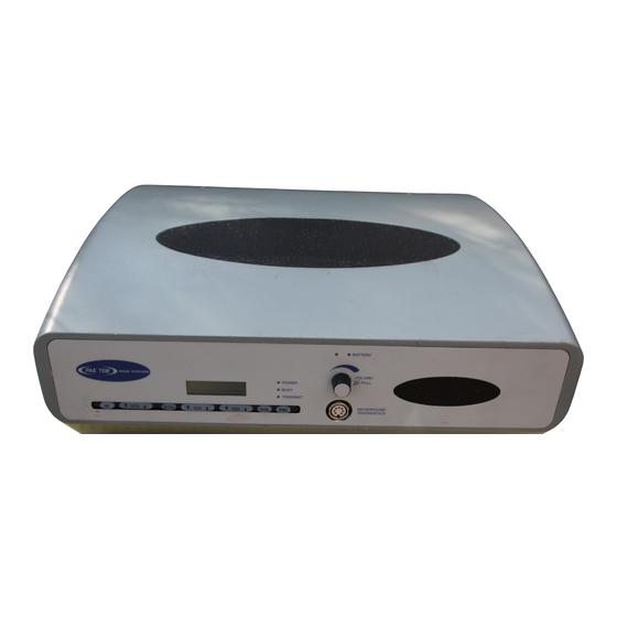
Page 18: Front Panel Controls
When the battery is charged to approximately 75% of its maximum, the indicator changes to green. Loudspeaker Grille (Figure 3, Item 9). The base station's internal loudspeaker is fitted behind this grille. T6M Base Station User Guide Page 18... -
Page 19: Pri Button
Neither the Power button, nor the rear panel Power switch, isolates the input supply from the equipment. Lethal voltages are still present in the base station's internal power supply. To ensure safe working during maintenance, the ac and dc input supplies must be disconnected from the base station. T6M Base Station User Guide Page 19... -
Page 20: Switching On And Off
If this is not done, when next switched on the base station may revert to previous channel and mode settings, and not those that were active immediately before switching off. Base Station Front Panel Power Button Location T6M Base Station User Guide Page 20... -
Page 21: Operating The Base Station In Normal Mode
These operating procedures assume the fist microphone that is normally supplied with the base station is being used. As an alternative to the fist microphone, a microphone/headset can be used. T6M Base Station User Guide Page 21... - Page 22 After the required setting is selected, press no more buttons and check that after a few seconds the display changes to show the currently selected channel frequency. The squelch facility is now set. T6M Base Station User Guide Page 22...
-
Page 23: Operating The Base Station In Priority Mode
If the squelch facility requires adjusting, use the procedure ‘Switching and Adjusting the Squelch Facility’ given on page 21. T6M Base Station User Guide Page 23... -
Page 24: Operating The Base Station In Scan Mode
If the squelch facility requires adjusting, use the procedure ‘Switching and Adjusting the Squelch Facility’ given on page 21. T6M Base Station User Guide Page 24... -
Page 25: Programmable Options
Key Beeps This option, when programmed, produces a single beep whenever a button is pressed on the radio's front panel. The volume of the beep is the same as the Warning beep. T6M Base Station User Guide Page 25... -
Page 26: Transmit Inhibit
118.0000 MHz to 118.1916 MHz. The pattern is the same for any frequency within the radio's frequency range. The display conforms to ICAO convention for 8.33 kHz operation. Note that operation using 8.33 kHz channel spacing within the USA is not currently allowed under FCC regulations. T6M Base Station User Guide Page 26... - Page 27 8.33 kHz 118.160 MHz 118.1666 MHz 8.33 kHz 118.165 MHz 118.1750 MHz 25 kHz 118.175 MHz 118.1750 MHz 8.33 kHz 118.180 MHz 118.1833 MHz 8.33 kHz 118.185 MHz 118.1916 MHz 8.33 kHz 118.190 MHz T6M Base Station User Guide Page 27...
-
Page 28: Fault And Error Codes
This error is displayed when the base station is initially switched on and no personality information, or corrupted personality information, is detected. Refer cErr Critical error to ‘Programming the Base Station’ on page 37 and load a personality into the base station. T6M Base Station User Guide Page 28... -
Page 29: Chapter 4 - Installation
Chapter 4 - Installation The instructions in this chapter should be followed, in the order given, to install the T6M base station. INTRODUCTION Warning. Lethal Voltages! The instructions given in this chapter involve connecting lethal voltages to the equipment. The instructions, therefore, must be carried out only by suitably qualified personnel. -
Page 30: Unpacking
PCB. Refer to Figure 11 and identify links JP1 and JP2. Ensure the two links are set to the required positions. Slide the equipment back into its enclosure. Refit the six M4 securing screws and washers. T6M Base Station User Guide Page 30... -
Page 31: Siting The Base Station
CONNECTING A T6M CONTROLLER TO THE BASE STATION Up to four T6M Controllers can be connected to a base station. Users should refer to the T6M Controller User Guide (part number 31-3600T6MC) for installation details. -
Page 32: Connecting A Microphone
400 mm to 1200 mm. Two screws secure the bracket to the chosen surface. The actual bracket should be used as a template for drilling the two screw holes. T6M Base Station User Guide Page 32... -
Page 33: Connecting External Facilities
Table 6. A 15-way D-type plug (Table 3, item 4) is provided to make the facilities connections. Connection to the plug should be made using screened cable; the braid should be connected to the plug's shell as shown in the illustration on page 35. T6M Base Station User Guide Page 33... - Page 34 Control Desk PTT - internally connected to 0 V. Not connected Not connected Not connected When this line is connected to 0 V, the base station External Tx inhibit Input cannot be keyed. Ground 0 V. T6M Base Station User Guide Page 34...
-
Page 35: Connecting A Dc Input Supply
The DC Input connector fitted to the rear panel (see following illustration) is used for this supply. Connection should be made using a free XLR socket; for example, PAE part number 20-01030106. DC Input Connector T6M Base Station User Guide Page 35... -
Page 36: Connecting An Ac Input Supply
3). The free end of the cable should be terminated with a connector suitable for the local mains supply. The T6M base station is a class 1 equipment. The ac supply cable must have a green-and-yellow protective earthing conductor electrically connected to the protective earthing terminal of the equipment connector, and the supply output connector. -
Page 37: Chapter 5 - Programming The Base Station
Saving a personality (see page 44). Opening a saved personality (see page 45). Loading a personality into the radio (see page 45). Reading a personality from the radio (see page 45). Printing a personality report (see page 46). T6M Base Station User Guide Page 37... - Page 38 16 character Identification A free format text string that describes the channel alphanumeric Empty string string frequency. string Enabled or Must be enabled for correct operation of the base Base Disabled disabled station. T6M Base Station User Guide Page 38...
-
Page 39: Programmable Options
Key Beeps This option, when enabled, produces a single beep whenever a button is pressed on the radio's front panel. The volume of the beep is the same as the Warning beep. T6M Base Station User Guide Page 39... -
Page 40: Hold On Scan Mode
41) is displayed. If the Frequencies page is displayed, select the General tab. From the menu-bar select File then New. This action resets all options to the default value and clears all entries, except one, in the frequency table. T6M Base Station User Guide Page 40... - Page 41 If the Use Channel Strings facility is selected, the maximum number of channel frequencies that can be stored is reduced from 760 to 400. Descriptive text is shown on the frequency list within this programme; it is not displayed at the radio. T6M Base Station User Guide Page 41...
- Page 42 46 characters). (16) When all fields on the General page are correctly configured, use the mouse and click on the Frequencies tab. Check that the Frequencies page is shown (see next page). T6M Base Station User Guide Page 42...
- Page 43 Delete channel box. When all the required frequency channels have been entered, click on the ‘Verify and sort the table’ box. Any errors made when compiling the frequencies page are automatically identified to the user. T6M Base Station User Guide Page 43...
-
Page 44: Saving A Personality
If errors do exist they are highlighted to the user. If the save is successful, the file name appears at the top of the programming window. At any time, the personality can be edited and saved using the same filename. T6M Base Station User Guide Page 44... -
Page 45: Opening A Saved Personality
The progress of the read operation is displayed on the status line at the bottom of the programming screen. When complete, switch off the radio and laptop, remove the programming lead, reconnect the radio's microphone and restore the equipment ready for operational use. T6M Base Station User Guide Page 45... -
Page 46: Printing A Personality Report
When Notepad displays the personality it can be saved as a text file, or printed. Previously saved Notepad files containing personalities can be retrieved by selecting Report, then Open from the menu-bar. T6M Base Station User Guide Page 46... -
Page 47: Chapter 6 - Spares
04F05509034 Fuse 5 A anti-surge, 20 mm (located in ac connector) 29F01140102S Fuse 15 A, size 0 (dc input) 29-01350201 Microphone 24-11030301 Optional battery 06F30012300 Programming kit (includes CD-ROM and programming lead) 70-T6MPMKIT T6M Base Station User Guide Page 47... - Page 48 Intentionally Blank T6M Base Station User Guide Page 48...
-
Page 49: Chapter 7 - Maintenance
Chapter 7 - Maintenance This chapter details the scheduled maintenance required by the T6M base station. It also provides fault finding guidance. SCHEDULED MAINTENANCE Scheduled maintenance to the T6M base station involves the following checks: Transmit power and frequency accuracy test. This check should be carried out annually. -
Page 50: Transmit Power And Frequency Accuracy Test
Power button. Without releasing the Power button, press and release the SQL button, then the SCN button, and finally the PRI button. Release the Power button. Base Station Front Panel Power Button Location T6M Base Station User Guide Page 50... - Page 51 Key the transmitter and check that the wattmeter reads between 6 and 12 watts. Check that the frequency counter reads between 136.974745 and 136.975205 MHz. (18) On completion, switch off the base station and disconnect the test equipment. Restore the base station ready for operational use. T6M Base Station User Guide Page 51...
-
Page 52: Receiver Sensitivity Check
An optional battery can be fitted to act as a backup supply if the mains supply fails. The lead acid battery is fitted in the position shown in Figure 8. The battery should be replaced after a period of time that depends on usage. Table 10 details the replacement period according to usage. T6M Base Station User Guide Page 52... -
Page 53: Fault Finding
The T6M base station contains the following replaceable modules (see Figures 6, 7, and 8): A T6M radio module (a self-contained transceiver). - Page 54 CN7 pins 13 and 14. Using Figures 6 and 7 should enable the fault to be diagnosed to either the radio module, or the Interface PCB. If the ‘Receiver Sensitivity Check’ is OK, the fault is probably in the antenna system. T6M Base Station User Guide Page 54...
-
Page 55: Replacing Modules
Slide the equipment out of the enclosure. Note that when fitting a new Interface module, two links must be correctly set. Refer to ‘Setting Internal Links’ on page 30. T6M Base Station User Guide Page 55... - Page 56 Intentionally Blank T6M Base Station User Guide Page 56...
-
Page 57: Chapter 8 - Figures
Base station block diagram Base station interconnection diagram Base station layout diagram Radio module and PSU removal Interface PCB and reservoir capacitor removal Interface PCB layout diagram Cable termination at the N-type connector T6M Base Station User Guide Page 57... - Page 58 Intentionally Blank T6M Base Station User Guide Page 58...
- Page 59 Front and Rear Layout Figure 1 BT6MBS-01...
- Page 60 Rack Mounted Version Figure 2 BT6MBS-13...
- Page 61 For description of controls, see text in chapter 3. Key to Front Panel Controls GA10642 Iss. 1 Figure 3...
- Page 62 External Connection Diagram Figure 4 BT6MBS-11...
- Page 63 Enclosure Securing Detail Figure 5 BT6MBS-10...
- Page 64 Base Station Block Diagram GA10547 Iss. 3 Figure 6...
- Page 65 Base Station Interconnection Diagram GA10548 Iss. 3 Figure 7...
- Page 66 Base Station Layout Diagram GA10719 Iss. 1 Figure 8...
- Page 67 Radio Module Power Supply Unit (PSU) Radio Module and PSU Removal GA10721 Iss. 1 (radio) and GA10731 Iss. 1 (PSU) Figure 9...
- Page 68 Reservoir Capacitor Interface PCB Interface PCB and Reservoir Capacitor Removal GA10732 Iss. 1 and GA10720 Iss. 1 Figure 10...
- Page 69 Interface PCB Layout Diagram GA10751 Iss 1 Figure 11...
- Page 70 Cable Termination at the N-Type Connector Figure 12 BT6MBS-12-1...
Need help?
Do you have a question about the T6M and is the answer not in the manual?
Questions and answers