
Related Manuals for Rohde & Schwarz CMU 300


Summary of Contents for Rohde & Schwarz CMU 300
- Page 1 Test and Measurement Division Operating Manual Universal Radio Communication Tester R&S CMU 200 / CMU 300 1100.0008.02/1100.0008.53/1100.0008.03 Printed in the Federal Republic of Germany 1100.4903.12-10-...
- Page 2 Dear Customer, throughout this manual, CMU200 and CMU300 is generally used as an abbreviation for the Universal Radio Communication Testers R&S CMU 200 and R&S CMU 300.
- Page 3 Universal Radio Communication Tester R&S CMU 200, stock no. 1100.0008.53, only for Bluetooth™ device tests. • Universal Radio Communication Tester R&S CMU 300, stock no. 1100.0008.03, for base station tests. Instructions for Unpacking the Instrument ! Take the instrument out of the shipping box and check whether the items listed in the packing list above are all included.
- Page 5 Tabbed Divider Overview Tabbed Divider Overview List of Figures and Tables Data Sheet Safety Instructions Certificate of Quality EU Certificate of Conformity List of R&S Representatives Manuals for Universal Radio Communication Tester CMU Tabbed Divider Chapter 1: Putting into Operation Chapter 2: Getting Started Chapter 3:...
-
Page 7: Table Of Contents
Figures Figures Fig. 1-1 CMU front view ........................1.1 Fig. 1-2 CMU front view – hardkeys ....................1.2 Fig. 1-3 CMU front view – hardkeys ....................1.3 Fig. 1-4 CMU front view – hardkeys ....................1.4 Fig. 1-5 CMU front view connectors ....................1.5 Fig. 1-6 CMU front view–... - Page 8 Figures Fig. 4-31 Connection Control – RF connectors ................. 4.64 Fig. 4-32 Connection Control – Synchronization ................4.67 Fig. 4-33 Measurement menu Analyzer/Generator (Audio) .............. 4.75 Fig. 4-34 Display of test settings and measurement results (Audio) ..........4.77 Fig. 4-35 Analyzer Configuration – Control ..................4.79 Fig.
- Page 9 Tables Tables Table 1-1 Software installation with the VersionManager ..............1.20 Table 3-1 Operation of popup menus ....................3.9 Table 3-2 Assignment of numerical keys and alphanumeric characters..........3.12 Table 3-3 Operation of select fields ....................3.14 Table 3-4 Measurements in function group RF (Non Signalling) ............3.17 Table 3-5 Measurements in function group Audio (with option CMU-B41) ........
-
Page 11: Technical Information
Universal Radio Communication Tester R&S CMU200 Option R&S CMU-B17 IQ AND IF INTERFACE Technical Information The R&S CMU200 in combination with the option R&S CMU-B17 represents an unique solution to get access to different IF- and IQ – signals on up- / down-link signal paths of mobile communication systems. -
Page 12: Block Diagram
R&S Technical Information R&S CMU-B17 Contents BLOCK DIAGRAM ............................ 2 FUNCTIONALITY............................3 APPLICATIONS ............................6 ORDERING INFORMATION........................8 ANNEX 1: SIGNAL PATHS R&S CMU200 INCL. R&S CMU-B17 ............9 ANNEX 2: ASSIGNMENT OF IQ / IF CONNECTORS ON R&S CMU REAR PANEL......10 ANNEX 3: LOCATION OF R&S CMU-B17 CONNECTORS ON REAR PANEL ........ -
Page 13: Functionality
R&S CMU-B17 Technical Specification Functionality Default: Bypass mode for highest measurement accuracy / RF tests Setting: RX/TX Bypass IEEE commands: CONFigure:IQIF:RXTXcombined[?] BYP CONFigure:IQIF:RXPath[?] BYP CONFigure:IQIF:TXPath[?] BYP Functionality: • No influence to transmitted and received signals. • The path loss due to the inserted R&S CMU-B17 board will be considered automatically during mandatory calibration procedure on R&S ACS calibration... - Page 14 Technical Specification R&S CMU-B17 Interruption of IQ / IF signal paths for external signal processing Predefined paths Setting: Fading Path IEEE commands: CONFigure:IQIF:RXTXcombined[?] FPAT CONFigure:IQIF:RXPath[?] BYP CONFigure:IQIF:TXPath[?] XOIO Functionality: • The setting “Fading Path” can be used for connecting an external baseband fading simulator (pls.
- Page 15 R&S CMU-B17 Technical Specification Setting: IF IN/OUT IEEE commands: CONFigure:IQIF:RXTXcombined[?] IOXO CONFigure:IQIF:RXPath[?] IOXO CONFigure:IQIF:TXPath[?] IOXO User definable signal paths Setting: user defined IEEE commands: CONFigure:IQIF:RXPath[?] BYIQ CONFigure:IQIF:TXPath[?] BYP Functionality: It is possible to select different user specific IQ / IF paths depending on application. 1100.4903.12 TI.5...
-
Page 16: Applications
Technical Specification R&S CMU-B17 Applications Bit Error Rate measurements on digital receivers under fading conditions R&S CMU in combination with R&S SMIQ (R&S SMIQ provides the faded RF signal) R&S CMU200 setting: Fading Path or Bypass w. I/Q IF OUT^ CMU200 CMU-B17 Signal-... - Page 17 R&S CMU-B17 Technical Specification R&S CMU in combination with fading simulator R&S ABFS or R&S SMIQ/SMIQB14 (R&S CMU provides the faded RF signal) R&S CMU200 setting: Fading Path CMU200 RF configuration CMU-B17 Signal- incl. generation level setting IQ In IQ Out Fading Simulator ABFS or SMIQ/SMIQB14...
-
Page 18: Ordering Information
Technical Specification R&S CMU-B17 R&S CMU200 as RF generator / IQ analyzer If IQ signals are applied to the receive section of the tester, signal analysis can be performed in the same manner as when feeding a RF signal. In this connection, modulation analysis, for example, is useful since it evaluates the quality of an IQ signal. -
Page 19: Annex 1: Signal Paths R&S Cmu200 Incl. R&S Cmu-B17
R&S CMU-B17 Technical Specification Annex 1: Signal paths R&S CMU200 incl. R&S CMU-B17 RF4 IN RF3 OUT CMU Front Panel Frontend / RF switching unit for level adaptation and selection of connector RX / TX board for transformation RF / IF and vice versa RX path TX path... -
Page 20: Annex 2: Assignment Of Iq / If Connectors On R&S Cmu Rear Panel
Technical Specification R&S CMU-B17 Annex 2: Assignment of IQ / IF connectors on R&S CMU rear panel Sub-D connector I/Q CH1: Signal designation Function MOD_ I_ IN I input, TX path, max ±0.5 V, impedance 50 Ohm MOD_Q_IN Q input, TX path, max ±0.5 V, impedance 50 Ohm MOD_I_OUT I output, TX path,... -
Page 21: Annex 3: Location Of R&S Cmu-B17 Connectors On Rear Panel
R&S CMU-B17 Technical Specification Annex 3: Location of R&S CMU-B17 connectors on rear panel 1100.4903.12 TI.11... -
Page 22: Annex 4: Specification
Technical Specification R&S CMU-B17 Annex 4: Specification IQ Interface Analogue IQ Outputs (IF->IQ; TX- and RX-Paths, analogue I/Q Output) (Connector I/Q CH1) IQ Bandwidth 0 to 2.5 MHz Max output voltage range -1 V to +1 V, peak =1V, peak 50 Ω... - Page 23 R&S CMU-B17 Technical Specification Influence on RF interface WCDMA Measurements (3GPP FDD, UE test) Additional influence on analogue I/Q Input and Output considered; for signal quality TX- and RX-Paths <5 %, rms GSM / EDGE Measurements Additional influence on Analogue I/Q Input and Output considered; for signal quality, EVM TX- and RX-Paths;...
- Page 24 Technical Specification R&S CMU-B17 IF Outputs, RX Path (Connector IF3 RX CH1 OUT) IF level range up to +4 dBm, PEP Standard IF frequencies RF/GSM/IS136/AMPS/IS95/CDMA2000 10.7 MHz WCDMA 7.68 MHz Aspects to be considered, if TX or RX signal paths are interrupted *: The RF frequency of the R&S CMU influences the rotating direction of the IQ vector.
- Page 25 EC Certificate of Conformity Certificate No.: 99035, page 1 This is to certify that: Equipment type Stock No. Designation CMU200 1100.0008.02/.53 Universal Radio Communication Tester CMU300 1100.0008.03 complies with the provisions of the Directive of the Council of the European Union on the approximation of the laws of the Member States - relating to electrical equipment for use within defined voltage limits (73/23/EEC revised by 93/68/EEC)
- Page 26 EC Certificate of Conformity Certificate No.: 99035, page 2 This is to certify that: Equipment type Stock No. Designation CMU-B11 1100.5000.02 Reference Oscillator CMU-B12 1100.5100.02 Reference Oscillator CMU-B15 1100.6006.02 Additional RF und IF Connections CMU-B17 1100.6906.02 IQ and IF Interfaces CMU-B21 1100.5200.02 Versatile Signalling Unit...
- Page 27 EC Certificate of Conformity Certificate No.: 99035, page 3 This is to certify that: Equipment type Stock No. Designation CMU-B81 1100.6506.02 CDMA(IS95) Signalling Unit CMU-B82 1150.0201.02/.04 ACCESS Board für CDMA Signalling Unit CMU-B83 1150.0301.02/.04 CDMA2000 Signalling Unit 1150.0301.12/.14 CMU-B85 1100.7002.02/.04 Speech Codec for CDMA2000 CMU-B87 1150.2404.02/.04...
- Page 29 Certified Quality System Certified Environmental System ISO 9001 ISO 14001 DQS REG. NO 1954 QM DQS REG. NO 1954 UM Qualitätszertifikat Certificate of quality Certificat de qualité Sehr geehrter Kunde, Dear Customer, Cher client, Sie haben sich für den Kauf eines Rohde & You have decided to buy a Rohde &...
- Page 31 Support Center Telefon / Telephone: +49 (0)180 512 42 42 Fax: +49 89 41 29 137 77 E-mail: CustomerSupport@rohde-schwarz.com Für technische Fragen zu diesem Rohde & Schwarz-Gerät steht Ihnen die Hotline der Rohde & Schwarz Vertriebs-GmbH, Support Center, zur Verfügung. Unser Team bespricht mit Ihnen Ihre Fragen und sucht Lösungen für Ihre Probleme.
- Page 33 Adressen/Addresses FIRMENSITZ/HEADQUARTERS Phone Zweigniederlassung Süd, Geschäftsstelle +49 (89) 41 86 95-0 München +49 (89) 40 47 64 E-mail Mühldorfstraße 15 · D-81671 München Postfach 80 14 69 · D-81614 München Rohde & Schwarz GmbH & Co. KG +49 (89) 41 29-0 Mühldorfstraße 15 ·...
- Page 34 Adressen/Addresses Canada ROHDE & SCHWARZ CANADA Inc. +1 (613) 592 80 00 Denmark ROHDE & SCHWARZ DANMARK A/S +45 (43) 43 66 99 555 March Rd. +1 (613) 592 80 09 Ejby Industrivej 40 +45 (43) 43 77 44 Kanata, Ontario K2K 2M5 cgirwarnauth@rscanada.ca 2600 Glostrup Canada...
- Page 35 Adressen/Addresses India ROHDE & SCHWARZ India Pvt. Ltd. +91 (80) 535 23 62 Kenya Excel Enterprises Ltd +254 (2) 55 80 88 Bangalore Office +91 (80) 535 03 61 Dunga Road +254 (2) 54 46 79 No. 24, Service Road, Domlur rsindiab@rsnl.net P.O.Box 42 788 2nd Stage Extension...
- Page 36 Adressen/Addresses Norway ROHDE & SCHWARZ NORGE AS +47 (23) 38 66 00 Sri Lanka LANKA AVIONICS +94 (1) 95 66 78 Enebakkveien 302 B +47 (23) 38 66 01 658/1/1, Negombo Road +94 (1) 95 83 11 1188 Oslo Mattumagala lankavio@sltnet.lk Ragama Oman...
- Page 37 Adressen/Addresses United Arab ROHDE & SCHWARZ Emirates L.L.C. +971 (2) 631 20 40 Emirates P.O.Box 31156 +971 (2) 631 30 40 Abu Dhabi rsuaeam@emirates.net.ae United ROHDE & SCHWARZ UK Ltd. +44 (1252) 81 88 88 (sales) Kingdom Ancells Business Park +44 (1252) 81 88 18 (service) Fleet +44 (1252) 81 14 47...
-
Page 39: Chapter 1: Putting Into Operation
Manuals Contents of Manuals for Universal Radio Communication Tester CMU The user documentation for the R&S CMU 200/300 is divided in this operating manual for the basic instrument (including options CMU-B41, CMU-B17) and separate manuals for individual software and hardware options. The complete documentation is available on CD-ROM, stock no. PD 0757.7746.2x. The latest revisions of all manuals are also posted on the CMU Customer Web on GLORIS. - Page 40 Manuals Service Manual Modules The service manual modules is not delivered with the instrument but may be obtained from your R&S service department using the order number 1100.4903.91. Service manual modules contains information about the individual modules of CMU. This comprises the test and adjustment of the modules, fault detection within the modules and the interface descrip- tion.
- Page 41 Manuals What's new in this Revision... This operating manual describes version V3.40 of the CMU base software including RF and Audio measurements and the IQ-IF interface. Compared to previous versions, this new firmware provides numerous extensions and improvements. The most important new features described in this manual are listed below.
- Page 42 Manuals Frequently Used Abbreviations Att. Attenuation Center Ext. External Freq. Frequency GPIB General Purpose Interface Bus = IEEE Bus according to standard IEC 625.1/IEEE 488.1 Intermediate Frequency Max. Maximum (Level) Peak Resolution Bandwidth Ref. Reference Rel. Relative Radio Frequency Single Side Band Software 1100.4903.12 E-10...
- Page 43 Supplement to the Operating Manual for Universal Radio Communication Tester R&S CMU 200 Addendum to the data sheet, no. 757.4318.25 (1001) With CMU-U99/-B99 installed, the input/output level range and the input/output level uncertainty for RF1 is the same as for RF2. With CMU-U99/-B99 installed, the VSWR of the RF generator and analyzer at RF1 is as follows: VSWR at RF1 connector (RF generator and RF analyzer) page 34...
- Page 45 Contents of Chapter 1 Contents 1 Preparation for Use ..................... 1.1 Front and Rear View.........................1.1 Rear View ............................1.8 Putting the Instrument into Operation ..................1.10 Unpacking the Instrument ..................... 1.10 Setting up the Instrument ...................... 1.10 Mounting in a Rack ....................... 1.11 Connecting the Instrument to the AC Supply................
-
Page 47: Fig. 1-1 Cmu Front View
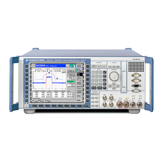
Front and Rear View 1 Preparation for Use This chapter describes the controls and connectors of the Universal Radio Communication Tester CMU and gives all information that is necessary to put the instrument into operation and connect external devices. Notes on reinstallation of the CMU software and a description of the VersionManager termi- nate this chapter. -
Page 48: Fig. 1-2 Cmu Front View - Hardkeys
Front and Rear View Selection of the most important Data input CMU functions via menus 1100.0008.02 FUNCTION SYSTEM Loudspeaker, for MENU future extensions DATA CTRL HELP SETUP PRINT SELECT DATA VARIATION DATA 1 M/µ µV PCMCIA interface DATA 2 dBµV as an alternative: Floppy disk drive AUX 3... -
Page 49: Fig. 1-3 Cmu Front View - Hardkeys
Front and Rear View System control Variation of numeric values and group selection in popup menus 1100.0008.02 FUNCTION SYSTEM MENU DATA CTRL SELECT HELP SETUP PRINT DATA VARIATION DATA 1 M/µ µV DATA 2 dBµV AUX 3 Ω _ µ mark symb ON / OFF... -
Page 50: Fig. 1-4 Cmu Front View - Hardkeys
Front and Rear View 1100.0008.02 FUNCTION SYSTEM MENU DATA CTRL HELP SETUP PRINT SELECT DATA VARIATION DATA 1 M/µ µV DATA 2 dBµV AUX 3 Ω _ µ mark symb ON / OFF ENTER UNIT... EXP/CMP CONT/HALT SPEECH Extended editor CONTROL and instrument AUX 1... -
Page 51: Fig. 1-5 Cmu Front View Connectors
Front and Rear View 1100.0008.02 FUNCTION SYSTEM MENU DATA CTRL HELP SETUP PRINT SELECT DATA VARIATION DATA 1 M/µ µV For future extensions DATA 2 dBµV AUX 3 Ω _ µ mark symb Auxiliary input/output AUX3 ON / OFF ENTER UNIT... -
Page 52: Fig. 1-6 Cmu Front View- Connectors
Front and Rear View 1100.0008.02 FUNCTION SYSTEM MENU DATA CTRL HELP SETUP PRINT SELECT VARIATION DATA DATA 1 M/µ µV DATA 2 dBµV AUX 3 Ω _ µ mark symb ON / OFF ENTER UNIT... EXP/CMP CONT/HALT SPEECH CONTROL AUX 1 AUX 2 Bidirectional RF connectors RF4 IN... -
Page 53: Fig. 1-7 Cmu Rear View
Rear View Rear View Synchronization inputs and outputs, IF interface (with option CMU-B17) REF IN REF OUT 1 REF OUT 2 1 00 -24 0 V A C IF 3 RX CH1 3 ,1 -1 ,3 A 5 0-4 00 H z SERVICE IF3 RX CH1 IN IF3 RX CH1 OUT... -
Page 54: Fig. 1-8 Cmu Rear View – Signal Inputs And Outputs
Rear View Inputs and outputs for reference frequency and network-specific clock frequency REF IN REF OUT 1 REF OUT 2 REF IN REF OUT 1 IF 3 RX CH1 Intermediate SERVICE IF3 RX CH1 IN IF3 RX CH1 IN frequency from CMU receiver, AUX4 Auxiliary and... -
Page 55: Fig. 1-9 Cmu Rear View - Abis And I/Q-If Inputs And Outputs
Rear View Input and output for Abis interface (CMU 300 only) Balanced Abis interface (CMU 300 only) REF IN REF OUT 1 REF OUT 2 ABIS RX ABIS TX REF IN REF OUT 1 ABIS IF 3 RX CH1 SERVICE... -
Page 56: Putting The Instrument Into Operation
Putting the Instrument into Operation Putting the Instrument into Operation Caution! Please make sure to follow the instructions of the following sections in order not to cause damage to the instrument or endanger people. This is of particular importance when using the instrument for the first time. Unpacking the Instrument ! Take the instrument out of the shipping box and check whether the items listed in the packing list (see separate yellow sheet after the... -
Page 57: Mounting In A Rack
Putting the Instrument into Operation Mounting in a Rack Using the adapter ZZA-411 (order number 1096.3283.00) the instrument can be mounted in 19" racks according to the mounting instructions supplied with the rack adapter. Note: For convenient operation of the instrument note the following: ! Allow for sufficient air supply in the rack. - Page 58 Putting the Instrument into Operation The ON/STANDBY key activates two different operating modes indicated by colored LEDs: Standby Only the OCXO reference frequency oscillator (Option CMU- B11/B12), if installed, is supplied with operating voltage. The orange LED (STANDBY) on the right is illuminated. Operation In this operating mode, all modules of the instrument are STANDBY supplied with operating voltage.
-
Page 59: Switching Off The Instrument
Putting the Instrument into Operation Switching off the Instrument In order not to lose any settings that have been made, proceed in the following order to switch off the CMU: ! Remove any storage medium from the PCMCIA interface or floppy disk drive. -
Page 60: Connecting The Cmu To The Test Setup
Connecting the CMU to the Test Setup Connecting the CMU to the Test Setup Warning: Connect external devices and peripherals only when the instrument is switched off or in STANDBY mode. Otherwise, future errors cannot be excluded. Connecting a Controller The CMU can be connected to an external controller via the GPIB bus (IEEE bus according to standard IEEE 488;... - Page 61 Connecting the CMU to the Test Setup The CMU can be connected to the serial interface of a controller via one of Connection via serial the serial interfaces COM 1 or COM 2 and a so-called null-modem cable. interface The pin assignment and wiring of a null-modem cable are described in section Handshake of chapter 8.
-
Page 62: Connecting An External Keyboard
Connecting the CMU to the Test Setup Connecting an External Keyboard The 6-contact Mini DIN connector at the rear of the instrument permits to KEYBOARD connect an external PC keyboard (PS/2) to the CMU. An external keyboard facilitates the input of numbers and texts. For the interface description see section "Hardware Interfaces"... -
Page 63: Connecting A Printer
Connecting the CMU to the Test Setup Connecting a Printer A printer can be connected via the 25-contact parallel interface LPT at the rear of the instrument (recommended) or one of the serial interfaces COM 1 or COM 2. For the interface description see section "Hardware Interfaces" in chapter 8. -
Page 64: Fig. 1-9 Versionmanager Main Screen (Example)
Software Update and Version Management Software Update and Version Management Your CMU was delivered with the latest software and firmware version available. New firmware can be easily installed via the floppy disk drive (option CMU-U61) or the PCMCIA interface on the front of the instrument. - Page 65 Software Update and Version Management Each entry in the list corresponds to a firmware configuration consisting of exactly one CMU base software version (top level on the left side) plus a set of associated options (network tests, second level). The version to be activated is displayed in red color on top of the list.
-
Page 66: Table 1-1 Software Installation With The Versionmanager
Software Update and Version Management Activate Activate the current firmware configuration. Install software... opens a list of all firmware installation versions available Install software... on an external storage medium (floppy disk/PCMCIA card). As explained in Table 1-1, this function depends on the type and number of storage media and on the number of installation versions available. - Page 67 Software Update and Version Management Install software... Select the card in slot 0 or slot 1 as an installation medium. If the medium contains several installation versions, the software version selection dialog is called up, see below. Software version The software version selection dialog lists all installation versions on the selection dialog: current medium (floppy, PCMCIA card).
- Page 68 Software Update and Version Management Note: This dialog is skipped if the new base software version is not compatible with any of the existing configurations. An incompatible new base software must be installed as a new base software. Install as new base Create a new configuration based on the base software to be installed.
- Page 69 Software Update and Version Management Back to... Close the current screen and go back to the software version selection dialog to select a compatible software version. Terminating the After successful installation of each software version the CMU displays the software update: following screen: Install next software...
- Page 70 Software Update and Version Management Delete Delete the current version and return back to the previous screen. List software List software opens a list of all available firmware configurations. It is possible to activate and delete configurations from the list; see description of Activate software and Delete software functions above.
- Page 71 Software Update and Version Management Write log files to disk copies all *.log files stored on the CMU hard disk to an Write log files to disk external storage medium (floppy or PCMCIA card). The *.log source files on the hard disk are not deleted. The Write log files to disk function opens a blue message box indicating the storage capacity of the external disk needed.
- Page 72 Software Update and Version Management Escape Close the Info screen and return to the previous screen. Error and notify During operation, the VersionManager can display two different types of message messages: • Error messages indicating that an action could not be successfully performed are displayed in yellow boxes.
-
Page 73: Rf User Correction
RF User Correction RF User Correction The purpose of the RF user correction is to compensate for an inevitable frequency and level- dependent attenuation in the test setup (frequency and level response correction). Level correction values are determined by means of a signal generator or power meter connected to the CMU’s input and output ports and stored to a file, which is transferred to the CMU in order to modify its RF generator level and to correct its RF analyzer results. -
Page 74: Compiling And Loading User Correction Tables
RF User Correction Compiling and Loading User Correction Tables To generate user correction tables and activate the user correction proceed as follows: To deactivate old user 1. Start the CMU and press the Menu Select key after the boot-up correction (if available)… sequence is terminated (from the moment when the CMU display turns black until the end of the 3-beep acoustic signal) to activate the VersionManager. - Page 75 RF User Correction To acquire the input 9. Apply the RF output signal of an external signal generator to one of correction values… the RF input connectors RF1, RF2, or RF4 IN of the CMU using the test setup (cables, power splitters, antenna coupler…) that will be used for the corrected measurements.
-
Page 76: File Format For User Correction Tables
RF User Correction File Format for User Correction Tables The user correction file is an ASCII file named USERCOR1.DAT that is stored in the directory C:\INTERNAL\USERCOR\ on the internal hard disk of the CMU. The file contains up to 6 independent tables to store the correction values for the 3 RF output connectors and the 3 RF input connectors of the instrument. -
Page 77: Interpolation Rules
RF User Correction Level of the measured or generated signal in dBm, to be arranged in Level points descending order, starting in row 2 (highest level). The level points must be positive or negative integer numbers, followed by a colon, and can be distributed across the entire RF input and output power range of the connectors (see data sheet). -
Page 79: Chapter 2: Getting Started
Contents of Chapter 2 Contents 2 Getting Started ..................... A Short Tutorial on CMU Operation ....................2.1 Condensed Operating Instructions ..................2.1 How to access and close menus .....................2.2 How to use dialog elements in the menus ................2.3 Startup of the CMU...........................2.4 RF Non Signalling Measurements ....................2.8 1100.4903.12... -
Page 81: Getting Started
A Short Tutorial on CMU Operation 2 Getting Started The following Chapter presents a sample session with the universal radio communication tester CMU. It is intended to provide a quick overview of the settings provided in the base system and the RF function group. -
Page 82: How To Access And Close Menus
A Short Tutorial on CMU Operation How to access and close menus A startup menu is displayed automatically when the CMU is switched Some general configuration and selection menus can be opened via SETUP the MENU SELECT, RESET, INFO, PRINT, HELP or SETUP keys on the front panel. -
Page 83: How To Use Dialog Elements In The Menus
A Short Tutorial on CMU Operation How to use dialog elements in the menus The dialog elements assigned to a softkey are selected by pressing the softkey. Different input fields can be selected by means of the 4 cursor keys (blue frame shows active input field). -
Page 84: Startup Of The Cmu
Startup of the CMU Startup of the CMU This Chapter describes how to customize the CMU and perform simple RF measurements. As a pre- requisite for starting the session, the instrument must be correctly set up and connected to the AC power supply as described in Chapter 1. - Page 85 Startup of the CMU Additional Information... Alternative Settings and Measurements ... on Step 1 " & Mains switch on the rear panel Chapter 1 When the mains switch at the rear is set to the O position, the The CMU is automatically set to complete instrument is disconnected from the power supply.
- Page 86 Startup of the CMU Step 4 ! Press the SETUP key to access general SETUP device settings. Press the Time hotkey to switch over to " the Time tab of the Setup menu. Step 5 The Time tab of the Setup menu displays the current time zone, time and date.
- Page 87 Startup of the CMU Additional Information... Alternative Settings and Measurements ... on Step 4 " Softkeys and hotkeys & Chapter 3 Softkeys and hotkeys are activated by pressing the associ- ated keys on both sides and across the bottom of the display. The general purpose of softkeys is to provide settings, con- trol the generator and the measurements.
-
Page 88: Rf Non Signalling Measurements
RF Non Signalling Measurements RF Non Signalling Measurements In the RF Non Signalling mode, a continuous or pulsed RF signal can be generated and a RF signal with definite frequency characteristics can be analyzed. The signal level can be plotted in oscillographi- cal (Power) or spectral (Spectrum) representation. - Page 89 RF Non Signalling Measurements Additional Information... Alternative Settings and Measurements ... on Step 1 " & Menu Select menu Chapter 4 The Menu Select menu shows all function groups installed on For digital network tests refer to your CMU. If a function group is selected the available test the relevant operating manuals.
- Page 90 RF Non Signalling Measurements Step 3 ! Press the Connect. Control softkey and use the Generator hotkey to open the " Generator tab. The Generator tab controls the RF genera- tor and defines the Frequency and Modula- tion of the generated RF signal. ! Select the Generator softkey by press- ing once.
- Page 91 RF Non Signalling Measurements Additional Information... Alternative Settings and Measurements ... on Step 3 " & RF connectors Chapter 4 The RF Connection Control menu configures the input and Settings made in the Connect. output connectors in the RF function group. The four connec- Control menus apply to the entire tors on the front panel differ by their permissible range of in- function group RF Non Signalling.
- Page 92 RF Non Signalling Measurements Step 4 ! Press the Power hotkey to switch over to the graphical menu Power. The Power menu shows the RF signal power measured as a function of time at a particular frequency and resolution band- width.
- Page 93 RF Non Signalling Measurements Additional Information... Alternative Settings and Measurements ... on Step 4 " & Trigger mode Chapter 4 The trigger mode is set in the Analyzer tab of the Connection The Frequency softkey defines Control menu or via the Trigger softkey in the graphical the frequency of the measured measurement menus.
- Page 95 Contents of Chapter 3 Contents 3 Manual Operation....................Controls.............................3.1 Rotary Knob ..........................3.2 Front Panel Keys........................3.2 Softkeys............................3.2 Hotkeys ............................3.3 Operating Menus ..........................3.4 Measurement Menus .......................3.4 Graphical Measurement Menus....................3.7 Popup Menus ...........................3.8 Operation of Popup Menus....................3.9 Dialog Elements in the Menu ....................... 3.10 Input Fields..........................
-
Page 97: Manual Operation
Controls 3 Manual Operation This chapter provides a survey of the CMU's operating concept. This includes a description of the basic menu types, the selection and setting of parameters, and a general discussion of measurement control. The operating menus in the CMU basic system, the RF function group, and optional function groups are presented in an overview at the end of this chapter and described in greater detail in Chapter 4. -
Page 98: Rotary Knob
Controls Rotary Knob The rotary knob (spinwheel) can be used in two different ways: • It is turned to select entries in list fields and tables and to vary (increment/decrement) numerical and alphanumerical entries. • It is pressed to expand or compress table sections (thus replacing the ON/OFF key), to expand pull-down lists, to open auxiliary input fields, and to confirm numerical entries or selections (thus replacing the ENTER key). -
Page 99: Hotkeys
Controls − The softkey is a measurement control softkey (main softkey) indicating the measurement state (RUN, OFF, HLT). A yellow triangle indicates that a popup menu providing configurations can be opened with the softkey (press once for selection, a second time for opening the popup). A measurement can be started and aborted with the ON/OFF key (i.e. -
Page 100: Fig. 3-2 Example Of A Measurement Menu
Operating Menus Operating Menus The CMU offers a large variety of operating modes and applications. To ensure quick and easy operation, uniform menus have been implemented. They can be divided into three types: Measurement menu Offers the most important settings controlling a measurement and displays the main results. - Page 101 Operating Menus • The function group is indicated to the left of the operating mode: RF measurements Audio Analyzer and Generator (with option CMU-B41) In network test applications, the signalling states that are specific to the applications are indicated. The corresponding icons are discussed in the relevant manuals (see GSMxxx-MS etc.).
- Page 102 Operating Menus Softkeys for important settings The softkeys below the measurement control softkey provide groups of important measurement settings. Each softkey activates an associated hotkey bar. An active softkey is displayed in inverse video. The Menus softkey displays all measurements in the function group, so it is possible to change from one measurement to another.
-
Page 103: Fig. 3-3 Example Of Graphical Measurement Menu
Operating Menus Graphical Measurement Menus The CMU displays arrays of measurement results in the form of two-dimensional diagrams. In order to obtain additional space for the test diagram, no settings table is displayed. The header and the functionality of the softkeys and associated hotkeys is identical to the measurement menu; see section Measurement Menus on page 3.4. -
Page 104: Fig. 3-4 Example Of A Popup Menu
Operating Menus Popup Menus Popup menus extend the functionality of a measurement menu. They are assigned to the configuration softkey Connect. Control as well as to all measurement control softkeys in a measurement menu that are marked by a yellow triangle at the bottom right. They may be divided into several tabs that are selected via hotkeys in the measurement menu. -
Page 105: Table 3-1 Operation Of Popup Menus
Operating Menus Operation of Popup Menus The following table provides an overview of the operation of popup menus. Table 3-1 Operation of popup menus Action Operation via keys Open menu Press the softkey twice (selection plus opening of menu), press only once in the case of Connect. -
Page 106: Dialog Elements In The Menu
Dialog Elements in the Menu Dialog Elements in the Menu This section describes the various types of dialog fields and the procedure for the input of values and parameters. In many input or select field types, a selection made must be confirmed using the ENTER key. The cursor can be freely shifted over these fields;... - Page 107 Dialog Elements in the Menu digit to be incremented by 1. The editor behaves analogously when a “0“ is decremented. An Enter symbol at the bottom right of the input field indicates that the current value has yet to be written to the CMU software.
-
Page 108: Input Of Alphanumerical Characters
Dialog Elements in the Menu Error message during input If the value defined in the input field is too high or too low, a window with the error message „<numerical value> is out of range. <permissible maximum value> is limit.“ will appear together with three buttons: Accept Permissible maximum value accepted for input... - Page 109 Dialog Elements in the Menu The most important possible inputs using the rotary knob or the digital keys are described in the following. Activating the input field and auxiliary editor % To activate the input field press the associated softkey. If the softkey is assigned to a panel with several controls, use the cursor key to select the desired input field.
-
Page 110: Select Fields In Popup Menus
Dialog Elements in the Menu In insert mode, the cursor appears in the input field. % Use the (backspace) key to delete the character to the left of the cursor. % Use the (delete) key to delete the inversely displayed character (in overwrite mode). - Page 111 Dialog Elements in the Menu List fields (selection 1 out of n) provide a choice of several text lines in a rectangular window: % Select one out of several list fields using the cursor keys. % To select a line use the rotary knob. If a line beyond the edge of the list is to be selected, the whole list will be shifted (scroll function).
-
Page 112: Measurement Control
Measurement Control Measurement Control This section gives a brief survey of the CMU’s measurement control using the function group RF Non Signalling as an example. This includes a discussion of the different measurement modes and measured quantities. Settings and measurement parameters frequently encountered are explained from a general point of view. -
Page 113: Table 3-4 Measurements In Function Group Rf (Non Signalling)
Measurement Control A Configuration popup menu offering specific settings is assigned to most Configuration measurement groups (see e.g. the Power and Spectrum measurements in the of measurements RF function group and the Multitone measurement in the Audio function group). The Configuration menu also provides general parameters that can be defined independently in many measurement groups: •... -
Page 114: General Settings
Measurement Control Table 3-5 Measurements in function group Audio (with option CMU-B41) Menu Function Analyzer/Generator Generates a single-tone sinusoidal audio signal and measures the DC and AC voltage and the Total Harmonic Distortion and Noise of a single-tone audio signal. Multitone Generates a composite audio signal consisting of up to 20 individual fixed-frequency tones with configurable frequency and level. - Page 115 Measurement Control Counting Repeated single shot measurement with a fixed number of statistics cycles The repetition mode is set in the Control tab of the measurement configuration popup-menus. Note: In contrast to other instrument settings, the repetition modes in manual and remote control are independent and do not overwrite each other.
- Page 116 ≤ Single shot measurement or continuous measurement during the first statistics cycle: At each test point, Average trace no. n is calculated from Average trace no. n – 1 and Current trace no. n according to the following recurrence: − −...
- Page 117 Contents of Chapter 4 Contents 4 Functions and their Application ................ 4.1 Startup Menu.............................4.1 On-Screen Help (HELP Key)......................4.2 Reset of Instrument Settings (RESET Key) ...................4.3 Print Menu (PRINT Menu) ........................4.4 Menu Select............................4.6 Popup Menu Setup...........................4.9 Printer Settings (Setup – Print) ....................4.9 Remote-control Settings (Setup –...
- Page 118 Contents of Chapter 4 Measurement Menu (Spectrum) ................. 4.48 Test settings....................4.49 Measurement Results ..................4.53 Measurement Configurations (Spectrum Configuration) ..........4.54 Connection Control ....................... 4.57 Analyzer Settings (Connection Control – Analyzer) ........... 4.57 Softkey-Oriented Version................4.57 Table-Oriented Version.................. 4.58 Generator Settings (Connection Control –...
-
Page 119: Fig. 4-1 Startup Menu
Startup Menu Functions and their Application This chapter explains in detail all functions of the CMU and their application. The structure of the chapter is based on the menu groups and their function. It is organized like a typical measurement session including the following stages: 1. -
Page 120: Fig. 4-2 Popup Window Help
On-Screen Help (HELP Key) The display windows of the startup menu provide information on Displays in the startup menu • The startup procedure (Process) • Instrument model, serial number and version of the CMU base software (Info). • Installed hardware and software options and equipment (Options). Available software options are listed with their version numbers. -
Page 121: Fig. 4-3 Popup Window Reset
Reset of Instrument Settings (RESET Key) Reset of Instrument Settings (RESET Key) The popup window Reset sets the instrument settings in all or some function groups and test modes to their default values. It is opened via the RESET key (CONTROL keypad). Note: A reset of the instrument does not necessarily mean that the current instrument settings are lost. -
Page 122: Fig. 4-4 Popup Window Print
Print Menu (PRINT Menu) The Reset button resets all settings in the selected function groups and test modes. Reset A box pops up to confirm the reset. While the reset is performed, the message Reset in progress is displayed. All running measurements are aborted and a connection to a DUT is dropped. - Page 123 Print Menu (PRINT Menu) The Print Mode select field permits to specify the data type for the output: Print Mode Screen-Dump (Landscape) Copy of the current display in landscape format An example of a screen-dump copy is shown in a preview to the right of the select field.
-
Page 124: Menu Select
Menu Select Menu Select The Menu Select menu gives an overview of all available measurements that can be selected and called up directly from the menu. The measurements are arranged in tables showing their hierarchical structure. Menu Select appears after termination of the startup procedure of the CMU or after pressing the Menu Select key. - Page 125 Menu Select When a function group is selected, the measurements within this group are Selection table: displayed in the right half of the table. A measurement generally consists of test modes and measurement menus and specific configuration menus. A complete graphical menus overview of all menus of the CMU basic system and the function groups RF and Audio can be found at the end of chapter 3 in this manual.
- Page 126 Menu Select The Hotkeys Set 1 hotkey selects the softkey set 1 for display. The hotkey is active Hotkeys Set 1 in normal mode and in assign mode; see description of previous hotkey. The two hotkeys Hotkeys Set 2 and Hotkeys Set 3 are analogous to Hotkeys Set 1. The labeling of each softkey on the right side of the menu contains the function Audio group, an icon indicating the test mode, and the measurement assigned to the...
-
Page 127: Fig. 4-6 Printer Configuration Menu (Setup - Print)
Popup Menu Setup Popup Menu Setup The popup menu Setup contains several tabs used to adapt the CMU to user requirements. The menus are opened by pressing the Setup key. It is possible to change between the tabs by pressing the associated hotkeys. -
Page 128: Fig. 4-7 Iec-Bus Menu
Popup Menu Setup The Header section defines and activates header for the printed page. Header Print header Print the header defined in the Header Text input field when a page is printed. An additional comment for every single page can be defined in the Print popup menu (see p. - Page 129 Popup Menu Setup The SCPI Connection section determines the remote-control interface of the CMU. SCPI Connect The following interfaces are available: GPIB IEEE-bus interface according to IEEE 488 COM 1 Serial (RS-232-C) interface COM 1 COM 2 Serial (RS-232-C) interface COM 2 For the characteristics of the interfaces see Chapter 1 and Chapter 8, "Hardware Interfaces ".
-
Page 130: Serial Interfaces (Setup - Comm.)
Popup Menu Setup Serial Interfaces (Setup – Comm.) The interface menu (Setup Comm.) defines the transmission parameters of the serial outputs COM 1 and COM 2. SE TU P Fig. 4-8 Interface menu The COM 1 section defines the transmission parameters for the serial interface COM 1 COM 1. -
Page 131: Enabling Options (Setup - Options)
Popup Menu Setup The COM 2 section defines the transmission parameters for the serial interface COM 2 COM 2. The parameters are analogous to the COM 1 parameters. Remote control SYSTem:COMMunicate:SERial2:APPLication SYSTem:COMMunicate:SERial2:TRANsmit:PACE... etc. Enabling Options (Setup – Options) The option menu (Setup Options) provides information on the type of instrument and the installed options, equipment and firmware versions (Software Options, Hardware Options, Hardware Equipment, Firmware Versions). - Page 132 Popup Menu Setup The Software Options section contains a list of all software options for the CMU. Software The check boxes behind each software option determine the system configuration: Options Enable Enable (box checked) or disable software option. Options purchased with a new unit are already enabled. Software options purchased later must be explicitly enabled with a key code to be functional;...
- Page 133 Popup Menu Setup Code Number Code number of the option to be installed Status Indication of the next operating step to perform Progress Progress of the enabling procedure Of the five fields, only the Code Number can be edited. The name of the option being enabled and the serial number of the CMU are automatically entered into the corresponding fields.
-
Page 134: Fig. 4-10 Time Menu
Popup Menu Setup Time Settings (Setup – Time) The Setup Time tab shows and permits to change the following settings: • The (current) time zone, time and time convention (Time) • The (current) date (Date) SETUP Fig. 4-10 Time menu The Default All Settings switch assigns default values to all settings in the Time tab Default Settings (the default values are quoted in the command description in chapter 6 of this... -
Page 135: Fig. 4-11 Setup - Misc. Menu
Popup Menu Setup Acoustic Signal and Keyboard (Setup – Misc.) The Setup Misc. menu activates the acoustic signal (key beep) and selects the keyboard assignment (Keyboard). SE TU P Fig. 4-11 Setup – Misc. menu Key Beep switches the acoustic signal of the CMU on or off. If the key beep is On Key Beep the CMU sends a discreet acoustic signal whenever a key is pressed. -
Page 136: Fig. 4-12 Info - Hardware Equipment
System Information (Info) System Information (Info) The Info popup menu, which is opened by pressing the INFO key, displays comprehensive information on the instrument and its components and provides a number of selftests. Hardware Equipment The Hardware Equipment tab of the Info menu lists all hardware equipment of the instrument. Part of the information is also displayed in the Options tab of the Setup menu;... -
Page 137: Fig. 4-13 Info - Maintenance Menu
System Information (Info) Selftest (Info – Maintenance) The Maintenance tab of the Info menu provides a number of selftests, primarily intended for service purposes. IN FO Fig. 4-13 Info – Maintenance menu The Select softkey selects the type of selftest to be carried out. If a test is selected Select and the Test softkey is pressed (see below), the selftest is started and the results are displayed in the Report window. -
Page 138: Fig. 4-14 Selftest - Maintenance Menu
Selftest (Maintenance) Selftest (Maintenance) The Maintenance popup menu, which is accessible via the BASE function group in the Menu Select menu, complements the Info menu (see p. 4.18 above) in providing service information, selftests and correction procedures that are aimed to improve particular measurements. The selftests are primarily intended for production and service purposes and therefore not needed during normal operation of the instrument. - Page 139 Selftest (Maintenance) Continuous Selftest Continuous combined System Selftest and Internal RF Loop selftest. The continuous selftest is repeated until it is explicitly switched off. System Selftest Tests all modules one after another and displays a pass/fail message. Internal RF Loop Test Test of frequencies and levels at connectors RF1 and RF2 using the CMU's internal RF generator and analyzer with internal RF coupling.
-
Page 140: Fig. 4-15 Data - Save Menu
Data Handling (Data) Data Handling (Data) The Data popup menu, which is opened by pressing the DATA key, saves and recalls configuration files, handles log files for GSM layer 3 messages and manages the files in the internal and external memories that can be used for mass storage. - Page 141 Data Handling (Data) the configuration file. In this case it can be useful to write this information to the file comment; see Change Dest. softkey below. Content/Destination toggles between the configuration tree (see Fig. 4-15 above) Content and a view of the directories available for storing the configuration file (*.SAV). The Destination Destination view is analogous to the Arrange tab;...
-
Page 142: Fig. 4-16 Data - Recall Menu
Data Handling (Data) Editing the Change Destination dialog is optional: By default, the CMU stores configuration files to the directory INTERNAL\USERDATA\SAVE and uses the file names DATASET?.SAV where the question mark is replaced by current numbers that are automatically incremented, starting with zero (auto-increment function). To create more than 10 different configuration files, another name or destination must be specified. -
Page 143: Layer 3 Message Log (Data - Logging)
Data Handling (Data) File selection The stored files can be selected from a tree view in the center of the menu. The tree can be expanded and compressed using the roll-key and the ON/OFF key (see Chapter 3, Expanding menu tables). By default, configuration files are stored in the directory INTERNAL\USERDATA\SAVE and with the file names DATASET?.SAV, where the question mark is replaced by a current number. -
Page 144: Fig. 4-17 Data - Logging Menu
Data Handling (Data) DATA Fig. 4-17 Data – Logging menu Application/Destination toggles between the overview of available GSM networks Application (see Fig. 4-17 above) and a view of the directories available for storing the log file Destination (*.LOG). The Destination view is analogous to the Arrange tab; see section File Manager (Data –... -
Page 145: Transfer And Evaluation Of Log Files
Data Handling (Data) The contents of the ring buffer can be written to a binary file any time (even while Buffer Writing is enabled); see Save to File softkey below. Saving the buffer contents clears the buffer. On the other hand the buffer is not cleared when Buffer Writing is enabled. -
Page 146: Fig. 4-18 Evaluation Of Log Files
Data Handling (Data) following examples. For more information please refer to the operating manual or help for the Message Viewer. Fig. 4-18 Evaluation of log files 1100.4903.12 4.28 E-10... -
Page 147: Fig. 4-19 Data - Arrange Menu
Data Handling (Data) File Manager (Data – Arrange) The Arrange tab in the Data popup menu manages the files in the internal and external memories that can be used for mass storage. The menu is particularly useful for handling files containing user data such as: •... - Page 148 Data Handling (Data) File indication / The output field above the tree view shows the path and name of the selected file. Paste Buffer The Paste Buffer field below the tree view shows the path and name of a file that has been cut or copied to be pasted into another directory.
- Page 149 Data Handling (Data) • If a directory is selected, no particular information is needed so the softkey reads Rename. It opens a popup window to rename and move the directory by editing the Path and the Directory name. The path can be entered according to DOS conventions, if so desired.
- Page 150 Data Handling (Data) Before a directory is deleted, the CMU generates a similar warning: Selecting Yes deletes the file or directory; selecting No closes the warning messages without deleting. Remote control MMEMory:DELete <FileName>, [INTernal | EXTernal] MMEMory:RMDir <DirName>, [INTernal | EXTernal] The Make Directory softkey creates a new directory.
-
Page 151: Rf Measurements (Rf)
RF: Analyzer/Generator Menu 4 Functions RF Measurements (RF) This section describes the measurement and configuration menus of function group RF. It is organized as follows: • Configuration of the RF output signal and RF analyzer settings (Analyzer/Generator). • Measurement menus (Power and Spectrum): Measurement menus, results, configuration menus. •... - Page 152 RF: Analyzer/Generator Menu power of the input signal inside a wide frequency range. For modulated RF signals, the result of the wideband power measurement depends on the modulation characteristics. The main purpose of the measurement is to indicate whether an input signal is available and whether it is advisable to change the Max Level settings.
-
Page 153: Fig. 4-19 Measurement Menu Analyzer / Generator
RF: Analyzer/Generator Menu Menu Select Menu Select Fig. 4-19 Measurement menu Analyzer / Generator Test Settings The settings for the Analyzer/Generator menu are accessible via softkey/hotkey combinations. If a soft- key (located in the softkey bar on the right side of the menu) is selected and an associated hotkey (dis- played across the bottom of the menu) is pressed, a popup window indicating the current setting and enabling an entry will appear. - Page 154 RF: Analyzer/Generator Menu Remote control INITiate:RFANalyzer ABORt:RFANalyzer STOP:RFANalyzer CONTinue:RFANalyzer FETCh:RFANalyzer:STATus? FETCh[:SCALar]:RFANalyzer:POWer[:RESult]? etc. The configuration menus for the RF analyzer and generator are directly accessible Measurement from the Analyzer/Generator menu: Pressing the Analyzer Power softkey twice configuration opens the popup menu Analyzer/Generator Configuration (see page 4.38 ff.).
-
Page 155: Measurement Results
RF: Analyzer/Generator Menu The Generator softkey configures the RF signals generated. The generator settings Generator are general settings and therefore also provided in the Connection Control menu. Aux Tx They are described in more detail in section Generator Settings (Connection Con- trol –... -
Page 156: Fig. 4-20 Analyzer/Generator Configuration - Control
RF: Analyzer/Generator Menu Analyzer/Generator Configuration The popup menu Analyzer/Generator Configuration configures the RF analyzer measurements. It is opened by pressing the Analyzer Power measurement control softkey in the Analyzer/Generator menu twice. In the Control tab of the Analyzer/Generator Configuration menu both power measurement applications of the Analyzer/Generator menu can be configured independently. - Page 157 RF: Analyzer/Generator Menu The Analyzer Power measurement can be performed with a WIDE resolution bandwidth (denoting measurement at the front end with no restriction of the analyzer frequency and level). The wide-band measurement is most accurate if the correct center frequency is set. The Pow.
-
Page 158: Fig. 4-21 Measurement Menu Power
RF: Power vs. Time Measurement Power vs. Time Measurement The menu group Power is designed to measure the RF signal power as a function of time (oscillo- graphic representation measured at a specific frequency, e.g. for burst analysis). The popup menu Power Configuration is used for configuration of the measurements;... - Page 159 RF: Power vs. Time Measurement Power The Power vs Time softkey controls the power measurement and indicates its vs Time status (RUN | HLT | OFF). This status can be changed after softkey selection (pressing once) by means of the ON/OFF key or the CONT/HALT key. Remote control INITiate:POWer;...
- Page 160 RF: Power vs. Time Measurement reference marker). D-line The D-line (display line) is a horizontal line that can be positioned to mark and read out an arbitrary level in the test diagram. The hotkey Ref. R switches the reference marker on or off (use the ON/OFF key). The reference marker is represented by the symbol in the test diagram.
- Page 161 RF: Power vs. Time Measurement The Level Scale hotkey defines the level range of the Power test diagram (ordinate Level scale). The scale can be adjusted in 0.1 dB steps. Note that, in contrast to the ref- Scale erence level, the range selection doesn’t have any impact on the measurement. The ordinate scale is calculated from the maximum level defined in the Connection Control menu (see section Analyzer Settings –...
-
Page 162: Fig. 4-22 Display Of Measurement Results (Power Menu)
RF: Power vs. Time Measurement Measurement Results The values represented in the measurement menu Power can be divided into three groups: Setting values Scalar measurement results (marker values) The trace plotted as a function of time These values are indicated in two parameter lines and the test diagram: Parameter line 1/2 Test diagram with reference... -
Page 163: Fig. 4-23 Power Configuration - Control
RF: Power vs. Time Measurement The measurement curve is displayed as a continuous trace in the test diagram Measurement together with the limit lines, markers and the D-line, if defined. curves (arrays) The measurement curve in the Power measurement menu shows the measured power of the received RF signal (in dBm) as a function of time (in µs). - Page 164 RF: Power vs. Time Measurement The Repetition field determines the repetition mode. The basic evaluation period Repetition (statistics cycle) corresponds to the evaluation of the trace over the entire time range. For more information see section Analyzer/Generator Configuration on p. 4.38 and section General Settings in Chapter 3.
- Page 165 RF: Power vs. Time Measurement Resolution Bandwidth defines the resolution bandwidth of the measurement filter. Resolution The nominal resolution bandwidth is the 3-dB bandwidth of the Gaussian meas- Bandwidth urement filter. From a list discrete bandwidths between 10 Hz and 1 MHz can be selected.
-
Page 166: Fig. 4-24 Measurement Menu Spectrum
RF: Spectrum Measurement Spectrum Measurement The menu group Spectrum measures the signal power as a function of the frequency (spectrum analy- sis). The popup menu Spectrum Configuration is used for configuration of the measurements; the re- sults (i.e. the spectrum) are displayed in the graphical measurement menu Spectrum. Measurement Menu (Spectrum) The graphical measurement menu Spectrum displays the results of the spectrum analysis (measure- ment of signal power as a function of the frequency). -
Page 167: Test Settings
RF: Spectrum Measurement Test settings The basic settings for the Spectrum measurement are directly accessible from the measurement menu via softkey/hotkey combinations. The entry of values is described in section Test Settings on p. 4.35 Some of the basic settings are also accessible from the Spectrum Configuration popup menu. They are explained in more detail in section Measurement Configurations (Spectrum Configuration) on page... - Page 168 RF: Spectrum Measurement A single measurement of the signal power over the whole frequency range (span, sweep width) by means of a spectrum analyzer is called a sweep. Typically, the minimum sweep time T is linked to the resolution bandwidth B of the analyzer and the frequency range F by the relation T ~ F/B .
- Page 169 RF: Spectrum Measurement Remote control [SENSe:]SPECtrum:FREQuency:BANDwidth[:RESolution] <Bandwidth> [SENSe:]SPECtrum:FREQuency:BWIDth[:RESolution] <Bandwidth> The Generator softkey configures the RF signals generated. The generator settings Generator are general settings and therefore also provided in the Connection Control menu. Aux Tx They are described in more detail in section Generator Settings (Connection Con- trol –...
- Page 170 RF: Spectrum Measurement The delta marker 1 is represented by the symbol in the test diagram. The marker position (abscissa) is determined in the input field Rel. Marker 1. The marker can be positioned to arbitrary frequency values. If its position is outside the diagram area it will be invisible and its coordinates will be “- - - / <ab- scissa_value>".
-
Page 171: Fig. 4-25 Display Of Measurement Results (Spectrum Menu)
RF: Spectrum Measurement The Level Scale hotkey defines the total level range of the Spectrum test diagram Level (ordinate scale). The ordinate scale is calculated from the Reference level (see Scale above) and the Level Scale such that • The Reference level defines the upper edge of the diagram. •... -
Page 172: Measurement Configurations (Spectrum Configuration)
RF: Spectrum Measurement parameter The second parameter line contains the following marker values: line Level and time of reference marker Level and time of delta marker 2 (setting absolute) or difference from reference marker (setting relative) Remote control Settings are read out using the query corresponding to the setting command (set- ting command with appended question mark). -
Page 173: Fig. 4-26 Spectrum Configuration - Control
RF: Spectrum Measurement Fig. 4-26 Spectrum Configuration – Control Many functions of this menu comply with those of the Control tab of the Power Configuration menu (see page 4.45 f.). In the remote-control commands, the keyword POWer is to be replaced by SPECtrum. Default Settings The Default switch assigns default values to all settings in the Control tab (the de- fault values are quoted in the command description in chapter 6 of this manual). - Page 174 RF: Spectrum Measurement FETCh:SUBarrays:SPECtrum[:CURRent]? FETCh:SUBarrays:SPECtrum:MINimum? FETCh:SUBarrays:SPECtrum:MAXimum? FETCh:SUBarrays:SPECtrum:AVERage? etc. Statistic Count Statistic Count defines how many sweeps are combined to form one statistics cy- cle. 1 to 1000 sweeps Number of sweeps per statistics cycle The settings 1 and OFF (press ON/OFF key) are equivalent. A statistics cycle de- termines the duration of single-shot measurements (see Chapter 3, section General Settings).
- Page 175 RF: Spectrum Measurement Resolution Bandwidth defines the resolution bandwidth for the Spectrum meas- Resolution urement. The resolution bandwidth is identical with the RBW set with the Analyzer Bandwidth Settings softkey. The nominal resolution bandwidth is the 3-dB bandwidth of the measurement filter. From a list discrete bandwidths between 10 Hz and 1 MHz can be selected.
-
Page 176: Fig. 4-27 Connection Control - Rf Analyzer Settings (Softkey)
RF: Connection Control Connection Control The popup menu Connection Control contains several tabs to configure the inputs and outputs of the CMU and the respective signals in the RF function group and the trigger settings. The menu group is activated via the softkey Connect. Control to the right of the header of each meas- urement menu. -
Page 177: Fig. 4-28 Connection Control - Rf Analyzer Settings (Table)
RF: Connection Control Table-Oriented Version The table-oriented version of the Analyzer tab determines: The maximum expected input level (RF Max. Level) and the way it is defined (RF Mode) An external input attenuation or gain (RF Attenuation) The Frequency and the resolution Bandwidth of the RF analyzer (Analyzer Settings) The RF Path for the analyzed signal Fig. - Page 178 RF: Connection Control The value range depends on the selected RF input (see section Generator Settings (Connection Control – Generator) on page 4.61): External attenua- If an external input attenuation is reported to the instrument (see section RF Con- tion nectors (Connection Control –...
-
Page 179: Fig. 4-29 Connection Control - Rf Generator Settings (Softkey)
RF: Connection Control Generator Settings (Connection Control – Generator) The Generator tab configures the RF generator, in particular by defining the output level (RF Level), the Frequency, Modulation, and Frequency Hopping. The CMU provides a softkey-oriented version of the Generator tab and a table-oriented version with extended functionality. The Generator hotkey toggles between the two versions if it is pressed repeatedly. -
Page 180: Fig. 4-30 Connection Control - Rf Generator Settings (Table)
RF: Connection Control Aux Tx signal: If option CMU-B95, Additional RF Generator, is fitted, the CMU provides a second RF signal AuxTx that can be applied to one of the RF connectors RF1 or RF2. It is possible to superimpose both RF signals at the same output connector or use different connectors (see section RF Connectors (Connection Control –... -
Page 181: Re E-3
RF: Connection Control Generator Control controls the RF generator and indicates its operating state (ON | Generator Con- OFF). trol This function depends on the selected Application (see above): In the default setting (Application = Tx), Generator Control switches the primary signal . - Page 182 RF: Connection Control Modulation Filter defines the resolution bandwidth of the modulation filter. The Modulation bandwidths 30 kHz, 300 kHz or Off (corresponding to a broadband modulation Filter filter) can be selected. In a Spectrum measurement a modulation filter suppresses the signals located to the right and to the left of the center frequency.
-
Page 183: Rf Connectors (Connection Control - Rf)
RF: Connection Control second (hopping) frequency can be entered in the Hopping Frequency input field. Two definitions of the hopping frequency are provided: Absolute The absolute value of the hopping frequency is entered. Relative The difference between the hopping frequency and the basic frequency is entered. -
Page 184: Fig. 4-31 Connection Control - Rf Connectors
RF: Connection Control Besides, the tab controls the Wideband power meter and displays the result. Fig. 4-31 Connection Control – RF connectors Tx / Aux Tx toggles between the primary RF signal Tx and the additional signal Aux Tx, to be routed to one of the RF output connectors of the instrument. Aux Tx The two RF signals are independent from each other. - Page 185 RF: Connection Control The softkey Ext. Att. Output defines an external attenuation (or gain, if the value is Ext. Att. negative) at the selected RF output. Output Input of an external attenuation is suitable if, e.g., a path attenuation (cable) is in- cluded in the test setup, which is to be compensated for by an increased signal level.
-
Page 186: Reference Frequency (Connection Control - Synch.)
RF: Connection Control UNIVERSAL RADIO COMMUNICATION TESTER CMU 200 11 00.00 08.02 FUNCTION SYSTEM MENU DATA CTRL SELECT HELP SETUP PRINT DATA VARIATION DATA 1 M/µ µV DATA 2 dBµV - x) dBm Ext. Att. Input (set): x dB Attenuator AUX 3 _ µ... -
Page 187: Fig. 4-32 Connection Control - Synchronization
RF: Connection Control Fig. 4-32 Connection Control – Synchronization The Reference Frequency softkey determines the source and the frequency of the Reference reference signal. Frequency The associated field allows to select between two alternatives: Int. (10 MHz) Internal synchronization by means of a 10 MHz reference fre- quency (TCXO or OCXO, CMU-B11/-B12). - Page 188 RF: Connection Control The reference signal used is also routed to output REF OUT 1 so that it can be fed to other instruments as well. Note: The header cyclically displays a warning if no synchronization could be achieved e.g. because of missing or faulty input signal with external synchroni- zation selected.
- Page 189 RF: Connection Control The softkey REF OUT 2 configures a network-specific system clock REF OUT 2 to be fed to the output REF OUT 2 at the rear of the instrument. The clock frequency OUT 2 can be used to synchronize other instruments to the CMU. The associated field permits to select between two alternatives: OFF (other network) The clock frequency of the current function group is not fed...
-
Page 190: Trigger (Connection Control - Trigger)
RF: Connection Control Trigger (Connection Control – Trigger) The Trigger tab is part of the second group of tabs in the Connection Control menu. It is accessible after pressing the 1 / 2 toggle hotkey once. Pressing 1 / 2 again switches back to the first group of tabs described above. - Page 191 RF: Connection Control The Level section defines the trigger thresholds if the measurement is triggered by Level the RF Power or IF Power (see Source function above) respectively. Both thresh- olds are defined relative to the maximum input level set in the Analyzer tab (see Max.
-
Page 192: I/Q-If Interface (Connection Control - I/Q-If)
RF: Connection Control I/Q-IF Interface (Connection Control – I/Q-IF) The I/Q-IF tab is part of the second group of tabs in the Connection Control menu. It is accessible after pressing the 1 / 2 toggle hotkey once. Pressing 1 / 2 again switches back to the first group of tabs de- scribed above. - Page 193 RF: Connection Control Selects the TX signal path, leaving the RX Path unchanged but adapting the I/Q-IF TX Path test scenario to the new RX/TX path combination: If the combination corresponds to a predefined scenario, then I/Q-IF is set to the predefined scenario; otherwise it is set to User-defined.
-
Page 194: Options And Extensions
Audio Generator and Analyzer (Option CMU-B41) Options and Extensions The function groups described in this section require the installation of hardware options; for a complete list of deliverable options refer to the data sheet. Software options for digital and analog network tests are described in separate operating manuals;... -
Page 195: Fig. 4-33 Measurement Menu Analyzer/Generator (Audio)
Audio Generator and Analyzer (Option CMU-B41) Menu Select Menu Select Fig. 4-33 Measurement menu Analyzer/Generator (Audio) Test Settings The basic settings for the Audio measurement are directly accessible from the measurement menu via softkey/hotkey combinations. The entry of values is described in section Test settings on p. - Page 196 Audio Generator and Analyzer (Option CMU-B41) Analyzer 1 selects the primary audio circuit where the audio signals are applied to Analyzer 1 the connectors AF OUT (output, AF generator signal) and AF IN (input) on the CMU front panel. Remote control: The Analyzer 1 application is selected by the keyword [:PRIMary] in the 3 level of the analyzer commands, e.g.
-
Page 197: Fig. 4-34 Display Of Test Settings And Measurement Results (Audio)
Audio Generator and Analyzer (Option CMU-B41) The Generator softkey controls the audio generator and defines the properties of Generator the generated DC or sinusoidal AC signal. The three hotkeys for the primary and secondary audio circuit (Gen. 1/Gen. 2) are analogous. The generator settings are also provided in the Analyzer Configuration menu;... - Page 198 Audio Generator and Analyzer (Option CMU-B41) The table and output fields in the left half of the table show the results for both Results audio circuits (applications Analyzer 1 and Analyzer 2). If an analyzer is switched off (see measurement control softkey Analyzer 1 on p.
-
Page 199: Fig. 4-35 Analyzer Configuration - Control
Audio Generator and Analyzer (Option CMU-B41) Measurement Configurations (Analyzer Configuration) The popup menu Analyzer Configuration contains three tabs to determine the parameters of the Audio measurement. It is opened by pressing the softkey Analyzer in the measurement menu Ana- lyzer/Generator twice. It is possible to change between the tabs by pressing the associated hotkeys. The popup menu Analyzer Configuration is activated by pressing the measurement control softkey at the top right in the graphical measurement menu Power twice. -
Page 200: Fig. 4-36 Analyzer Configuration - Generator
Audio Generator and Analyzer (Option CMU-B41) Path Coupling sets the input path for measurement of the AC or AC and DC com- Path ponent of the AF signal: Coupling DC component of the measured AF signal (including a possible DC offset of the input amplifier) blocked. This ensures accurate measurement of the AC component. -
Page 201: Fig. 4-37 Af Analyzer Input Path Configuration
Audio Generator and Analyzer (Option CMU-B41) Level defines the generator level in mV. The meaning of the entered level depends Level on the generator signal type (see Signal below): If the generated signal is an AC signal, Level denotes the effective (RMS averaged) voltage. - Page 202 Audio Generator and Analyzer (Option CMU-B41) The Default Settings switch assigns default values to all settings in the Filter tab Default Settings (the default values are quoted in the command description in chapter 6 of this man- ual). Remote Control –...
-
Page 203: Fig. 4-39 Measurement Menu Multitone
Audio Generator and Analyzer (Option CMU-B41) Multitone Measurement The graphical measurement menu Multitone shows the results of the multitone audio measurement. To perform an Multitone measurement, the CMU generates a composite audio signal that represents the superpo- sition of up to 20 individual fixed-frequency tones with configurable frequency and level. An audio signal containing the same tones can be analyzed in a single measurement and displayed in a bar chart. - Page 204 Audio Generator and Analyzer (Option CMU-B41) AF Chan. The AF Chan. One softkey controls the Multitone measurement and indicates its status (RUN | HLT | OFF). This status can be changed after softkey selection (pressing once) by means of the ON/OFF key or the CONT/HALT key. AF Chan.
- Page 205 Audio Generator and Analyzer (Option CMU-B41) The AF Mode hotkey determines how the input level is defined. AF Mode Manual Manual input via AF Max. Level hotkey Auto Automatic setting according to the average power of the applied AF signal. Two independent values can be set for the two applications AF Chan.
-
Page 206: Fig. 4-40 Display Of Measurement Results (Multitone)
Audio Generator and Analyzer (Option CMU-B41) Remote control no remote control command; screen configuration only The Menus softkey displays the hotkey bar for switching over to the other meas- Menus urement menus. Measurement Results The Multitone measurement menu displays the individual levels at up to 14 out of 20 different test tones, corresponding to 20 (not necessarily distinct) audio input frequencies. -
Page 207: Measurement Configurations (Multitone Configuration)
Audio Generator and Analyzer (Option CMU-B41) Remote control The settings are read out using the query corresponding to the setting command (setting command with appended question mark). The bar graph shows the AF level in dB at a maximum of 14 out of 20 different Bar graph audio frequencies corresponding to a continuous range of test tones configured in the Tone Def. -
Page 208: Fig. 4-41 Multitone Configuration - Control
Audio Generator and Analyzer (Option CMU-B41) A settling time for the AF generator (AF Generator Lead) The 0-dB line in the graphical diagram (AF Ref. Level) Reference value for all levels in the graphical diagram (Result) Besides, it configures the measurement diagram by adding or removing the Grid. All parameters can be set independently for the two AF channels 1 and 2. - Page 209 Audio Generator and Analyzer (Option CMU-B41) measurement of the AC component. The DC component, how- ever, can not be measured. Measurement of the complete AF input signal (DC plus AC com- ponents). Note: The AF path coupling has an impact on the allowed filter settings; see section Input Path Configuration (Multitone Configuration –...
-
Page 210: Fig. 4-42 Multitone Configuration - Limit Lines
Audio Generator and Analyzer (Option CMU-B41) Limit Lines (Multitone Configuration – Limit Lines) The Limit Lines tab defines upper and lower limits for the audio level at all test tones and enables or disables the limit check. All parameters can be set independently for the two AF channels 1 and 2. Fig. -
Page 211: Fig. 4-43 Multitone Configuration - Tone Def
Audio Generator and Analyzer (Option CMU-B41) Test Tones (Multitone Configuration – Tone Def.) The Tone Def. tab configures the audio test signal generated by the CMU. This signal is composed of up to 20 test tones with different frequencies and levels. All parameters can be set independently for the two AF channels 1 and 2. -
Page 212: Fig. 4-44 Signal Path For Multitone Measurements
Audio Generator and Analyzer (Option CMU-B41) signal. This level is evenly distributed among all enabled test tones. This means that the level of each enabled test tone is set to Total Level / n where n is the number of enabled test tones (n = 1 to 20). -
Page 213: Fig. 4-45 Multitone Configuration - Filter
Audio Generator and Analyzer (Option CMU-B41) The audio receive path of the CMU may contain the following filter stages: AF Path Coupling Capacitor stage to block the DC component of the AF input signal including a possible DC offset of the input amplifier. With DC coupling, the complete AF input signal is measured. Weighting Weighting filter according to CCITT or C-message weighted filter. - Page 214 Audio Generator and Analyzer (Option CMU-B41) Remote control CONFigure:MULTitone:AFxChannel:FILTer:BPASs:DCCoupling <Bandwidth> CONFigure:MULTitone:AFxChannel:FILTer:BPASs:ACCoupling <Bandwidth> CONFigure:MULTitone:AFxChannel:FILTer:BPASs:WEIGhting CME | CCI | OFF (x = 1,2) 1100.4903.12 4.96 E-10...
-
Page 215: I/Q And If Interface (Option Cmu-B17)
I/Q and IF Interface (Option CMU-B17) I/Q and IF Interface (Option CMU-B17) Option CMU-B17 provides separate access to the I/Q and IF signals in the CMU200 receiver (RX) and transmitter (TX) paths. The functionality is applicable in conjunction with the RF function group (see section I/Q-IF Interface (Connection Control –... - Page 216 I/Q and IF Interface (Option CMU-B17) 1. Default setting: Bypass mode for RF tests with maximum accuracy The path loss due to the inserted board CMU-B17 will be corrected automati- cally during the mandatory calibration procedure after installation of the option. The option has no influence on transmitted and received signals.
- Page 217 I/Q and IF Interface (Option CMU-B17) I/Q IN/OUT scenario IF IN_I/Q IN/OUT scenario IF IN/OUT scenario 1100.4903.12 4.99 E-10...
-
Page 218: Application Examples
Application Examples Application Examples The following section is intended as a short introduction to possible applications of option CMU-B17. For detailed information refer to the relevant application notes. Bit Error Rate Measurements on Digital Receivers under Fading Conditions 1. CMU 200 / CMU-B17 in combination with SMIQ / SMIQ-B14 IQ/IF scenario: Fading Path or Bypass w. -
Page 219: Additional Information For Gsm
Application Examples CMU200 RF configuration CMU-B17 Signal- incl. generation level setting IQ Out IQ In Fading Simulator ABFS The CMU 200 incl. option CMU-B17 can be used in combination with the IQ fading simulator R&S ABFS for receiver tests under fading conditions. In this case the signal is routed to the DUT via the CMU's RF interface. -
Page 220: Cmu200 As Rf Generator And I/Q Analyzer
Application Examples CMU200 as RF Generator and I/Q Analyzer If IQ signals are applied to the receive section of the tester, signal analysis can be performed in the same manner as when analyzing an RF signal. In this test setup, a modulation analysis is useful since it assesses the quality of an IQ signal. - Page 221 Contents of Chapter 5 Contents 5 Remote Control – Basics..................Introduction............................5.1 Operation via Remote Control ......................5.2 Switchover to Remote Control ....................5.2 Setting the Device Address ...................5.2 Indications during Remote Control ................5.3 Return to Manual Operation ..................5.4 Setting the Transmission Parameters (RS-232 interface)..........5.5 GPIB Bus Messages.........................5.5...
- Page 222 Contents of Chapter 5 Parallel Poll ......................... 5.25 Query by Means of Commands .................. 5.26 Error Queue Query ..................... 5.26 Reset Values of the Status Reporting Systems..............5.27 Measurement Control ........................5.28 Applications........................... 5.28 Measurement Control Commands and States..............5.28 Event Reporting ........................
-
Page 223: Remote Control - Basics
Introduction Remote Control – Basics This chapter provides: • Instructions on how to set up the CMU for remote control operation. • A general introduction to remote control of programmable instruments. This includes the description of the command structure and syntax according to the SCPI standard, the description of command execution and of the status registers. -
Page 224: Operation Via Remote Control
Operation via Remote Control Operation via Remote Control As any device, the CMU must be assigned a unique primary address in the range 0 to 30 decimal. In addition it uses extended addressing, i.e. a secondary address must be assigned to the individual func- tion groups. -
Page 225: Fig. 5-1 Remote Screen
Operation via Remote Control Via GPIB bus interface: ! Use the SYSTem:REMote:ADDRess:PRIMary <Addr_1> command to define the GPIB bus ad- dress of the CMU. ! Use the SYSTem:REMote:ADDRess:SECondary <Addr_2>,"<Fgroup>" command to assign distinct secondary addresses to all function groups needed. The secondary address is transferred with each command (physical/hardware addressing, see program example in Chapter 7). -
Page 226: Return To Manual Operation
Operation via Remote Control The Report Display hotkey can be activated (state ON, press the ON/OFF key) to Report display the input and output strings of the remote-control interface on the Remote Display screen. The remote display consists of three columns: <Input/ouput>... -
Page 227: Setting The Transmission Parameters (Rs-232 Interface)
GPIB Bus Messages Via GPIB bus: Set instrument to manual operation CALL IBLOC(device%) Equivalent CMU-specific command, also for serial interface: *GTL Target Menu On switching over from remote to manual control, the CMU preserves the cur- rent measurement and generator states and the current signalling state (if a Signalling test mode is active). -
Page 228: Interface Message
GPIB Bus Messages Interface Message Interface messages are transferred on the data lines of the GPIB bus, the ATN control line being active. They are used for communication between controller and instrument and can only be sent by a com- puter which has the function of an GPIB bus controller. -
Page 229: Structure And Syntax Of Device Messages
Structure and Syntax of Device Messages Structure and Syntax of Device Messages SCPI Introduction Not all of the commands supported by the instrument are taken from the SCPI standard (Standard Commands for Programmable Instruments), however, their syntax follows SCPI rules. All information given in this section and all the command examples apply to the CMU. -
Page 230: Fig. 5-2 Example For The Tree Structure Of The Scpi Command Systems; The Source System
Structure and Syntax of Device Messages Example: This key word denotes the command system SOURce. SOURce For commands of lower levels, the complete path has to be specified, starting on the left with the highest level, the individual key words being separated by a colon ":". -
Page 231: Structure Of A Command Line
Structure and Syntax of Device Messages TRIGger:SOURce EXTern Example: TRIG:SOUR EXT Note: The short form is marked by upper-case letters, the long form cor- responds to the complete word. Upper-case and lower-case nota- tion only serves to distinguish the two forms in the manual, the instrument itself does not distinguish upper-case and lower-case letters. -
Page 232: Responses To Queries
Structure and Syntax of Device Messages Example: CALL IBWRT(device%, "TRIG:SOUR EXT ") CALL IBWRT(device%, "TRIG:THR LOW ") Responses to Queries A query is defined for each setting command unless explicitly specified otherwise. It is formed by add- ing a question mark to the associated setting command. According to SCPI, the responses to queries are partly subject to stricter rules than in standard IEEE 488.2. - Page 233 Structure and Syntax of Device Messages DEFault denotes a preset value. This value conforms to the default setting, as it is called by the *RST command. INF/NINF INFinity, Negative INFinity (NINF) represent the numerical values -9.9E37 or 9.9E37, respectively. INF and NINF are only sent as device responses. Not a Number (NAN) represents the value 9.91E37.
-
Page 234: Overview Of Syntax Elements
Structure and Syntax of Device Messages Overview of Syntax Elements The following survey offers an overview of the syntax elements. The colon separates the key words of a command. In a command line the separating semicolon marks the uppermost command level. The semicolon separates two commands of a command line. -
Page 235: Instrument Model And Command Processing
Instrument Model and Command Processing Instrument Model and Command Processing The block diagram in figure Fig. 5-3 shows how GPIB bus commands are serviced in the instrument. The individual components work independently and simultaneously. They communicate with each other by means of so-called "messages". Input unit with GPIB bus input buffer... -
Page 236: Command Recognition
Instrument Model and Command Processing Command Recognition The command recognition analyses the data received from the input unit. It proceeds in the order in which it receives the data. Only a DCL is serviced with priority, a GET (Group Execute Trigger), e.g., is only executed after the commands received before. -
Page 237: Table 5-1 Synchronization With *Opc, *Opc? And *Wai
Instrument Model and Command Processing If the instrument is addressed as a talker without the output buffer containing data or awaiting data from the data set management, the output unit sends error message "Query UNTERMINATED" to the status reporting system. No data are sent on the GPIB bus, the controller waits until it has reached its time limit. -
Page 238: Fig. 5-4 The Status Register Model
Status Reporting System Status Reporting System The status reporting system (cf. Fig. 5-5) stores all information on the present operating state of the instrument, and on errors which have occurred. This information is stored in the status registers and in the error queue. - Page 239 Status Reporting System CONDition part The CONDition part is permanently overwritten by the hardware or the sum bit of the next lower register. Its contents always reflect the current instrument status. This register part can only be read, but not overwritten or cleared. Reading the CONDition register is nondestructive.
-
Page 240: Overview Of The Status Registers
Status Reporting System Overview of the Status Registers Fig. 5-5 shows the status registers used in the CMU. The STATus:QUEStionable register is not used. In addition to the standard STATus:OPERation register, the CMU offers 30 independent STATus:OPERation:CMU:SUM1|2:CMU<nr> sub-registers (<nr>=1 ... 15). Cascading registers The hierarchical structure of the STATus:OPERation register was designed with the aim of reporting and specifying the events generated during different... -
Page 241: Fig. 5-5 The Status Registers
Status Reporting System -&- not used -&- vacant -&- vacant not used vacant -&- -&- STATus:OPERation: vacant CMU:SUM2 register -&- -&- vacant -&- -&- analogous to SUM1 -&- -&- register, sums up -&- -&- 15 registers -&- vacant ...SUM2:CMU1 ... -&- ...SUM2:CMU2 vacant... -
Page 242: Table 5-2 Meaning Of The Bits Used In The Status Byte
Status Reporting System Status Byte (STB) and Service Request Enable Register (SRE) The STB is already defined in IEEE 488.2. It provides a rough overview of the instrument status by collecting the pieces of information of the lower registers. It can thus be compared with the CONDition part of an SCPI register and assumes the highest level within the SCPI hierarchy. -
Page 243: Table 5-3 Meaning Of The Bits Used In The Event Status Register
Status Reporting System IST Flag and Parallel Poll Enable Register (PPE) By analogy with the SRQ, the IST flag combines the entire status information in a single bit. It can be queried by means of a parallel poll (cf. Section Parallel Poll on page 5.25) or using the command "*IST?". -
Page 244: Table 5-4 Meaning Of The Bits Used In The Status:operation:cmu:sum1:Cmu1 Sub-Register Assigned To The Cmu Base System
Status Reporting System STATus:OPERation Register The CMU offers 30 independent STATus:OPERation:CMU:SUM1|2:CMU<nr> sub-registers (<nr>=1 ... 15) which are implemented in hierarchical form. The bits of the 30 STATus:OPERation registers are set only after the registers are assigned to a function group and measurement mode (see p. 5.18). In the EVENt part, the STATus:OPERation register contains information on which actions the instru- ment has executed since the last readout. -
Page 245: Status:questionable-Register
Status Reporting System Bit-No. Meaning Symbol in STATus:OPERation:SYMBolic... RF Input Underdriven RFIU This bit is set while the RF input level at connector RF1, RF2 or RF 4 IN falls below the measurement range controlled by the specified RF Max. Level. For optional function groups refer to the relevant manuals. -
Page 246: Application Of The Status Reporting Systems
Status Reporting System Application of the Status Reporting Systems In order to effectively use the status reporting system, the information contained there must be transmit- ted to the controller and further processed there. There are several methods which are outlined in the following. -
Page 247: Symbolic Status Event Register Evaluation
Status Reporting System Symbolic Status Event Register Evaluation The examples for status register handling given in section Service Request on p. 5.24 are based on a step-by-step evaluation of the STATus:OPERation register and its sub-registers. As a convenient alternative to this approach, the CMU provides commands for symbolic status event register evaluation. These commands are global (i.e. -
Page 248: Query By Means Of Commands
Status Reporting System Query by Means of Commands Each part of any status register can be read by means of queries. The individual commands are listed in Chapter 6. What is returned is always a number which represents the bit pattern of the register que- ried. -
Page 249: Reset Values Of The Status Reporting Systems
Status Reporting System Reset Values of the Status Reporting Systems Table 5-6 comprises the different commands and events causing the status reporting system to be reset. None of the commands, except for *RST and SYSTem:PRESet influences the functional instru- ment settings. In particular, DCL does not change the instrument settings. Table 5-6 Resetting instrument functions Switching on... -
Page 250: Measurement Control
Measurement Control Measurement Control The CMU offers a variety of measurements which are arranged in function groups and measurement groups. All measurements are controlled according to the same basic concepts. The benefit of this structure lies in the close analogy of all function groups. Commands belonging to different measure- ments have the same structure and syntax. -
Page 251: Fig. 5-7 Measurement States And Control Commands
Measurement Control The STOP state corresponds to the HLT state indicated next to the softkeys controlling a measurement in manual operation. A STEP state is not defined in manual control. The three measurement states OFF, STOP, and STEP can be mapped onto the standard SCPI state IDLE, the RUN state can be mapped onto the SCPI state INITiated. - Page 252 Measurement Control mands) can not be applied together with the INITiate command. The operation complete bit (bit no. 0 in the event status register, ESR) is set immediately after the command sequence INIT; *OPC, i.e. as soon as the measurement is started and not after the end of the first evaluation period.
-
Page 253: Event Reporting
Measurement Control Overlapping execution CONTinue is implemented as an overlapping command like INITiate. As a consequence, *OPC can not be used together with CONTinue. The stepping mode determines whether a measurement in the counting or Stepping mode continuous mode (see section Measurement Statistics on page 5.34) is interrupted after each evaluation period (or each statistics cycle, if cycles... -
Page 254: Measurement Status
Measurement Control Two different specifiers are provided: Return the complete list of all ready measurements and reset all entries in the <spec> = [:LIST] measurement queue to NONE. Return the next ready measurement in the list and reset the corresponding <spec>... -
Page 255: Fig. 5-8 Generator States And Control Commands
Measurement Control Generator Control The commands used for control of the CMU's RF and AF signal generators are analogous to the meas- urement control commands explained on page 5.28. The generators are in one of the following two generator states: generator switched off, resources released generator running The RUN state corresponds to the status indication ON in the RF generator softkey (see section Ana-... -
Page 256: Table 5-7 Repetition Mode In Remote Control
Measurement Control Generator Status The generator status can be queried by means of the FETCh...? command: FETCh:<meas_obj>:STATus? FETCh command Return the current generator status. The FETCh... command can be used to poll the generator status. The FETCh... query returns one of the following gen- erator states: generator is in the OFF state (default status after *RST or due to ABORt... -
Page 257: Retrieving Measurement Results
Measurement Control Retrieving Measurement Results General command The results of a measurement can be retrieved by means of the FETCh, SAM- structure Ple or READ query. All three commands have the same structure: FETCh<type>:<meas_obj>[:RESult]<spec>? SAMPle<type>:<meas_obj>[:RESult]<spec>? READ<type>:<meas_obj>[:RESult]<spec>? The literals written in angle brackets have the following meaning: Measurement trace scalar... - Page 258 Measurement Control Start of current range (time or frequency or channel number). <Start> Number of samples in current range. <Samples> The subranges may overlap but must be within the total range of the <meas_obj>. Test points outside this range are not measured (result NAN) and do not enter into the ARIThmetical, MINimum and MAXimum values.
- Page 259 Measurement Control period. This implies that a single measurement result can be returned only once by a SAMPle query; if called up repeatedly, SAMPle will return the result of sub- sequent evaluation periods. Due to this behavior, the SAMPle query is suitable for monitoring the progress of continuous measurements in time.
-
Page 260: Diagrammatic Overview Of Measurement Control
Measurement Control Diagrammatic Overview of Measurement Control As pointed out in the previous sections the commands used to configure and control the measure- ments, to query the status of the measurement, and to retrieve the measurement results are closely linked to the settings for the repetition mode and stop condition. The various scenarios are most easily explained by means of a graphical representation of the measurements. -
Page 261: Counting Measurements
Measurement Control Counting Measurements Stop condition: NONE A counting measurement comprising 3 counts of measurements, each about a statistics cycle of 300 evaluation periods, is performed. The meas- urement is started with the INITiate command. FETCh? FETCh? FETCh? INITiate The results can be queried using the SAMPle...? CONTinue CONTinue (status RUN, STEP or RDY) or FETCh...? -
Page 262: Continuous Measurements
Measurement Control Continuous Measurements Statistics cycles, stop condition: NONE A continuous measurement with statistics cycles consisting of 100 bursts each is performed. Aver- age results are calculated according to the rules given in chapter 3. The measurement is started SAMPle? with the INITiate command. -
Page 263: Special Terms And Notation
Special Terms and Notation Special Terms and Notation Below we list some particular features in the syntax of the remote control commands. The general de- scription of the SCPI command syntax can be found in section Structure and Syntax of Device Mes- sages on page 5.7. - Page 264 Special Terms and Notation NAN (not a number) is generally used to represent missing data, e.g. if a por- tion of a trace has not been acquired yet. It is also returned after invalid mathematical operations such as division by zero. As defined in the SCPI stan- dard, NAN is represented as 9.91 E 37.
- Page 265 Contents of Chapter 6 Contents 6 Remote Control – Commands................6.1 Common Commands ........................6.1 CMU Base System..........................6.5 System Commands........................6.5 Status Commands........................6.6 Symbolic Status Event Register Evaluation ..............6.9 Setup – Basic Device Settings....................6.10 Subsystem Remote ....................6.10 Subsystem Communicate................... 6.11 Subsystem Options.....................
- Page 266 Contents of Chapter 6 Test Configuration ...................... 6.45 Subsystem POWer:CONTrol (Control) ............6.45 Subsystem POWer:FREQuency (Frequency/RBW)........6.46 Subsystem POWer:LEVel (Level)..............6.46 Subsystem POWer:TIME................6.47 Subsystem SUBarrays:POWer ..............6.48 Results – Subsystem POWer...? ................6.49 Spectrum Measurements (SPECtrum) ................. 6.51 Measurement Control – Subsystem SPECtrum ............6.51 Test Configuration ......................
-
Page 267: Table 6-1 Common Commands
Common Commands 6 Remote Control – Commands In the following, all remote-control commands for the Base system and the function groups RF and Audio will be presented in tabular form with their parameters and the ranges of numerical values. The chapter is organized as follows: •... - Page 268 Common Commands *CLS CLEAR STATUS sets the status byte (STB), the standard event register (ESR) and the EVENt-part of the QUEStionable and the OPERation register to zero. The command does not alter the mask and transition parts of the registers. It clears the output buffer. *ESE 0 to 255 EVENT STATUS ENABLE sets the event status enable register to the value indicated.
- Page 269 Common Commands Response Description Response Description B21Var02 ULH for GMS, TDMA, AMPS Access Board for B81/83 B21Var02/Var14 Universal Signalling Unit CDMA2000 LH Audio option Speech codec for B83 Speech coder for CMU-B21 HDR option for B83 B52Var14 Speech coder for USU Second RF Channel B52Var02 Speech coder for ULH...
- Page 270 Common Commands The CMU firmware versions are listed after the hardware equipment: Response Description Response Description – not used – not used not used not used *PRE 0 to 255 PARALLEL POLL REGISTER ENABLE sets parallel poll enable register to the value indicated. Query *PRE? returns the contents of the parallel poll enable register in decimal form.
-
Page 271: Cmu Base System
CMU Base System CMU Base System System Commands The SYSTem subsystem contains the functions that are not related to instrument performance. The CMU supports the following SCPI-confirmed SYSTem commands: SYSTem:ERRor? Error Queue Response Parameter description Def. value Default unit FW vers. -32768 to +32768 and error string Error message 0, "No error"... -
Page 272: Status Commands
CMU Base System Status Commands The STATus subsystem controls the SCPI-defined status reporting structures. The purpose and defini- tion of status registers is given in chapter 5, section "Status Reporting System". Unless otherwise stated, all the following commands are SCPI-confirmed. STATus:OPERation[:EVENt]? Event Part Response... - Page 273 CMU Base System STATus:OPERation:CMU:SUM<nr>:CMU<nr_event>:ENABle <Number> Enable part Parameter description Def. value Default unit FW vers. <Number> 0 to 32767 Enable part – – V1.20 Command description This command enters a number to be interpreted as a bit pattern in the ENABle part of the STATus:OPERation:CMU:SUM<nr>:CMU<nr_event>...
- Page 274 CMU Base System STATus:PRESet Reset status registers Command description FW vers. This command sets the transition filters (PTRansition and NTRansition filters) and the ENABle regis- V1.20 ters of the STATus:OPERation and the STATus:QUEStionable registers to defined values: • PTRansition is set to 32767 (0x7FFF), i.e. all hardware events are detected and transferred to the EVENt register.
-
Page 275: Symbolic Status Event Register Evaluation
CMU Base System Symbolic Status Event Register Evaluation The following commands are used to retrieve the events reported and the corresponding function groups; see section Symbolic Status Event Register Evaluation in chapter 5. STATus:OPERation:EVENt:SADDress? Check event reporting Response Parameter description Default Unit FW vers. -
Page 276: Setup - Basic Device Settings
CMU Base System Setup – Basic Device Settings The SETup subsystem contains the commands for global configuration of the remote control parame- ters, the serial interfaces, the options, date and time, the keyboard and beeper. It corresponds to the Setup menu opened via the SETUP key on the front panel. Subsystem Remote The REMote subsystem contains the commands for configuration of the remote control parameters. -
Page 277: Subsystem Communicate
CMU Base System *SEC <Addr> Secondary Address Parameter description Def. value Default unit FW vers. <Addr> 0 to 29 Secondary address – V1.20 Command description This command has no query form. It switches over to the specified secondary address. It is required if the serial interface is used for remote control (software switchover, RS-232 remote interface, see previous command and section Setting the Device Address in chapter 5). -
Page 278: Subsystem Options
CMU Base System SYSTem:COMMunicate:SERial<1|2>[:RECeive]:BITs <DataBits> Data Bits <DataBits> Parameter description Def. value Default unit FW vers. 7 | 8 number of data bits – V1.20 Command description This command sets the number of data bits of the serial interface no. 1 or 2 (connectors COM 1 or COM 2). The sum of data bits and stop bits must be equal to 9. -
Page 279: Subsystem Time
CMU Base System SYSTem:OPTions? Options Parameter description Def. value Def. unit FW vers. Response HWO, Identifier for hardware options – V1.20 – "B11/12","B11", option, "B17",NAN, option, not available. "B21","available",... option, available SWO, Identifier for software options "K0",NAN, option, not available "K20","enabled", option, enabled "K21","3x10.c05 available",... -
Page 280: Subsystem Misc
CMU Base System SYSTem:TIMe:DATe <Year>,<Month>,<Day> or SYSTem:DATE <Year>,<Month>,<Day> Date Parameters Parameter description Def. value Default unit FW vers. <Year>, Four-digit year (1980 to 2099) – V1.20 – <Month>, Month (1 to 12) – <Day> Day (1 to 31) – Command description This command sets the internal system date of the CMU. -
Page 281: Subsystem Gtrmode (Local To Remote Switchover)
CMU Base System Subsystem GTRMode (Local to Remote Switchover) The GTRMode subsystem determines the behavior of the CMU in a local to remote transition. The set- tings are provided in the Remote tab of the Setup menu. SYSTem:GTRMode:COMPatible <Enable> Local to Remote <Enable>... -
Page 282: Reset Of Function Groups
CMU Base System SYSTem:MQUeue[:COMPlete]:ITEM? Next Entry in Measurement Queue Parameter description Def. value Default unit FW vers. Response <FGroup_Mode>, Function group and test mode "NONE", – V2.10 <MeasObject> Ready measurement "NONE" Command description This command is always a query. It returns and deletes the oldest ready measurement in the measurement queue. -
Page 283: Remote Report - Subsystem Trace
CMU Base System Remote Report – Subsystem TRACe The TRACe subsystem determines whether the remote report is displayed on screen or written to a file. It corresponds to the Report... hotkeys on the bottom of the Remote screen. *LLO <Boolean> Local Lockout <Boolean>... -
Page 284: File Manager - System Mmemory
CMU Base System TRACe:REMote:MODE:OUTLines <Enable> Report Lines for Output Parameter description Def. value Default unit FW vers. <Enable> 1 to 4 Maximum number of lines – V3.08 Command description This command defines the maximum number of lines available for each output string in the remote report screen. If the output string of a query (e.g. - Page 285 CMU Base System Description of command This command retrieves information about a file stored on the external or internal mass memory. The <msus> parameter must be specified if information on an external file is needed and the internal memory contains a file of the same name.
- Page 286 CMU Base System MMEMory:CDIRectory [<DirName>], [<msus>] Change Directory Parameter description Def. value Def. unit FW vers. <DirName> "<DirectoryName>", Name of the directory to be accessed "\USERDA – V3.05 INTernal | EXTernal Internal or external storage device TA\SAVE" Description of command This command has no query form.
- Page 287 CMU Base System MMEMory:MOVE Move File <FileSource>, <msus1>, <FileDest>, <msus2> | <FileSource>, <FileDest> Parameters Parameter description Def. value Def. unit FW vers. "<FileSource>", Name of the file to be renamed – V3.05 – INTernal | EXTernal, Storage device of the source file INTernal –...
- Page 288 CMU Base System MMEMory:DATA <FileName> ,<Data> Transfer Data Parameter description Def. value Def. unit Parameters "<FileName>", Name of the destination file – – <Data> Data to be transferred to the CMU – – Parameters for query Parameter description Def. value Def.
-
Page 289: Synchronization
CMU Base System MMEMory:RECall:CURRent <FileName> [,<msus>] Recall configurations in current function group and test mode Parameters Parameter description Def. value Def. unit FW vers. "<FileName>", Name of the config. file to be recalled – V3.10 – INTernal | EXTernal Storage device of the config. file INTernal –... - Page 290 CMU Base System [SENSe:]SYNChronize:FREQuency:REFerence:LOCKed? Ref. Frequency Not Locked Parameter description Def. value Def. unit FW vers. Response ON | Synchronization to reference frequency achieved – – V3.10 Synchronization to reference frequency failed Command description This command is always a query. It indicates whether the CMU is synchronized to the (external) reference fre- quency.
-
Page 291: Rf Measurements
RF Measurements RF Measurements The commands listed in this chapter belong to the RF function group. Subsystem Options The Options subsystem contains the commands for querying information on the instrument and the available options. It corresponds to the Options tab in the Setup menu opened via the SETUP key on the front panel. -
Page 292: Partial Reset
RF Measurements MMEMory:RECall:CURRent <FileName> [,<msus>] Recall configurations in current function group and test mode Parameters Parameter description Def. value Def. unit FW vers. "<FileName>", Name of the config. file to be recalled – V3.10 – INTernal | EXTernal Storage device of the config. file INTernal –... - Page 293 RF Measurements [SENSe:]LEVel:ATTenuation <Mode> Attenuation Parameter description Def. value Default unit FW vers. <Mode> NORMal | Normal NORMal – V1.15 LNOise | Low noise (level at mixer 10 dB higher than in normal setting) LDIStortion Low distortion factor (level at mixer 10 dB lower than in normal setting) Command description This command defines the attenuation or gain of the input measurement path.
-
Page 294: Subsystem Trigger (Trigger Mode)
RF Measurements Subsystem TRIGger (Trigger Mode) The subsystem TRIGger determines the trigger mode. It corresponds to the table section Trigger in the Analyzer tab of the Connection Control menu and the Analyzer Level – Trigger... hotkeys in the Spec- trum or Power menu. TRIGger[:SEQuence]:SOURce <Source>... - Page 295 RF Measurements TRIGger[:SEQuence]:SOURce:EXTernal <Source> Ext. Trigger (AUX 3/4) Description of parameters Def. value Def. unit FW vers. <Source> PIN6 | PIN7 | PIN8 Pin for external trigger signal PIN8 – V3.10 Description of command This command determines the pins on the AUX 3 or AUX4 connectors used for the external trigger signal. The setting only has effect if the trigger source is an External signal.
-
Page 296: Subsystem Rfanalyzer
RF Measurements Subsystem RFANalyzer... (Analyzer Settings) The subsystem RFANalyzer... sets the RF analyzer to a definite frequency and bandwidth. The settings correspond to the Analyzer Settings in the Analyzer/Generator menu. [SENSe:]RFANalyzer:FREQuency <Frequency> Frequency <Frequency> Parameter description Def. value Default unit FW vers. - Page 297 RF Measurements CONFigure:RFANalyzer:EREPorting <Mode> Event Reporting Parameter description Def. value Def. unit FW vers. <Mode> SRQ | Service request – V1.15 SOPC | Single operation complete SRSQ | SRQ and SRSQ No reporting Command description This command defines the events generated when the measurement is terminated or stopped (event reporting, see chapter 5).
-
Page 298: Subsystem Rfanalyzer:control
RF Measurements Subsystem RFANalyzer:CONTrol The subsystem RFANalyzer:CONTrol defines the repetition mode of the RF analyzer. This subsystem has no equivalent in manual control. CONFigure:RFANalyzer:CONTrol:REPetition <Repetition> ,<StopCondition>,<Stepmode> Test cycles <Repetition> Parameter description Def. value Def. unit CONTinuous | Continuous measurement (until STOP or ABORT) SING –... -
Page 299: Subsystem Rfgenerator
RF Measurements Subsystem RFGenerator The subsystem RFGenerator configures and controls the RF generator. It corresponds to the Generator tab in the popup menu Connect. Control. The generator generates two independent RF signals Tx and Aux Tx, referenced by the third-level keywords [:TX] and :AUXTx respectively. DEFault:RFGenerator Default Settings <Enable>... -
Page 300: Subsystem Rfgenerator
RF Measurements FETCh:RFGenerator:STATus? Generator status Parameter description Def. value Def. unit FW vers. Returned value OFF | Generator switched off (ABORt or *RST) – V1.15 RUN | Running (INITiate) Switched off (could not be started) Command description This command is always a query. It returns the current generator status. Subsystem RFGenerator... -
Page 301: Subsystem Rfgenerator:modulation (Frequency Modulation)
RF Measurements Subsystem RFGenerator:MODulation (Frequency Modulation) The subsystem RFGenerator:MODulation determines the frequency modulation of the internal RF gen- erator. It corresponds to the Modulation settings in the Generator tab of the Connection Control menu. SOURce:RFGenerator:MODulation <State> Modulation <State> Parameter description Def. -
Page 302: Subsystem Rfgenerator:fhopping (Frequency Hopping)
RF Measurements Subsystem RFGenerator:FHOPping (Frequency Hopping) The subsystem RFGenerator:FHOPping determines the frequency hopping of the internal RF genera- tor. It corresponds to the Frequency Hopping settings in the Generator tab of the Connection Control menu. SOURce:RFGenerator:FHOPping:STATe <State> Frequency Hopping <State> Parameter description Def. -
Page 303: Subsystem Rfgenerator:pulse (Ramping)
RF Measurements Subsystem RFGenerator:PULSe (Ramping) The subsystem RFGenerator:PULSe determines the ramping mode of the internal RF generator. It corresponds to the Ramping setting in the Generator tab of the Connection Control menu. SOURce:RFGenerator:PULSe:STATe <State> Ramping <State> Parameter description Def. value Def. - Page 304 RF Measurements DEFault:RFGenerator:AUXTx Default Settings <Enable> Description of parameters Def. value Def. unit FW vers. ON | The parameters are set to default values – V3.40 Some or all parameters differ from the default values Description of command If used as a setting command with the parameter ON this command sets all parameters of the RFGenera- tor:AUXTx subsystem to default values.
-
Page 305: Subsystem Input, Output, Correction:loss ( /Ext. Att.)
RF Measurements Subsystem INPut, OUTPut, CORRection:LOSS ( /Ext. Att.) The subsystem for input and output contains the commands for configuration of the input and output connectors. The subsystem corresponds to the tab RF in the popup menu Connect. Control. INPut[:STATe] <State> RF Input <State>... -
Page 306: Subsystem Dm:clock (Synchronization)
RF Measurements [SENSe:]CORRection:LOSS:OUTPut<nr>[:TX][:MAGNitude] <Absorption> SOURce:CORRection:LOSS:OUTPut<nr>[:TX][:MAGNitude] <Absorption> Ext. Att. Output <Absorption> Parameter description Def. value Default unit FW vers. –50 dB to +50 dB Value for external attenuation at output <nr>, where V1.15 <nr> = 1,2 –90 dB to +90 dB Value for external attenuation at output <nr>, where <nr>... -
Page 307: I/Q-If Interface
RF Measurements SOURce:DM:CLOCk:FREQuency <Frequency> Clock Frequency <Frequency> Parameter description Def. value Def. unit FW vers. 1.219 MHz to 40.000 MHz Frequency of network-specific system V1.15 clock Command description This command defines the frequency at the output REF OUT2. In FW V2.15 ff. the frequency entered is rounded to the following discrete values: 40.000 MHz, 20.000 MHz,... - Page 308 RF Measurements CONFigure:IQIF:RXTXcombined <Scenario> I/Q-IF <Scenario> Description of parameters Def. value Def. unit FW vers. RX/TX Bypass, RXPath = BYP, TXPath = BYP – V3.10 Bypass w. I/Q-OF OUT, RXPath = TXPath =BYIQ BYIQ XOIO I/Q IN/OUT, RXPath = TXPath = XOIO IOIO IF IN_I/Q IN/OUT, RXPath = TXPath = IOIO IOXO...
- Page 309 RF Measurements IQIF:DEFault <Enable> Default Settings <Enable> Description of parameters Def. value Def. unit FW vers. ON | The parameters are set to their default values – V3.10 Some or all parameters differ from the default values Description of command If used as a setting command with the parameter ON this command sets all parameters of the subsystem to their default values (the setting OFF causes an error message).
-
Page 310: Power Measurements (Power)
RF Measurements Power Measurements (POWer) The subsystem POWer measures the RF signal power versus time. The subsystem corresponds to the measurement menu Power and the associated popup menu Power Configuration. Measurement Control – Subsystem POWer The subsystem POWer controls the power measurement. The subsystem corresponds to the Power main softkey. -
Page 311: Test Configuration
RF Measurements Test Configuration The commands in the following subsystems configure the Power measurement. They correspond to the Power Configuration popup menu. Subsystem POWer:CONTrol (Control) The subsystem POWer:CONTrol defines the scope of the Power measurement. The subsystem corre- sponds to the Control tab of the Power Configuration menu. CONFigure:POWer:CONTrol <Mode>... -
Page 312: Subsystem Power:frequency (Frequency/Rbw)
RF Measurements Subsystem POWer:FREQuency (Frequency/RBW) The subsystem POWer:FREQuency sets the frequency and resolution bandwidth of the Power meas- urement. The subsystem corresponds to the Analyzer Settings softkey in the graphical measurement menu Power. [SENSe:]POWer:FREQuency:CENTer <Frequency> Frequency <Frequency> Parameter description Def. value Default unit FW vers. -
Page 313: Subsystem Power:time
RF Measurements Subsystem POWer:TIME The subsystem POWer:TIME configures the time axis. The subsystem corresponds to the Time Scale hotkey in the graphical measurement menu Power. [SENSe:]POWer:TIME:DELay <Delay> Delay <Delay> Parameter description Def. value Default unit FW vers. See below Delay time between trigger time and start of the –10.0 µs V1.15 measurement... -
Page 314: Subsystem Subarrays:power
RF Measurements Subsystem SUBarrays:POWer The subsystem SUBarrays:POWer defines the measurement range and the type of output values. CONFigure:SUBarrays:POWer Definition of Subarrays <Mode>,<Start>,<Samples>{,<Start>,<Samples>} <Mode> Description of parameters Def. value Def. unit ALL | Return all measurement values – ARIThmetical | Return arithm. mean value in every subrange MINimum | Return minimum value in every subrange MAXimum |... -
Page 315: Results - Subsystem Power
RF Measurements Results – Subsystem POWer...? The subsystem POWer...? starts the power measurement and returns the results. The subsystem cor- responds to the graphical measurement menu Power. READ:ARRay:POWer[:CURRent]? Power Results READ:ARRay:POWer:AVERage? READ:ARRay:POWer:MAXimum? ⇒ RUN READ:ARRay:POWer:MINimum? Start single shot meas. and return results FETCh:ARRay:POWer[:CURRent]? FETCh:ARRay:POWer:AVERage? FETCh:ARRay:POWer:MAXimum? - Page 316 RF Measurements READ:SUBarrays:POWer[:CURRent]? Subarray Results READ:SUBarrays:POWer:AVERage? READ:SUBarrays:POWer:MAXimum? ⇒ RUN READ:SUBarrays:POWer:MINimum? Start single shot meas. and return results FETCh:SUBarrays:POWer[:CURRent]? FETCh:SUBarrays:POWer:AVERage? FETCh:SUBarrays:POWer:MAXimum? ⇒ RUN FETCh:SUBarrays:POWer:MINimum? Read meas. results (unsynchronized) SAMPle:SUBarrays:POWer[:CURRent]? SAMPle:SUBarrays:POWer:AVERage? SAMPle:SUBarrays:POWer:MAXimum? ⇒ RUN SAMPle:SUBarrays:POWer:MINimum? Read results (synchronized) Description of parameters Def. value Def.
-
Page 317: Spectrum Measurements (Spectrum)
RF Measurements Spectrum Measurements (SPECtrum) The subsystem SPECtrum measures the RF frequency spectrum. The subsystem corresponds to the measurement menu Spectrum and the associated popup menu Spectrum Configuration. Measurement Control – Subsystem SPECtrum The subsystem SPECtrum controls the spectrum measurement. It corresponds to the Spectrum. soft- key in the measurement menu Spectrum. -
Page 318: Test Configuration
RF Measurements [SENSe:]SPECtrum:DETector <Mode> Detect Mode Desciption of parameters Def. value Def. unit FW vers. <Mode> PEAK | Meas. curve interpolated from maximum values PEAK – V3.05 Meas. curve interpolated from RMS averaged values Description of command This command defines how the measurement curve is calculated from the entire set of measurement points. Test Configuration The commands in the following subsystems configure the Spectrum measurement. -
Page 319: Subsystem Spectrum:frequency (Frequency/Rbw)
RF Measurements CONFigure:SPECtrum:CONTrol:REPetition <Repetition> ,<StopCondition>,<Stepmode> Measurement cycles <Repetition> Parameter description Def. value Def. unit CONTinuous | Continuous measurement (until STOP or ABORT) SING – SINGleshot | Single shot measurement (until Status = RDY) 1 to 10000 Multiple measurement (counting, until Status = STEP | RDY) <StopCondition>... -
Page 320: Subsystem Spectrum:level (Level)
RF Measurements Subsystem SPECtrum:LEVel (Level) The subsystem POWer:LEVel sets the level range of the Spectrum measurement. The subsystem cor- responds to the Level Scale hotkey in the graphical measurement menu Spectrum. [SENSe:]SPECtrum:LEVel:RANGe <Range> Range <Range> Parameter description Def. value Default unit FW vers. -
Page 321: Results - Subsystem Spectrum
RF Measurements Results – Subsystem SPECtrum The subsystem SPECtrum starts the Spectrum measurement and returns the results. The subsystem corresponds to the various output elements in the graphical measurement menu Spectrum. READ:ARRay:SPECtrum[:CURRent]? Spectrum Results READ:ARRay:SPECtrum:AVERage? READ:ARRay:SPECtrum:MAXimum? ⇒ RUN READ:ARRay:SPECtrum:MINimum? Start single shot meas. and return results FETCh:ARRay:SPECtrum[:CURRent]? FETCh:ARRay:SPECtrum:AVERage? FETCh:ARRay:SPECtrum:MAXimum? - Page 322 RF Measurements READ:SUBarrays:SPECtrum[:CURRent]? Subarray Results READ:SUBarrays:SPECtrum:AVERage? READ:SUBarrays:SPECtrum:MAXimum? ⇒ RUN READ:SUBarrays:SPECtrum:MINimum? Start single shot meas. and return results FETCh:SUBarrays:SPECtrum[:CURRent]? FETCh:SUBarrays:SPECtrum:AVERage? FETCh:SUBarrays:SPECtrum:MAXimum? ⇒ RUN FETCh:SUBarrays:SPECtrum:MINimum? Read meas. results (unsynchronized) SAMPle:SUBarrays:SPECtrum[:CURRent]? SAMPle:SUBarrays:SPECtrum:AVERage? SAMPle:SUBarrays:SPECtrum:MAXimum? ⇒ RUN SAMPle:SUBarrays:SPECtrum:MINimum? Read results (synchronized) Description of parameters Def. value Def.
-
Page 323: Wpower
RF Measurements WPOWer The subsystem WPOWer measures the power of the signal transmitted by the mobile phone over a wide frequency range. It corresponds to the softkey Pow. Meter Wideband in the RF connector tab of the Connect. Control menu. ⇒... -
Page 324: Measured Values - Subsystem Wpower
RF Measurements CONFigure:WPOWer:CONTrol:REPetition <Repetition>,<StopCond>,<Stepmode> Test cycles Description of parameters Def. value Def. unit <Repetition> CONTinuous | Continuous measurement (until STOP or ABORT) SING – SINGleshot | Single shot measurement (until Status = RDY) 1 ... 10000 Multiple measurement (counting, until Status = STEP | RDY) <StopCond>... -
Page 325: Npower (Function Group Rf)
RF Measurements NPOWer (Function Group RF) The subsystem NPOWer measures the power of an RF signal using a narrow-band filter with variable bandwidth. Gaussian filters with bandwidths between 10 Hz and 1 MHz are available. In addition, the measurement can be performed with the root-raised cosine filter specified in standard TIA/EIA-136.xxx or with an 1.4 MHz bandpass filter specified for CDMA measurements. -
Page 326: Subsystem Npower:control
RF Measurements FETCh:NPOWer:STATus? Measurement Status Description of parameters Def. value Def. unit FW vers. Return OFF | Measurement in the OFF state (*RST or ABORt) – V3.07 RUN | Running (after INITiate, CONTinue or READ) STOP | Stopped (STOP) ERR | OFF (could not be started) STEP | Stepping mode (<stepmode>=STEP) -
Page 327: Subsystem Npower:frequency (Rbw)
RF Measurements CONFigure:NPOWer:CONTrol:STATistics <Statistics> Statistic Count Description of parameters Def. value Def. unit FW vers. <Statistics> 1 to 1000 | No. of evaluation periods within a statistics cycle – V3.07 NONE Statistics off Description of command This command defines the number of evaluation periods that represent one statistics cycle. CONFigure:NPOWer:CONTrol:REPetition <Repetition>,<StopCond>,<Stepmode>... -
Page 328: Measured Values - Subsystem Npower
RF Measurements Measured Values – Subsystem NPOWer? The subsystem NPOWer? retrieves the results of the narrow-band power measurement (see general information on p. 6.59). READ[:SCALar]:NPOWer? Start single shot measurement and return results FETCh[:SCALar]:NPOWer? Read out measurement results (unsynchronized) SAMPle[:SCALar]:NPOWer? Read out measurement results (synchronized) Value range Def. -
Page 329: Symbolic Status Event Register Evaluation
RF Measurements Symbolic Status Event Register Evaluation The following commands are used to retrieve the events reported in function group RF; see section Symbolic Status Event Register Evaluation in chapter 5. STATus:OPERation:SYMBolic:ENABle <Event>{,<Event>} Symbolic status evaluation Parameter list Parameter description Default Unit FW vers. -
Page 330: Audio Generator And Analyzer (With Option Cmu-B41)
Audio Generator and Analyzer (with Option CMU-B41) Audio Generator and Analyzer (with Option CMU-B41) Audio measurements form a separate function group (Non Signalling mode) with associated secondary address. The Signalling mode is not available for audio measurements. However, it is possible to per- form audio measurements while using the signalling modes from other function groups (e.g. -
Page 331: Subsystem Options
Audio Generator and Analyzer (with Option CMU-B41) Subsystem Options The Options subsystem contains the commands for querying information on the instrument and the available options. It corresponds to the Options tab in the Setup menu opened via the SETUP key on the front panel. -
Page 332: Partial Reset
Audio Generator and Analyzer (with Option CMU-B41) MMEMory:RECall:CURRent <FileName> [,<msus>] Recall configurations in current function group and test mode Parameters Parameter description Def. value Def. unit FW vers. Name of the config. file to be recalled – – V3.10 "<FileName>", INTernal Storage device of the config. - Page 333 Audio Generator and Analyzer (with Option CMU-B41) [SENSe:]AFLevel[:PRIMary]:MAXimum <Level> AF Max. Level [SENSe:]AFLevel:SECondary:MAXimum <Level> <Level> Description of parameters Def. value Def. unit FW vers. 0 V to +30 V Maximum audio input voltage V3.05 Description of command This command defines the maximum expected AF input level. For firmware versions <3.05, only one [SENSe:]AFLevel:MAXimum command is available to configure all audio channels.
-
Page 334: Audio Analyzer (Afanalyzer)
Audio Generator and Analyzer (with Option CMU-B41) Audio Analyzer (AFANalyzer) The AFANalyzer subsystem measures the single tone audio signal. It corresponds to the Analyzer soft- key in the main menu Audio Analyzer/Generator and the associated output fields. Subsystem AFANalyzer (Measurement Control) The subsystem AFANalyzer controls the single-tone audio analysis. -
Page 335: Subsystem Afanalyzer
Audio Generator and Analyzer (with Option CMU-B41) CONFigure:AFANalyzer[:PRIMary]:MTReduce <Mode>, <Frequency> Reduce Measurement Time CONFigure:AFANalyzer:SECondary:MTReduce <Mode> Description of parameters Def. value Def. unit LOWF | Measurement time according to lowest frequency (10 LOWF – kHz) EXPF Measurement time according to <Frequency> <Frequency>... -
Page 336: Subsystem Afanalyzer
Audio Generator and Analyzer (with Option CMU-B41) CONFigure:AFANalyzer[:PRIMary]:CONTrol:DISTortion[:FREQuency] <Frequency> Frequency CONFigure:AFANalyzer:SECondary:CONTrol:DISTortion[:FREQuency] <Frequency> <Frequency> Description of parameters Def. value Def. unit FW vers. 20 Hz to 20000 Reference frequency for distortion measurement 1000 V2.10 Description of command This command determines the reference frequency for the harmonic distortion measurement. CONFigure:AFANalyzer[:PRIMary]:CONTrol:COUPling <Coupling>... - Page 337 Audio Generator and Analyzer (with Option CMU-B41) CONFigure:AFANalyzer[:PRIMary]:FILTer:VBPass:BWIDth <Bandwidth> Bandwidth CONFigure:AFANalyzer:SECondary:FILTer:VBPass:BWIDth <Bandwidth> <Bandwidth> Description of parameters Def. value Def. unit FW vers. 10 Hz to 1000 Hz Bandwidth of band pass V2.12 Description of command This command determines the bandwidth of the variable band pass filter. CONFigure:AFANalyzer[:PRIMary]:FILTer:WEIGhting <Weighting>...
- Page 338 Audio Generator and Analyzer (with Option CMU-B41) Bandwidth (DC Coup.) CONFigure:AFANalyzer[:PRIMary]:FILTer:BPASs:DCCoupling <Band pass> CONFigure:AFANalyzer:SECondary:FILTer:BPASs:DCCoupling <Band pass> <Band pass Description of parameters Def. value Def. unit FW vers. > CMU band pass filter with a bandwidth of BP17 – V3.05 BP02 | 6 Hz to 250 Hz BP03 | 50 Hz to 250 Hz...
-
Page 339: Af Generator (Afgenerator)
Audio Generator and Analyzer (with Option CMU-B41) Subsystem AFANalyzer... (Measured Values) The subsystem AFANalyzer... starts the audio analysis and returns the results. READ[:SCALar]:AFANalyzer[:PRIMary]? Scalar Results READ[:SCALar]:AFANalyzer:SECondary? Start single shot meas. and return results FETCh[:SCALar]:AFANalyzer[:PRIMary]? FETCh[:SCALar]:AFANalyzer:SECondary? Read out meas. results (unsynchronized) SAMPle[:SCALar]:AFANalyzer[:PRIMary]? SAMPle[:SCALar]:AFANalyzer:SECondary? Read out meas. - Page 340 Audio Generator and Analyzer (with Option CMU-B41) FETCh:AFGenerator[:PRIMary]:STATus? Generator Status FETCh:AFGenerator:SECondary:STATus? Return Description of parameters Def. value Def. unit FW vers. OFF | Generator switched off (ABORt, *RST or OFF due to – V2.10 conflict of resources) RUN | Running (INITiate) Switched off (could not be started) Description of command This command is always a query.
-
Page 341: Multitone Measurements (Multitone)
Audio Generator and Analyzer (with Option CMU-B41) Multitone Measurements (MULTitone) The subsystem MULTitone measures the level of an audio test signal comprising up to 20 test tones. The subsystem corresponds to the measurement menu Multitone and the associated popup menu Mul- titone Configuration. - Page 342 Audio Generator and Analyzer (with Option CMU-B41) FETCh:MULTitone:AF1Channel:STATus? Measurement Status FETCh:MULTitone:AF2Channel:STATus? Ret. values Description of parameters Def. value Def. unit FW vers. OFF | Measurement in the OFF state (*RST or ABORt) – V3.0 RUN | Running (after INITiate, CONTinue or READ) STOP | Stopped (STOP) ERR |...
-
Page 343: Test Configuration
Audio Generator and Analyzer (with Option CMU-B41) CONFigure:MULTitone:AF1Channel:RMODe <Reference> Result CONFigure:MULTitone:AF2Channel:RMODe <Reference> <Reference> Description of parameters Def. value Def. unit FW vers. RLEV | Results relative to the reference level TON4 – V3.0 TON<nr> Results relative to level at test tone <nr>, where <nr>... -
Page 344: Subsystem Subarrays:multitone
Audio Generator and Analyzer (with Option CMU-B41) <Stepmode> Description of parameters Def. value Def. unit FW vers. STEP | Interrupt measurement after each statistics cycle NONE – V3.0 NONE Continue measurement according to its rep. mode Description of command This command determines the number of statistics cycles, the stop condition and the stepping mode for the measurement. -
Page 345: Tolerance Values - Subsystem Multitone
Audio Generator and Analyzer (with Option CMU-B41) Tolerance values – Subsystem MULTitone:...LIMit The subsystem MULTitone:...LIMit defines tolerance values for the Multitone measurement. The sub- system corresponds to the Limits tab of the popup menu Multitone Configuration. CONFigure:MULTitone:AF1Channel:LIMit:LINE:ASYMmetric:UPPer CONFigure:MULTitone:AF2Channel:LIMit:LINE:ASYMmetric:UPPer <Limit_1>, <Enable_1>, ... <Limit_20>, <Enable_20> Upper Limit, Overall Description of parameters Def. - Page 346 Audio Generator and Analyzer (with Option CMU-B41) CONFigure:MULTitone:AF1Channel:LIMit:LINE:ASYMmetric:LOWer CONFigure:MULTitone:AF2Channel:LIMit:LINE:ASYMmetric:LOWer <Limit_1>, <Enable_1>, ... <Limit_20>, <Enable_20> Lower Limits, Overall <Limit_nr> Description of parameters Def. value Def. unit –80 dB to +80 dB, Lower limit line at tone <nr> See below <Enable_nr> Description of parameters Def.
-
Page 347: Test Tones - Subsystem Multitone
Audio Generator and Analyzer (with Option CMU-B41) DEFault:MULTitone:LIMit:LINE <Enable> Default Settings Description of parameters Def. value Def. unit FW vers. <Enable> ON | The parameters are set to their default values – V3.0 Some or all parameters differ from the default values Description of command If used as a setting command with the parameter ON this command sets all parameters of the subsystem (includ- ing AF1Channel and AF2Channel) to their default values (the setting OFF results in an error message). - Page 348 Audio Generator and Analyzer (with Option CMU-B41) CONFigure:MULTitone:AF1Channel:TDEFinition:TONE<nr> Test Tones CONFigure:MULTitone:AF2Channel:TDEFinition:TONE<nr> <Frequency>, <Level>, <Enable> <Frequency> Description of parameters Def. value Def. unit 10 Hz to 15999 Hz, Frequency of test tone <nr> See below <Level> Description of parameters Def. value Def.
-
Page 349: Path Configuration - Subsystem Multitone:af1Channel:filter
Audio Generator and Analyzer (with Option CMU-B41) DEFault:MULTitone:AF1Channel:TDEFinition <Enable> Default Settings DEFault:MULTitone:AF2Channel:TDEFinition <Enable> <Enable> Description of parameters Def. value Def. unit FW vers. ON | The parameters are set to their default values – V3.0 Some or all parameters differ from the default values Description of command If used as a setting command with the parameter ON this command sets all parameters of the subsystem to their default values (the setting OFF results in an error message). - Page 350 Audio Generator and Analyzer (with Option CMU-B41) CONFigure:MULTitone:AF1Channel:FILTer:BPASs:DCCoupling Band Pass, DC Coupling CONFigure:MULTitone:AF2Channel:FILTer:BPASs:DCCoupling <Bandpass> <Bandpass Description of parameters Def. value Def. unit FW vers. > CMU band pass filter with a bandwidth of BP17 – V3.0 BP02 | 6 Hz to 250 Hz BP03 | 50 Hz to 250 Hz BP05 |...
- Page 351 Audio Generator and Analyzer (with Option CMU-B41) CONFigure:MULTitone:AF1Channel:FILTer:WEIGhting <Weighting> Weighting CONFigure:MULTitone:AF2Channel:FILTer:WEIGhting <Weighting> <Weighting Description of parameters Def. value Def. unit FW vers. > CME | Switch on C-message weighted filter – V3.0 CCI | Switch on CCITT weighting filter No weighting filter Description of command This command selects the weighting filter to be included in the AF input signal path.
-
Page 352: Results - Subsystem Multitone
Audio Generator and Analyzer (with Option CMU-B41) Results – Subsystem MULTitone:...? The subsystem MULTitone:...? measures the AF input level, returns the results and compares them with the tolerance values. The subsystem corresponds to the various output elements in the measure- ment menu Multitone. - Page 353 Audio Generator and Analyzer (with Option CMU-B41) READ:SUBarrays:MULTitone:AF1Channel? Subarray Results ⇒ RUN Start single shot measurement and return results READ:SUBarrays:MULTitone:AF2Channel? ⇒ RUN FETCh:SUBarrays:MULTitone:AF1Channel? Read meas. results (unsynchronized) FETCh:SUBarrays:MULTitone:AF2Channel? ⇒ RUN SAMPle:SUBarrays:MULTitone:AF1Channel? Read results (synchronized) SAMPle:SUBarrays:MULTitone:AF2Channel? Description of parameters Def. value Def.
- Page 354 Audio Generator and Analyzer (with Option CMU-B41) CALCulate:ARRay:MULTitone:AF1Channel:MATChing:LIMit? Limit Matching, Overall CALCulate:ARRay:MULTitone:AF2Channel:MATChing:LIMit? Returned result Value range Def. value Def. unit FW vers. 20 bit field, Indicator for upper limit matching at tone 1 to 20 – V3.0 20 bit field Indicator for lower limit matching at tone 1 to 20 –...
-
Page 355: Table 6-1 List Of Remote-Control Commands: Cmu Base System
List of Commands List of Commands In the following, all remote-control commands of function group RF Non-Signalling implemented in the CMU will be listed with their parameters and page numbers. Generally, they are arranged alphabetically according to the second keyword of the command so that related commands belong to the same group. - Page 356 List of Commands Command Parameters Remarks Page MMEMory:RECall[:ALL] <FileName> [,<msus>] no query 6.22 MMEMory:REName <FileSource>[,<msus1>], no query 6.21 <FileDest> [,<msus2>] MMEMory:RMDir <DirName> [,<msus>] no query 6.20 MMEMory:SAVE:CURRent <FileName> [,<msus>] no query 6.22 MMEMory:SAVE[:ALL] <FileName> [,<msus>] no query 6.22 MMEMory:SCAN? INT | EXT, D , query only 6.21 <DirectoryName1>,<Directory...
-
Page 357: Table 6-2 List Of Remote-Control Commands: Rf Measurements
List of Commands Command Parameters Remarks Page Subsystem SYNChronize (reference frequency) CONFigure:SYNChronize:FREQuency:REFerence 10 kHz to 52 MHz with query 6.23 [SENSe:]SYNChronize:FREQuency:REFerence:LOCKed? ON | OFF query only 6.23 CONFigure:SYNChronize:FREQuency:REFerence:MODE INTernal | EXTernal with query 6.23 SYSTem (system parameters) SYSTem:ERRor? query only SYSTem:NONVolatile:DISable no query SYSTem:VERSion? - Page 358 List of Commands Command Parameters Remarks Page CONFigure:IQIF:TXPath BYP | BYIQ | XOIO | IOIO | with query 6.42 IOXO Subsystem LEVel (Input Level) [SENSe:]LEVel:ATTenuation NORMal | LNOise | with query 6.27 LDIStortion [SENSe:]LEVel:DEFault ON | OFF with query 6.27 [SENSe:]LEVel:MAXimum –37 dBm to +53 dBm depending on...
- Page 359 List of Commands Command Parameters Remarks Page CONFigure:POWer:CONTrol:REPetition CONTinuous | SINGleshot | 1 with query 6.45 to 10000, NONE,STEP | NONE CONFigure:POWer:EREPorting SRQ | SOPC | SRSQ | OFF with query 6.44 [SENSe:]POWer:FREQuency:BANDwidth[:RESolution] 10 Hz to 1 MHz with query 6.46 [SENSe:]POWer:FREQuency:BWIDth[:RESolution] 10 Hz to 1 MHz...
- Page 360 List of Commands Command Parameters Remarks Page ABORt:RFANalyzer – no query 6.30 STOP:RFANalyzer – no query 6.30 CONTinue:RFANalyzer – no query 6.30 [SENSe:]RFANalyzer:BANDwidth[:RESolution] 10 Hz to 1 MHz | WIDE with query 6.30 [SENSe:]RFANalyzer:BWIDth[:RESolution] 10 Hz to 1MHz | WIDE with query 6.30 CONFigure:RFANalyzer:CONTrol:REPetition...
- Page 361 List of Commands Command Parameters Remarks Page | MAXimum | IVAL,<Start>,<Samples>{,<St art>,<Samples>} READ:ARRay:SPECtrum:AVERage? –128.0 dBm to +48.0 dBm query only 6.55 FETCh:ARRay:SPECtrum:AVERage? –128.0 dBm to +48.0 dBm query only 6.55 SAMPle:ARRay:SPECtrum:AVERage? –128.0 dBm to +48.0 dBm query only 6.55 READ:SUBarrays:SPECtrum:AVERage? –128.0 dBm to +48.0 dBm query only 6.56...
-
Page 362: Table 6-3 List Of Remote-Control Commands: Audio Measurements
List of Commands Command Parameters Remarks Page SAMPle:SUBarrays:SPECtrum[:CURRent]? –128.0 dBm to +48.0 dBm query only 6.56 System STATus (status reporting system) STATus:OPERation:SYMBolic[:EVENt]? NONE | <Event>{,<Event>} query only 6.63 STATus:OPERation:SYMBolic:ENABle <Event>{,<Event>} with query 6.63 Subsystem TRIGger TRIGger[:SEQuence]:DEFault ON | OFF with query 6.29 TRIGger[:SEQuence]:SLOPe POSitive | NEGative... - Page 363 List of Commands Command Parameters Remarks Page CONFigure:AFANalyzer:SECondary:CONTrol:COUPling AC | DC with query 6.70 CONFigure:AFANalyzer:SECondary:CONTrol:DISTortion 100 Hz to 10000 Hz with query 6.70 [:FREQuency] CONFigure:AFANalyzer:SECondary:CONTrol:REPetition CONTinuous | SINGleshot | 1 with query 6.69 to 10000, SONerror | NONE, STEP | NONE CONFigure:AFANalyzer:SECondary:EREPorting SRQ | SOPC | SRSQ | OFF with query...
- Page 364 List of Commands Command Parameters Remarks Page INITiate:AFGenerator[:PRIMary] – no query 6.73 ABORt:AFGenerator[:PRIMary] – no query 6.73 SOURce:AFGenerator[:PRIMary]:FREQuency 20 Hz to 20 kHz with query 6.74 0 µV to 5 V SOURce:AFGenerator[:PRIMary]:LEVel with query 6.74 SOURce:AFGenerator[:PRIMary]:SMODe 20 Hz to 20 kHz with query 6.74 FETCh:AFGenerator[:PRIMary]:STATus?
- Page 365 List of Commands Command Parameters Remarks Page <Enable_1>, ... <Freq_20>, <Lev_20>, <Enable_20> DEFault:MULTitone:AF1Channel:TDEFinition ON | OFF with query 6.83 CONFigure:MULTitone:AF1Channel:TDEFinition:MODE <Total_Level> with query 6.82 CONFigure:MULTitone:AF1Channel:TDEFinition:TLEVel <Total_Level> with query 6.82 CONFigure:MULTitone:AF1Channel:TDEFinition:TONE<nr> <Frequency>, <Level>, ON | with query 6.82 CONFigure:MULTitone:AF1Channel:TONE<nr>:LIMit:LINE <Limit>, <Enable> with query 6.80 :ASYMmetric:LOWer...
- Page 366 List of Commands Command Parameters Remarks Page STEP | RDY, 1 to 10000 | NONE CONFigure:MULTitone:AF2Channel:TDEFinition <Freq_1>, <Lev_1>, with query 6.81 <Enable_1>, ... <Freq_20>, <Lev_20>, <Enable_20> DEFault:MULTitone:AF2Channel:TDEFinition ON | OFF with query 6.83 CONFigure:MULTitone:AF2Channel:TDEFinition:MODE <Total_Level> with query 6.82 CONFigure:MULTitone:AF2Channel:TDEFinition:TLEVel <Total_Level> with query 6.82 CONFigure:MULTitone:AF2Channel:TDEFinition:TONE<nr>...
-
Page 367: Table 6-4 Alphabetical List Of Remote-Control Commands: Base System
List of Commands Alphabetical Command Lists Table 6-4 Alphabetical list of remote-control commands: Base system Command (Base System, alphabetical) Page *GTL ......................................6.15 *LLO......................................6.17 *SEC ......................................6.11 [SENSe:]SYNChronize:FREQuency:REFerence:LOCKed?......................6.23 CONFigure:SYNChronize:FREQuency:REFerence ........................6.23 CONFigure:SYNChronize:FREQuency:REFerence:MODE ......................6.23 MMEMory:CDIRectory .................................. 6.20 MMEMory:COMMent ..................................6.19 MMEMory:COPY .................................. -
Page 368: Table 6-5 Alphabetical List Of Remote-Control Commands: Rf
List of Commands Command (Base System, alphabetical) Page SYSTem:PRESet[:ALL] ................................6.16 SYSTem:REMote:ADDRess:PRIMary............................6.10 SYSTem:REMote:ADDRess:SECondary ............................. 6.10 SYSTem:RESet:CURRent................................6.16 SYSTem:RESet[:ALL]................................... 6.16 SYSTem:TIMe:DATe ..................................6.14 SYSTem:TIMe:TZONe.................................. 6.13 SYSTem:TIMe[:TIMe] ................................... 6.13 SYSTem:VERSion?..................................6.5 TRACe:REMote:MODE:DISPlay ..............................6.17 TRACe:REMote:MODE:ERRor..............................6.17 TRACe:REMote:MODE:FILE................................ 6.17 TRACe:REMote:MODE:OUTLines ............................... 6.18 TRACe:REMote:MODE:SQR................................ - Page 369 List of Commands Command (RF, alphabetical) Page CONFigure:NPOWer:CONTrol:STATistics ........................... 6.61 CONFigure:NPOWer:EREPorting ..............................6.59 CONFigure:POWer:CONTrol................................ 6.45 CONFigure:POWer:CONTrol:REPetition............................6.45 CONFigure:POWer:EREPorting ..............................6.44 CONFigure:RFANalyzer:CONTrol:REPetition ..........................6.32 CONFigure:RFANalyzer:EREPorting............................6.31 CONFigure:RFANalyzer:POWer:RTIMe............................6.32 CONFigure:RFGenerator:APPLication ............................6.33 CONFigure:SPECtrum:CONTrol..............................6.52 CONFigure:SPECtrum:CONTrol:REPetition..........................6.53 CONFigure:SPECtrum:EREPorting .............................. 6.51 CONFigure:SUBarrays:POWer ..............................6.48 CONFigure:SUBarrays:SPECtrum ...............................
- Page 370 List of Commands Command (RF, alphabetical) Page INPut[:STATe]....................................6.39 IQIF:DEFault ....................................6.43 MMEMory:RECall:CURRent ................................. 6.26 MMEMory:SAVE:CURRent................................6.25 OUTPut:AUXTx[:STATe] ................................6.40 OUTPut[:TX][:STATe] ................................... 6.39 READ:ARRay:POWer:AVERage?..............................6.49 READ:ARRay:POWer:MAXimum? ............................... 6.49 READ:ARRay:POWer:MINimum? ..............................6.49 READ:ARRay:POWer:MINimum? ..............................6.49 READ:ARRay:POWer[:CURRent]? .............................. 6.49 READ:ARRay:SPECtrum:AVERage?............................6.55 READ:ARRay:SPECtrum:MAXimum? ............................6.55 READ:ARRay:SPECtrum:MINimum? ............................
-
Page 371: Table 6-6 Alphabetical List Of Remote-Control Commands: Audio
List of Commands Command (RF, alphabetical) Page SOURce:RFGenerator:FHOPping:STATe............................ 6.36 SOURce:RFGenerator:MODulation.............................. 6.35 SOURce:RFGenerator:MODulation:SSB:FREQuency ......................... 6.35 SOURce:RFGenerator:MODulation[:AM]:INDex .......................... 6.35 SOURce:RFGenerator:PULSe:STATe ............................6.37 SOURce:RFGenerator[:TX]:FREQuency............................6.34 SOURce:RFGenerator[:TX]:LEVel..............................6.34 STOP:NPOWer..................................... 6.59 STOP:POWer ....................................6.44 STOP:RFANalyzer..................................6.30 STOP:SPECtrum ..................................6.51 STOP:WPOWer.................................... 6.57 SYSTem:OPTions:INFO:CURRent?............................. 6.25 SYSTem:RESet:CURRent................................6.26 TRIGger[:SEQuence]:DEFault.............................. - Page 372 List of Commands Command (Audio, alphabetical) Page CONFigure:AFANalyzer[:PRIMary]:FILTer:BPASs:ACCoupling ....................6.71 CONFigure:AFANalyzer[:PRIMary]:FILTer:BPASs:DCCoupling ....................6.72 CONFigure:AFANalyzer[:PRIMary]:FILTer:VBPass:BWIDth......................6.71 CONFigure:AFANalyzer[:PRIMary]:FILTer:VBPass:CFRequency ....................6.70 CONFigure:AFANalyzer[:PRIMary]:FILTer:WEIGhting......................... 6.71 CONFigure:AFANalyzer[:PRIMary]:MTReduce ..........................6.69 CONFigure:MULTitone:AF1Channel:AFGLead..........................6.77 CONFigure:MULTitone:AF1Channel:CONTrol ..........................6.76 CONFigure:MULTitone:AF1Channel:CONTrol:REPetition ......................6.77 CONFigure:MULTitone:AF1Channel:EREPorting ........................6.75 CONFigure:MULTitone:AF1Channel:FILTer:BPASs:ACCoupling ....................6.84 CONFigure:MULTitone:AF1Channel:FILTer:BPASs:DCCoupling....................6.84 CONFigure:MULTitone:AF1Channel:FILTer:WEIGhting ......................6.85 CONFigure:MULTitone:AF1Channel:LIMit:LINE:ASYMmetric:LOWer ..................
- Page 373 List of Commands Command (Audio, alphabetical) Page FETCh:AFGenerator:SECondary:STATus? ..........................6.74 FETCh:AFGenerator[:PRIMary]:STATus?............................ 6.74 FETCh:ARRay:MULTitone:AF1Channel?............................. 6.86 FETCh:ARRay:MULTitone:AF2Channel?............................. 6.86 FETCh:MULTitone:AF1Channel:STATus? ........................... 6.76 FETCh:MULTitone:AF2Channel:STATus? ........................... 6.76 FETCh:SUBarrays:MULTitone:AF1Channel?..........................6.87 FETCh:SUBarrays:MULTitone:AF2Channel?..........................6.87 FETCh[:SCALar]:AFANalyzer:SECondary? ..........................6.73 FETCh[:SCALar]:AFANalyzer[:PRIMary]?............................ 6.73 FETCh[:SCALar]:MULTitone:AF1Channel:TONE<nr>? ....................... 6.86 FETCh[:SCALar]:MULTitone:AF2Channel:TONE<nr>? ....................... 6.86 INITiate:AFANalyzer:SECondary..............................6.68 INITiate:AFANalyzer[:PRIMary] ..............................6.68 INITiate:AFGenerator:SECondary ..............................
- Page 375 Contents of Chapter 7 Contents 7 Remote Control – Program Examples ....................7.1 Secondary Address Handling......................7.1 Simple Measurements ......................7.2 Measuring the I/Q Spectrum of a Mobile....................7.3 Tips and Tricks for CMU Programming....................7.7 1100.4903.12 I-7.1...
-
Page 377: Remote Control - Program Examples
Program Examples 7 Remote Control – Program Examples The program examples in this chapter are intended to give a short introduction to GPIB bus programming of the CMU illustrating some of the concepts discussed in Chapter 5. For examples involving optional function groups (network tests) refer to the relevant manuals, e.g. CMU-K21/-K22/- K23. -
Page 378: Simple Measurements
Program Examples #define Map_Command "SYST:REM:ADDR:SEC %d,\"%s\"" #define IdStr_RF_NSig "RF_NSig" #define IdStr_GSM900MS_Sig "GSM900MS_Sig" #define IdStr_GSM900MS_NSig "GSM900MS_NSig" #define IdStr_GSM1800MS_Sig "GSM1800MS_Sig " // Variable declarations int h_BASE; int h_RF_NSig; int h_GSM900MS_Sig; int h_GSM900MS_NSig; int h_GSM1800MS_Sig; char InBuffer [100]; char Command [100]; // Request of the basesystem handle h_BASE = ibdev (BdIndx, pad, sad_BASE, tmo, eot, eos);... -
Page 379: Measuring The I/Q Spectrum Of A Mobile
Program Examples ibwrt(h_GSM900MS_Sig, "READ:SCAL:POW:RES?",18); ibrd (h_GSM900MS_Sig, InBuffer,sizeof (InBuffer)); ibwrt(h_GSM900MS_Sig, "READ:SCAL:MOD:RES?",18); ibrd (h_GSM900MS_Sig, InBuffer,sizeof (InBuffer)); // Example for a GSM1800 mobile with a power and // modulation measurement at PCL 5 and PCL 10 ibwrt(h_GSM1800MS_Sig, "PROC:SIGN:MS:PCL 5",18); ibwrt(h_GSM1800MS_Sig, "READ:SCAL:POW:RES?",18); ibrd (h_GSM1800MS_Sig, InBuffer,sizeof (InBuffer)); ibwrt(h_GSM1800MS_Sig, "READ:SCAL:MOD:RES?",18);... - Page 380 Program Examples ECHO ON FPRINT ................FPRINT INITIALISATION ROUTINE: FPRINT ASK FOR THE IDENTIFIER OF THE CMU, RESET THE INSTRUMENT, FPRINT DEFINE THE SECONDARY ADDRESSES FOR ALL AVAILABLE FUNCTION GROUPS FPRINT ................Identification query CMUBASE: *IDN? Reset the instrument; prevent the following command CMUBASE: *RST;*OPC? to be executed before *RST is complete Clear output buffer, set status byte...
- Page 381 Program Examples Abort spectrum measurement and free resources CMURF: ABOR:SPEC FPRINT ................FPRINT PRODUCE A RAMPED SIGNAL FPRINT ................Select pulsed signal (as opposed to CW) CMURF: SOUR:RFG:PULS:STAT ON;*OPC? FPRINT ................FPRINT CONFIGURE THE POWER/T MEASUREMENT FPRINT ................Set center frequency for power vs. time measurement CMURF: SENS:POW:FREQ:CENT 900.0677 MHZ Set resolution bandwidth of the RF analyzer CMURF: SENS:POW:FREQ:BAND 20 KHZ...
- Page 382 Program Examples Remote trace to file CMUBASE: TRACE:REMOTE:MODE:FILE ON Remote trace display ON CMUBASE: TRACE:REMOTE:MODE:DISPLAY ON Display SRQ event on remote trace window CMUBASE: TRACE:REMOTE:MODE:SRQ ON Reset status register system CMUBASE: STATUS:PRESET Check status byte CMUBASE: *STB? Check service request enable CMUBASE: *SRE? Service request for OPERATION register CMUBASE: *SRE 128...
-
Page 383: Tips And Tricks For Cmu Programming
Program Examples Tips and Tricks for CMU Programming The following section is intended to give hints for efficient programming and to point out frequent mistakes that may impair the system performance. 1. Avoid Frequent DLL Swapping Many CMU function groups use the same commands enabling program parts to be reused in different contexts. - Page 385 Contents of Chapter 8 Contents 8 Maintenance and Interfaces ................Maintenance............................8.1 Cleaning the Outside........................8.1 Storing and Packing.........................8.1 Hardware Interfaces.........................8.2 GPIB Bus Interface ........................8.2 Characteristics of the Interface ....................8.2 Bus Lines ........................8.2 Interface Messages .......................8.4 Serial Interfaces (COM 1, COM 2)...................8.5 Interface characteristics....................8.5 Signal...
-
Page 387: Maintenance And Interfaces
Maintenance 8 Maintenance and Interfaces The following chapter contains information on the maintenance of the CMU. Please follow the instructions in the service manual when exchanging modules or ordering spares. The order no. for spare parts can be found in the service manual. The address of our support center and a list of all Rohde &... -
Page 388: Fig. 8-1 Pin Assigment Of The Gpib Bus Interface
Hardware Interfaces Hardware Interfaces GPIB Bus Interface The standard instrument is equipped with an GPIB bus (IEC /IEEE-bus) connection. The interface connector labeled IEEE 488 / IEC 625 is located on the rear panel of the instrument. A controller for remote control can be connected via the GPIB bus interface using a shielded cable. - Page 389 Hardware Interfaces 2. Control bus with 5 lines IFC (Interface Clear), active LOW resets the interfaces of the instruments connected to the default setting. ATN (Attention), active LOW signals the transmission of interface messages inactive HIGH signals the transmission of device messages. SRQ (Service Request), active LOW enables the connected device to send a service request to the controller.
-
Page 390: Table 8-1 Universal Commands
Hardware Interfaces Interface Messages Interface messages are transmitted to the instrument on the data lines, with the attention line being active (LOW). They serve to communicate between controller and instrument. Universal Commands Universal commands are encoded in the range 10 through 1F hex. They are effective for all instruments connected to the bus without pervious addressing. -
Page 391: Fig. 8-2 Pin Assignment Of The Rs-232-C Interface
Hardware Interfaces Serial Interfaces (COM 1, COM 2) The CMU is equipped with two serial RS-232-C interfaces. The two assigned 9-pin standard Sub-D male connectors are designated with COM 1 and COM 2 and located on the rear panel. A controller can be connected via this interface for remote control. -
Page 392: Signal Lines
Hardware Interfaces Signal lines 1. Data lines RxD (Receive Data) Input data. Data transfer is bit-serial in the ASCII code, starting with the least significant bit (LSB). TxD (Transmit Data) Output data. Data transfer is bit-serial in the ASCII code, starting with the least significant bit (LSB). The two data lines RxD and TxD are a minimum requirement for data transfer. -
Page 393: Table 8-3 Transmission Parameters Of The Rs-232 Interface
Hardware Interfaces Table 8-3 Transmission parameters of the RS-232 interface Parameter Default Description / Parameter Range Baud rate The instrument allows baud rates between 110 and 115200 baud to be set, 9600 baud see chapter 4, Setup - Remote menu. Data bits Data transmission is in the 7- or 8-bit ASCII code, starting with the least significant bit (LSB). -
Page 394: Fig. 8-3 Wiring Of The Data Lines For Software Handshake
Hardware Interfaces Handshake Software handshake In case of a software handshake data transfer is controlled using the two control characters XON / XOFF: • The CMU uses the control character XON to indicate that it is ready to receive data. •... -
Page 395: Fig. 8-4 Wiring Of The Data, Control And Message Lines For Hardware Handshake
Hardware Interfaces Hardware handshake In case of a hardware handshake, the instrument signals that it is ready for reception via line DTR and RTS. A logic '0' means "ready" and a '1' means "not ready". The RTS line is always active (logical '0'), provided that the serial interface is switched on. -
Page 396: Connectors For Peripherals
Hardware Interfaces Connectors for Peripherals Printer Connector (LPT) The 25-pin standard Sub-D female connector LPT on the rear panel of the CMU is intended for connecting a printer. The interface is CENTRONICS compatible. STROBE SELECT BUSY INIT AUTOFEED ERROR SELECT IN Fig. -
Page 397: Fig. 8-6 Pin Assignment Of The Monitor Connector
Hardware Interfaces Monitor Connector (MONITOR) The 15-pin Sub-D female connector MONITOR at the rear panel of the CMU is intended for connecting an external VGA monitor. Pin No. Signal RED (output) MONITOR GREEN (output) BLUE (output) MID2 (NC) R-GND G-GND B-GND MID0 (NC) MID1 (NC) -
Page 398: Fig. 8-8 Rf Connectors
Hardware Interfaces Signal Inputs and Outputs RF Connectors The N sockets on the front panel labeled RF1, RF 2, RF 3 OUT and RF4 IN are used as inputs and outputs for RF signals. Bidirectional RF connectors RF 2 RF 1 Unidirectional RF connectors RF4 IN RF 3 OUT... -
Page 399: Fig. 8-10 Af Connector Speech
Hardware Interfaces AF Connector SPEECH (Optional) The 9-pin Sub-D female connector SPEECH on the front panel of the instrument can be used for connecting a handset to the signalling unit. Pin No. Signal Input (I) / Description SPEECH Output (O) / Bidirectional (B) LH1IN LH2IN... -
Page 400: Fig. 8-13 Aux Connector
Hardware Interfaces A 9-pin SUB-D female connector AUX on the rear panel provides a +5.2 V power supply. The pin assignment is as follows: Signal Input (I) / Description Output (O) / I2CSDA +5VKEYB Bidirectional I2CSCL +5VKEYB Power supply +5.2 V, max. 100 mA RES5 RESERVE5 RESERVE4... -
Page 401: Abis Connector (Cmu300 With Option Cmu-B71 Only)
Hardware Interfaces The 15-pin SUB-D female connector AUX 4 on the rear panel is used as an input or output for status, control, and trigger signals. These signals are applied to definite pins of the AUX 4 connector (refer to the corresponding menu). -
Page 402: Fig. 8-17 I/Q Ch1 Connector
Hardware Interfaces I/Q CH1 Connector (CMU200 with Option CMU-B17 only) A 15-pin SUB-D female connector I/Q CH1 provides the inputs and outputs for I/Q signals (option CMU- B17). The pin assignment is as follows: I/ Q CH1 Signal Input (I) / Description Output (O) / Bidirectional (B) -
Page 403: Fig. 8-18 If3 Connectors
Hardware Interfaces IF3 Connectors (CMU200 with Option CMU-B17 only) Four BNC connectors provide the inputs and outputs for IF signals (option CMU-B17). The BNC shield of all these connectors is connected to GND. The remaining specifications are as follows: Connector Function IF3 RX CH1 IN IF3 RX CH1 OUT... - Page 405 Contents of Chapter 9 Contents 9 Error Messages ....................SCPI Error Messages ........................9.1 error..........................9.1 Command error......................9.1 Execution error.......................9.3 Device-specific error ......................9.5 Query error - error upon data request ................9.6 1100.4903.12 I-9.1...
-
Page 407: Error Messages
Error Messages 9 Error Messages SCPI Error Messages SCPI error messages are the same in all SCPI instruments. The errors are assigned negative numbers. The standard text of the error message is often supplemented by a comment from the CMU which provides more detailed information (device-dependent information). - Page 408 Error Messages Error code Explanation -111 Header separator error A character which is not a legal header separator was encountered while parsing the header; for example, no white space followed the header. -112 Program mnemonic too long The header contains more than 12 characters. -113 Undefined header The sent command header has not been defined.
-
Page 409: Execution Error
Error Messages Error code Explanation -158 String data not allowed The command contains a legal string data element which is not allowed at this point. -161 Invalid block data The command contains illegal block data, e.g. no numeric data element is sent after the introductory #. -168 Block data not allowed The command contains legal block data which are not allowed at this point. - Page 410 Error Messages Error code Explanation -224 Illegal parameter value An exact value, from a list of possible values, was expected but not received. -225 Out of memory The CMU software has insufficient memory to perform the requested operation. -230 Data corrupt or stale Possibly invalid data;...
-
Page 411: Device-Specific Error
Error Messages Device-specific error The following errors cause bit 3 in the ESR register to be set. Error code Explanation -300 Device-specific error -310 System error An unspecified system error has occurred. -311 Memory error An error was detected in the device's memory. -313 Calibration memory lost Nonvolatile calibration data have been lost. -
Page 412: Query Error - Error Upon Data Request
Error Messages Query error - error upon data request When the following error codes are output, bit 2 is set in the ESR register. Error code Explanation -400 Query error -410 Query INTERRUPTED The query was interrupted. Example: a query is followed by new data before a response was completely sent. -420 Query UNTERMINATED An incomplete query was received. - Page 413 Index Index output level ..............4.65 Audio ................4.74 remote control ............6.64 Audio Generator and Analyzer ....4.72, 4.74, 4.95, 6.64 3-dB bandwidth.............. 4.46 Audio results ..............4.77 Auto-increment function ..........4.5, 4.10 Autoranging ..............4.58 Aux Tx ................4.60 Abs. 1/2................4.52 Average ..............4.46, 4.55 AC Coupling..............6.84 Average values (calculation) ..........3.19 AC supply connection ............
- Page 414 Index syntax elements ............5.12 Spectrum..............4.52 universal ..............8.4 Double dagger ( )............5.12 Comment ................. 4.5 Dynamic range ...............4.59 Common Command..........5.7, 6.1 Communicate (Setup) remote control ............6.11 Condition register............5.17 Edit service tables ............1.24 Configuration ..............3.16 Editor ................3.10 firmware..............
- Page 415 Index remote control (RF) ..........6.33 Generator Control ............4.62 Generator Level ............. 4.85 Last Span ...............4.50 remote control (RF) ..........6.34 Layer 3 message log ............4.25 Generator state .............. 5.33 Level Generator status ............5.34 AF generator ............4.80 GET (Group Execute Trigger)........5.14 Generator..............4.63 Getting Started..............
- Page 416 Index Measurement state ............5.29 Parallel poll..............5.25 Measurement status ............5.32 Parallel poll enable register (PPE) .........5.21 Menu Parameter...............5.41 graphical measurement ..........3.7 Parameter (commands)..........5.10 measurement............. 3.4 Parameter line popup ................ 3.8 Power...............4.44 Menu groups ..............3.16 Spectrum..............4.53 Menu Select..............4.6 Parity ................4.12 Menu table ...............
- Page 417 Index Rear view................. 1.7 remote control (RF)..........6.26 Recall................4.24 RF Mode all................6.22 RF Max. Level............4.58 current ........... 6.23, 6.26, 6.66 RF Output..............6.39, 6.40 Re-edit ................4.63 RF Power ...............6.28 REF OUT 2 ............4.69, 6.40 RF Power (trigger)............4.71 Ref. R RF Tx Output..............4.65 Power ..............
- Page 418 Index Application/Destination ..........4.26 Symbolic Measurement Ready Evaluation.....5.31 Span Synch. (synchronization) Power ............. 4.43, 6.47 remote control ............6.23 Spectrum ............4.50, 6.53 RF ................4.67 Special characters ............5.42 Synchronization Spectrum ............... 4.49 internal/external ............4.68 Spectrum Configuration ..........4.54 System clock ..............4.67 Spectrum measurement remote control (RF) ..........
Need help?
Do you have a question about the CMU 300 and is the answer not in the manual?
Questions and answers