Sign In
Upload
Manuals
Brands
Rohde & Schwarz Manuals
Test Equipment
CMU 200
Rohde & Schwarz CMU 200 Manuals
Manuals and User Guides for Rohde & Schwarz CMU 200. We have
3
Rohde & Schwarz CMU 200 manuals available for free PDF download: Operating Manual, Service Manual
Rohde & Schwarz CMU 200 Operating Manual (418 pages)
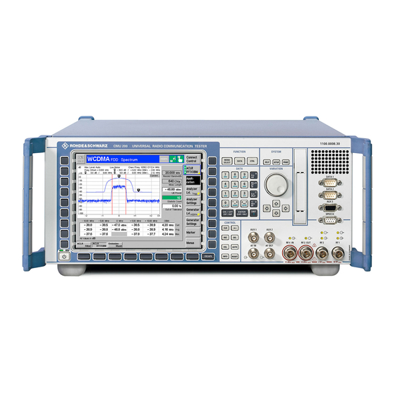
Universal Radio Communication Tester
Brand:
Rohde & Schwarz
| Category:
Test Equipment
| Size: 4 MB
Table of Contents
Figures
7
Table of Contents
7
Technical Information
11
R&S Technical Information R&S Cmu-B17
12
Block Diagram
12
Functionality
13
Applications
16
Ordering Information
18
Annex 1: Signal Paths R&S Cmu200 Incl. R&S Cmu-B17
19
Annex 2: Assignment of Iq / if Connectors on R&S Cmu Rear Panel
20
Annex 3: Location of R&S Cmu-B17 Connectors on Rear Panel
21
Annex 4: Specification
22
Chapter 1: Putting into Operation
39
Preparation for Use
45
Fig. 1-1 CMU Front View
47
Front and Rear View
47
Preparation for Use
47
Fig. 1-2 CMU Front View - Hardkeys
48
Fig. 1-3 CMU Front View - Hardkeys
49
Fig. 1-4 CMU Front View - Hardkeys
50
Fig. 1-5 CMU Front View Connectors
51
Fig. 1-6 CMU Front View- Connectors
52
Fig. 1-7 CMU Rear View
53
Rear View
53
Fig. 1-8 CMU Rear View – Signal Inputs and Outputs
54
Fig. 1-9 CMU Rear View - Abis and I/Q-IF Inputs and Outputs
55
Putting the Instrument into Operation
56
Unpacking the Instrument
56
Setting up the Instrument
56
Mounting in a Rack
57
Connecting the Instrument to the AC Supply
57
Switching on the Instrument / Startup Test
57
Switching off the Instrument
59
How to Ensure EMC
59
Input Level
59
Connecting the CMU to the Test Setup
60
Connecting a Controller
60
Connecting an External Keyboard
62
Connecting a Monitor
62
Connecting a Printer
63
Synchronization with External Devices; Connection of Further Components
63
Fig. 1-9 Versionmanager Main Screen (Example)
64
Software Update and Version Management
64
CMU Versionmanager
64
Table 1-1 Software Installation with the Versionmanager
66
RF User Correction
73
Compiling and Loading User Correction Tables
74
File Format for User Correction Tables
76
Ranges of Values and Limitations
76
Interpolation Rules
77
: Getting Started
79
Chapter 2: Getting Started
79
Getting Started
81
A Short Tutorial on CMU Operation
81
Condensed Operating Instructions
81
Startup of the CMU
84
RF Non Signalling Measurements
88
Chapter 3: Operation
81
How to Access and Close Menus
82
How to Use Dialog Elements in the Menus
83
Table of Contents
95
Controls
97
Fig. 3-1 Keys, Softkeys and Hotkeys
97
Front Panel Keys
98
Rotary Knob
98
Softkeys
98
Hotkeys
99
Fig. 3-2 Example of a Measurement Menu
100
Manual Operation
97
Operating Menus
100
Measurement Menus
100
Fig. 3-3 Example of Graphical Measurement Menu
103
Graphical Measurement Menus
103
Fig. 3-4 Example of a Popup Menu
104
Popup Menus
104
Operation of Popup Menus
105
Table 3-1 Operation of Popup Menus
105
Dialog Elements in the Menu
106
Input Fields
106
Input of Numbers
106
Input of Alphanumerical Characters
108
Table 3-2 Assignment of Numerical Keys and Alphanumeric Characters
108
Select Fields in Popup Menus
110
Table 3-3 Operation of Select Fields
110
Chapter 5: Remote Control – Basics
112
Measurement Control
112
Configurations
112
Measurement Groups
113
Table 3-4 Measurements in Function Group RF (Non Signalling)
113
General Settings
114
Table 3-5 Measurements in Function Group Audio (with Option CMU-B41)
114
Functions and Their Application
117
Chapter 6: Remote Control – Commands
119
Fig. 4-1 Startup Menu
119
Functions and Their Application
119
Startup Menu
119
Fig. 4-2 Popup Window Help
120
On-Screen Help (HELP Key)
120
Fig. 4-3 Popup Window Reset
121
Reset of Instrument Settings (RESET Key)
121
Fig. 4-4 Popup Window Print
122
Print Menu (PRINT Menu)
122
Fig. 4-5 Menu Select
124
Menu Select
124
Fig. 4-6 Printer Configuration Menu (Setup - Print)
127
Popup Menu Setup
127
Printer Settings (Setup - Print)
127
Fig. 4-7 IEC-Bus Menu
128
Remote-Control Settings (Setup - Remote)
128
Fig. 4-8 Interface Menu
130
Serial Interfaces (Setup - Comm.)
130
Enabling Options (Setup - Options)
131
Fig. 4-9 Options Menu
131
Fig. 4-10 Time Menu
134
Time Settings (Setup - Time)
134
Fig. 4-11 Setup - Misc. Menu
135
Acoustic Signal and Keyboard (Setup - Misc.)
135
Fig. 4-12 Info - Hardware Equipment
136
System Information (Info)
136
Hardware Equipment
136
Fig. 4-13 Info - Maintenance Menu
137
Selftest (Info - Maintenance)
137
Fig. 4-14 Selftest - Maintenance Menu
138
Selftest (Maintenance)
138
Data Handling (Data)
140
Saving Configurations (Data - Save)
140
Fig. 4-15 Data - Save Menu
140
Fig. 4-16 Data - Recall Menu
142
Loading Saved Configurations (Data - Recall)
142
Layer 3 Message Log (Data - Logging)
143
Chapter 9: Error Messages
143
Fig. 4-17 Data - Logging Menu
144
Transfer and Evaluation of Log Files
145
Fig. 4-18 Evaluation of Log Files
146
Fig. 4-19 Data - Arrange Menu
147
File Manager (Data - Arrange)
147
RF Measurements (RF)
151
Analyzer/Generator Menu
151
Fig. 4-19 Measurement Menu Analyzer / Generator
153
Test Settings
153
Measurement Results
155
Fig. 4-20 Analyzer/Generator Configuration - Control
156
Analyzer/Generator Configuration
156
Fig. 4-21 Measurement Menu Power
158
Measurement Menu (Power)
158
Power Vs. Time Measurement
158
Test Settings
158
Fig. 4-22 Display of Measurement Results (Power Menu)
162
Measurement Results
162
Fig. 4-23 Power Configuration - Control
163
Measurement Configurations (Power Configuration)
163
Fig. 4-24 Measurement Menu Spectrum
166
Measurement Menu (Spectrum)
166
Spectrum Measurement
166
Test Settings
167
Fig. 4-25 Display of Measurement Results (Spectrum Menu)
171
Measurement Results
171
Measurement Configurations (Spectrum Configuration)
172
Fig. 4-26 Spectrum Configuration - Control
173
Fig. 4-27 Connection Control - RF Analyzer Settings (Softkey)
176
Analyzer Settings (Connection Control - Analyzer)
176
Connection Control
176
Softkey-Oriented Version
176
Fig. 4-28 Connection Control - RF Analyzer Settings (Table)
177
Fig. 4-29 Connection Control - RF Generator Settings (Softkey)
179
Generator Settings (Connection Control - Generator)
179
Softkey-Oriented Version
179
Chapter 4 : Functional Description
179
Chapter 7 : Remote Control - Program Examples
179
Chapter 8 : Maintenance and Hardware Interfaces
179
Index
179
Fig. 4-30 Connection Control - RF Generator Settings (Table)
180
Re E-3
181
RF Connectors (Connection Control - RF)
183
Fig. 4-31 Connection Control - RF Connectors
184
Reference Frequency (Connection Control - Synch.)
186
Fig. 4-32 Connection Control - Synchronization
187
Trigger (Connection Control - Trigger)
190
I/Q-IF Interface (Connection Control - I/Q-IF)
192
Options and Extensions
194
Analyzer/Generator Menu
194
Audio Generator and Analyzer (Option CMU-B41)
194
Fig. 4-33 Measurement Menu Analyzer/Generator (Audio)
195
Test Settings
195
Fig. 4-34 Display of Test Settings and Measurement Results (Audio)
197
Measurement Results
197
Fig. 4-35 Analyzer Configuration - Control
199
Measurement Configurations (Analyzer Configuration)
199
Measurement Control (Analyzer Configuration - Control)
199
Fig. 4-36 Analyzer Configuration - Generator
200
Generator Settings (Analyzer Configuration - Generator)
200
Fig. 4-37 AF Analyzer Input Path Configuration
201
Fig. 4-38 Analyzer Configuration - Filter
201
Input Path Configuration (Analyzer Configuration - Filter)
201
Fig. 4-39 Measurement Menu Multitone
203
Multitone Measurement
203
Test Settings
203
Fig. 4-40 Display of Measurement Results (Multitone)
206
Measurement Results
206
Measurement Configurations (Multitone Configuration)
207
Measurement Control (Multitone Configuration - Control)
207
Fig. 4-41 Multitone Configuration - Control
208
Fig. 4-42 Multitone Configuration - Limit Lines
210
Limit Lines (Multitone Configuration - Limit Lines)
210
Fig. 4-43 Multitone Configuration - Tone Def
211
Test Tones (Multitone Configuration - Tone Def.)
211
Fig. 4-44 Signal Path for Multitone Measurements
212
Input Path Configuration (Multitone Configuration - Filter)
212
Fig. 4-45 Multitone Configuration - Filter
213
I/Q and if Interface (Option CMU-B17)
215
I/Q-IF Test Scenarios
215
Application Examples
218
Bit Error Rate Measurements on Digital Receivers under Fading Conditions4.98
218
Additional Information for GSM
219
CMU200 as I/Q Generator and RF Analyzer
219
CMU200 as RF Generator and I/Q Analyzer
220
Table of Contents
221
Introduction
223
Remote Control - Basics
223
Operation Via Remote Control
224
Switchover to Remote Control
224
Setting the Device Address
224
Fig. 5-1 Remote Screen
225
Indications During Remote Control
225
Return to Manual Operation
226
Setting the Transmission Parameters (RS-232 Interface)
227
GPIB Bus Messages
227
Interface Message
228
Device Messages (Commands and Device Responses)
228
Structure and Syntax of Device Messages
229
SCPI Introduction
229
Command Structure
229
Fig. 5-2 Example for the Tree Structure of the SCPI Command Systems; the Source System
230
Structure of a Command Line
231
Responses to Queries
232
Parameters
232
Overview of Syntax Elements
234
Instrument Model and Command Processing
235
Input Unit
235
Fig. 5-3 Instrument Model in the Case of Remote Control Via GPIB Bus
235
Command Recognition
236
Data Set and Instrument Hardware
236
Status Reporting System
236
Output Unit
236
Table 5-1 Synchronization with *OPC, *OPC? and *WAI
237
Command Sequence and Command Synchronization
237
Fig. 5-4 the Status Register Model
238
Status Reporting System
238
Structure of an SCPI Status Register
238
Overview of the Status Registers
240
Fig. 5-5 the Status Registers
241
Table 5-2 Meaning of the Bits Used in the Status Byte
242
Status Byte (STB) and Service Request Enable Register (SRE)
242
Table 5-3 Meaning of the Bits Used in the Event Status Register
243
Event Status Register (ESR) and Event Status Enable Register (ESE)
243
IST Flag and Parallel Poll Enable Register (PPE)
243
Status:operation Register
244
Table 5-4 Meaning of the Bits Used in the Status:operation:cmu:sum1:Cmu1 Sub-Register Assigned to the CMU Base System
244
Table 5-5 Meaning of the Bits Used in the Status:operation:cmu:sum1|2:Cmu<Nr> Sub-Register Assigned to RF Non Signalling
244
Status:questionable-Register
245
Application of the Status Reporting Systems
246
Service Request
246
Parallel Poll
247
Serial Poll
247
Symbolic Status Event Register Evaluation
247
Error Queue Query
248
Query by Means of Commands
248
Reset Values of the Status Reporting Systems
249
Table 5-6 Resetting Instrument Functions
249
Measurement Control
250
Applications
250
Measurement Control Commands and States
250
Fig. 5-7 Measurement States and Control Commands
251
Event Reporting
253
Measurement Status
254
Fig. 5-8 Generator States and Control Commands
255
Generator Control
255
Table 5-7 Repetition Mode in Remote Control
256
Generator Status
256
Measurement Statistics
256
Retrieving Measurement Results
257
Diagrammatic Overview of Measurement Control
260
Single Shot Measurements
260
Counting Measurements
261
Continuous Measurements
262
Special Terms and Notation
263
Remote Control - Commands/Subsystem Input, Output, Correction:loss ( /Ext. Att.)
265
Common Commands
267
Remote Control - Commands
267
Table 6-1 Common Commands
267
CMU Base System
271
System Commands
271
Status Commands
272
Symbolic Status Event Register Evaluation
275
Setup - Basic Device Settings
276
Subsystem Remote
276
Subsystem Communicate
277
Subsystem Options
278
Subsystem Time
279
Subsystem MISC
280
Subsystem Gtrmode (Local to Remote Switchover)
281
Subsystem Mqueue
281
Reset of Function Groups
282
Remote Report - Subsystem Trace
283
File Manager - System Mmemory
284
Synchronization
289
RF Measurements
291
Subsystem Options
291
Configuration File Management - System Mmemory
291
Partial Reset
292
Connection Control
292
Subsystem Trigger (Trigger Mode)
294
Measurement Control - Subsystem Rfanalyzer
296
Subsystem Rfanalyzer
296
Results - Subsystem Rfanalyzer:power
298
Subsystem Rfanalyzer:control
298
Subsystem Rfgenerator
299
Subsystem Rfgenerator (Generator Control)
299
Subsystem Rfgenerator
300
Subsystem Rfgenerator:modulation (Frequency Modulation)
301
Subsystem Rfgenerator:fhopping (Frequency Hopping)
302
Subsystem Rfgenerator:auxtx
303
Subsystem Rfgenerator:bandwidth (Bandwidth)
303
Subsystem Rfgenerator:pulse (Ramping)
303
Subsystem Input, Output, Correction:loss ( /Ext. Att.)
305
Subsystem DM:clock (Synchronization)
306
I/Q-IF Interface
307
Power Measurements (Power)
310
Measurement Control - Subsystem Power
310
Subsystem Power:control (Control)
311
Test Configuration
311
Subsystem Power:frequency (Frequency/Rbw)
312
Subsystem Power:level (Level)
312
Subsystem Power:time
313
Subsystem Subarrays:power
314
Results - Subsystem Power
315
Spectrum Measurements (Spectrum)
317
Subsystem Spectrum:control
318
Test Configuration
318
Subsystem Spectrum:frequency (Frequency/Rbw)
319
Subsystem Spectrum:level (Level)
320
Subsystem Subarrays:spectrum
320
Results - Subsystem Spectrum
321
Wpower
323
Measured Values - Subsystem Wpower
324
Npower (Function Group RF)
325
Subsystem Npower:control
326
Subsystem Npower:frequency (RBW)
327
Measured Values - Subsystem Npower
328
Symbolic Status Event Register Evaluation
329
Audio Generator and Analyzer (with Option CMU-B41)
330
Subsystem Options
331
Configuration File Management - System Mmemory
331
Partial Reset
332
Subsystem Aflevel (AF Input Level)
332
Audio Analyzer (Afanalyzer)
334
Subsystem Afanalyzer (Measurement Control)
334
Subsystem Afanalyzer
335
Subsystem Afanalyzer
336
AF Generator (Afgenerator)
339
Multitone Measurements (Multitone)
341
Measurement Control - Subsystem Multitone
341
Subsystem Multitone
343
Test Configuration
343
Subsystem Subarrays:multitone
344
Tolerance Values - Subsystem Multitone
345
Test Tones - Subsystem Multitone
347
Path Configuration - Subsystem Multitone:af1Channel:filter
349
Results - Subsystem Multitone
352
Table 6-1 List of Remote-Control Commands: CMU Base System
355
List of Commands
355
Table 6-2 List of Remote-Control Commands: RF Measurements
357
Table 6-3 List of Remote-Control Commands: Audio Measurements
362
Table 6-4 Alphabetical List of Remote-Control Commands: Base System
367
Alphabetical Command Lists
367
Table 6-5 Alphabetical List of Remote-Control Commands: RF
368
Table 6-6 Alphabetical List of Remote-Control Commands: Audio
371
Remote Control - Program Examples
375
Remote Control - Program Examples
377
Secondary Address Handling
377
Simple Measurements
378
Measuring the I/Q Spectrum of a Mobile
379
Tips and Tricks for CMU Programming
383
Table of Contents
385
Maintenance
387
Cleaning the Outside
387
Maintenance and Interfaces
387
Storing and Packing
387
Fig. 8-1 Pin Assigment of the GPIB Bus Interface
388
Hardware Interfaces
388
Bus Lines
388
Characteristics of the Interface
388
GPIB Bus Interface
388
Interface Messages
390
Table 8-1 Universal Commands
390
Table 8-2 Addressed Commands
390
Fig. 8-2 Pin Assignment of the RS-232-C Interface
391
Interface Characteristics
391
Serial Interfaces (COM 1, COM 2)
391
Signal Lines
392
Transmission Parameters
392
Interface Functions
393
Table 8-3 Transmission Parameters of the RS-232 Interface
393
Table 8-4 Control Strings or Control Characters of the RS-232-C Interface
393
Fig. 8-3 Wiring of the Data Lines for Software Handshake
394
Handshake
394
Fig. 8-4 Wiring of the Data, Control and Message Lines for Hardware Handshake
395
Connectors for Peripherals
396
Fig. 8-5 Pin Assignment of the LPT Connector
396
Printer Connector (LPT)
396
Fig. 8-6 Pin Assignment of the MONITOR Connector
397
Fig. 8-7 Pin Assignment of the KEYBOARD Socket
397
Keyboard Connector (KEYBOARD)
397
Monitor Connector (MONITOR)
397
Fig. 8-8 RF Connectors
398
Fig. 8-9 Inputs and Outputs for Reference Frequency
398
Inputs and Outputs for the Reference Frequency (REF
398
RF Connectors
398
Signal Inputs and Outputs
398
Fig. 8-10 AF Connector SPEECH
399
Fig. 8-11 if Signal Output
399
Fig. 8-12 SERVICE Connector
399
AF Connector SPEECH (Optional)
399
IF Signal
399
Service and Auxiliary Connectors
399
Fig. 8-13 aux Connector
400
Fig. 8-14 aux 3 Connector
400
Abis Connector (CMU300 with Option CMU-B71 Only)
401
Fig. 8-15 aux 4 Connector
401
Fig. 8-17 I/Q CH1 Connector
402
I/Q CH1 Connector (CMU200 with Option CMU-B17 Only)
402
Fig. 8-18 IF3 Connectors
403
IF3 Connectors (CMU200 with Option CMU-B17 Only)
403
Error Messages
407
Command Error
407
No Error
407
SCPI Error Messages
407
Execution Error
409
Device-Specific Error
411
Query Error - Error Upon Data Request
412
Advertisement
Rohde & Schwarz CMU 200 Service Manual (216 pages)
Universal Radio Communication Tester
Brand:
Rohde & Schwarz
| Category:
Test Equipment
| Size: 4 MB
Table of Contents
Table of Contents
7
Performance Test
15
A) Calibration by an R&S Representative with an ACS Calibration System
15
B) Sending the Instrument to the Factory (Memmingen, Germany)
15
General
15
Necessary Documents
15
Measuring Instruments and Auxiliary Equipment
16
Reference Frequencies
17
Test Setups
17
TX Level Measurements
17
General TX Measurements
18
RX Level Measurements
18
General RX Measurements
19
RX Demodulation Measurements
19
Tolerance Analysis
20
Manual Test Procedure
21
Selftest
21
IEC-Bus Interface
22
Interface
22
Interface Test
22
Ref in
22
Reference Frequencies
22
Ref out 1
23
TX Frequency Accuracy
24
TX Frequency Settling Time
24
TX Level Error
24
Vswr
24
TX Harmonics
25
TX In-Band Spurious Signals
25
TX Level Settling Time
25
TX Non Harmonics
25
TX Fixed Spurious Signals
26
TX Residual am
26
TX Residual FM
26
TX SSB Phase Noise
26
RX Harmonics
27
RX Power Meter (Frequency-Selective)
27
RX Power Meter (Wideband)
27
TX Carrier/Sideband Suppression, Max. Distortion
27
RX Spurious Response / Image Rejection
28
RX SSB Phase Noise
28
RX Dynamic/ Average Noise Level
29
RX Residual FM/AM
29
Options for CMU200
30
RX GSM Demodulation
30
TX GSM Modulation
30
AMPS-Mobile Test
31
CDMA Mobile Test
31
Function Test with Mobile Stations (CMU200)
31
GSM Mobile Test
31
IS136-Mobile Test
31
Test Report
32
Chapter 1 : Performance Test
53
Chapter 2 Adjustment
53
Preparing the Instrument
54
Adjusting the 10 Mhz Reference Frequency
55
Automatic Adjustment of Module Data
56
Chapter 3 Repair
57
Block Diagram
58
Instrument Frame
59
Cooling the Instrument
60
Front Module
61
Power Supply
62
Motherboard
63
Reference Board
64
Option OCXO REFERENCE OSC. CMU-B11 or B12
65
Rf Frontend
65
Rxtx Board1
66
Digital Board
68
Option UNIVERSAL SIGNALLING UNIT CMU-B21
69
Option AUDIO-GEN. + ANA. CMU-B41
71
Option CDMA (IS95) Signalling Unit CMU-B81
72
MODULE Replacement
73
Opening the Instrument and Removing the FRONT MODULE
73
Replacing the FRONT MODULE
73
Installing the New FRONT MODULE and Completing the Instrument
74
Putting into Operation
74
Opening the Instrument and Removing the FRONT MODULE
75
Replacing the FRONT MODULE CONTROLLER in the FRONT MODULE
75
Installing the New FRONT MODULE CONTROLLER
76
Installing the Option Again and Completing the Instruments
76
Removing the FRONT MODULE CONTROLLER from the FRONT MODULE3.20
76
Putting into Operation
77
Opening the Instrument and Removing the FRONT MODULE
78
Replacing the Lithium Battery in the FRONT MODULE
78
Removing the Lithium Battery
79
Installing the New Battery and Completing the Instrument
80
Putting into Operation
80
Opening the Instrument and Removing the FRONT MODULE
81
Replacing the Hard Disk in the FRONT MODULE
81
Installing the New Hard Disk
82
Removing the Hard Disk from the FRONT MODULE
82
Putting into Operation
83
Opening the Instrument and Removing the FRONT MODULE
84
Replacing the Memory Modules in the FRONT MODULE
84
Installing the New Memory Module and Completing the Instrument
85
Making the Memory Modules Accessible
85
Putting into Operation
85
Removing the Memory Module
85
Opening the Instrument and Removing the FRONT MODULE
86
Replacing the LCD And/Or DC/AC Converter in the FRONT MODULE
86
Installing the New LCD And/Or DC/AC Converter and Completing the Instrument3.31
87
Making the LCD Accessible
87
Putting into Operation
87
Removing the LCD And/Or DC/AC Converter
87
Opening the Instrument and Removing the FRONT MODULE
88
Replacing the Keyboard Membrane And/Or Mat on the FRONT MODULE
88
Installing the New Membrane and Completing the Instrument
89
Putting into Operation
89
Removing the Membrane
89
Installing the New Labeling Panel and Completing the Instrument
90
Putting into Operation
90
Removing the Old Labeling Panel
90
Replacing the Labeling Panel on the FRONT MODULE
90
Opening the Instrument and Removing the FRONT MODULE
91
Replacing the Options FLOPPY DISK DRIVE CMU-B61 or PCMCIA INTERFACE
91
Completing the Instrument and Putting into Operation
92
Replacing the Option
92
Replacing the RF FRONTEND
93
Automatic Module Data Adjustment
93
Installing the New RF FRONTEND MODULE and Completing the Instrument3.37
93
Opening the Instrument and Removing the RF FRONTEND
93
Replacing the REFERENCE BOARD
94
Automatic Module Data Adjustment
94
Installing the New REFERENCE BOARD and Completing the Instrument
94
Opening the Instrument and Removing the REFERENCE BOARD
94
Replacing the RXTX BOARD1
95
Automatic Module Data Adjustment
95
Installing the New RXTX BOARD1 and Completing the Instrument
95
Opening the Instrument and Removing the RXTX BOARD1
95
Replacing the TR-CORRECTION MODULE in the RXTX BOARD1
96
Automatic Module Data Adjustment
96
Installing the New TR-CORRECTION BOARD and Completing the Instr
96
Opening the Instrument and Removing the TR-CORRECTION MODULE
96
Replacing the DIGITAL BOARD
97
Automatic Module Data Adjustment
97
Installing the New DIGITAL BOARD and Completing the Instrument
97
Opening the Instrument and Removing the DIGITAL BOARD
97
Replacing the MODULES: ADC MODULE1, DDC MODULE1, TXDSP MODULE1, AUC MODULE1 in the DIGITAL BOARD
98
Installing the New Sandwich Module and Completing the Instrument
98
Opening the Instrument and Removing the Modules
98
Automatic Module Data Adjustment
99
Replacing the Option OCXO REFERENCE OSC. CMU-B11 or CMU-B12
100
Installing the New OPTION OCXO REFERENCE OSC. and Completing the
100
Manual OCXO Adjustment
100
Replacing the Option UNIVERSAL SIGNALLING UNIT CMU-B21
101
Automatic Module Data Adjustment
101
Installing the New OPTION UNIV. SIGN. UNIT and Completing the Instr
101
Opening the Instrument and Removing the OPTION UNIV. SIGN. UNIT
101
Replacing the MODULES: DSP MODULE0/1, IQOUT MODULE, OPTION SPEECH CODEC CMU-B52 (INCLUDES DSP MODULE3) in the UNIV. SIGN. UNIT
102
Installing the New Sandwich Module and Completing the Instrument
102
Opening the Instrument and Removing the Modules
102
Automatic Module Data Adjustment
103
Replacing the Option AUDIO-GEN. + ANA. CMU-B41
104
Automatic Module Data Adjustment
104
Installing the New Option AUDIO-GEN. + ANA. and Completing the Instr
104
Opening the Instrument and Removing the Option AUDIO-GEN. + ANA
104
Replacing the POWER SUPPLY
105
Installing the New POWER SUPPLY
105
Removing the POWER SUPPLY
105
Replacing the Instrument Fan
106
Installing the New Fan and Completing the Instrument
106
Opening the Instrument and Removing the Fan
106
Installing the New MOTHERBOARD1 and Completing the Instrument
107
MOTHERBOARD1 (Big MOTHERBOARD)
107
Opening the Instrument and Removing MOTHERBOARD1
107
Replacing the MOTHERBOARD
107
FRONTPANEL BOARD (at the Front of the Instrument Frame)
108
Installing the New FRONTPANEL BOARD and Completing the Instrument
108
Installing the New MOTHERBOARD2 and Completing the Instrument
108
MOTHERBOARD2 (Small MOTHERBOARD)
108
Opening the Instrument and Removing MOTHERBOARD2
108
Opening the Instrument and Removing the FRONTPANEL BOARD
108
Installing the New REARPANEL BOARD1 and Completing the Instrument
109
Installing the New REARPANEL BOARD2 and Completing the Instrument
109
Opening the Instrument and Removing the REARPANEL BOARD1
109
Opening the Instrument and Removing the REARPANEL BOARD2
109
REARPANEL BOARD1 (Interface Board for Standard Connectors at the Rear of the Instrument Frame)
109
REARPANEL BOARD2 (Interface Board for Further Connectors at the Rear of the Instrument Frame)
109
Troubleshooting
110
Troubleshooting Using the Leds (H1 to H8) on the MOTHERBOARD
111
Troubleshooting Using the SELFTEST Menu for Modules
113
Troubleshooting Using the INFO Menu for Modules
114
Troubleshooting Using the ERROR Messages on the LC Display
116
General Errors on the Transmitter Side of the CMU
117
More Troubleshooting
117
General Errors on the Receiver Side of the CMU
118
Software Update/Installing Options
119
New Installation of the CMU Software
119
Software Update Via FLOPPY DISK DRIVE
119
Software Update Via PCMCIA INTERFACE
119
Performing a Software Update
120
Loading Software as Long as There Is no Versionmanager in the CMU
121
Reinstalling the Old Software
121
Installing the Options
122
Installation of Option Cmu-B11 Ocxo Ref.osc. (1100.5000.02)
125
Preparation
126
Installation of Option
127
Assembling Unit
128
Functional Test of Option CMU-B11
129
Installation of Option Cmu-B12 Ocxo Ref.osc. (1100.5100.02)
131
Preparation
132
Installation of Option
133
Assembling Unit
134
Functional Test of Option CMU-B11
135
Installation of Option Cmu-B21 Univ. Sign. Unit (1100.5200.02)
137
Preparation
138
Installation of Option
140
Assembling Unit
141
Functional Test of Option CMU-B21
142
Installation of Option Cmu-B41 Audio-Gen.+Ana. (1100.5300.02)
143
Preparation
144
Installation of the Option
146
Fitting
146
Cabling
147
Assembly of Unit
148
Affixing Option Label
148
Fitting Enclosure
148
Functional Test of Option CMU-B41
149
Automatic Module Data Adjustment
149
Checking Option Detection
149
Checking the Function
149
Installation of Option Cmu-B52 Speech Codec (1100.5400.02)
151
Preparation
152
Installation of Option
154
Assembling Unit
156
Affixing Option Label
156
Putting Cover Back
156
Functional Test of Option CMU-B52
157
Automatic Module Data Adjustment
157
Test of Option Detect
157
Installation of Option Cmu-B53 Bluetooth F.cmu (1100.5700.02)
159
Preparation
160
Installation of Option
162
Modification of Universal Link Handler (Fig. 4)
163
Assembling the Unit
164
Functional Test of Option CMU-B53
164
Modification Kit Cmu-U53 Bluetooth F.cmu (1100.7302.02)
165
Preparation
166
Board Exchange
168
Modification of Universal Link Handler
169
Assembling the Unit
174
Functional Test of Modification Kit CMU-U53
174
Installation of Option Cmu-U61 Floppy Diskdrive (1100.5500.02)
177
Preparation
178
Installation of Option
181
Assembling Unit
184
Functional Test of Option CMU-U61
185
Installation of Option Cmu-B71 Abis Interface Unit (1100.6406.02)
187
Preparation
188
Installation of Option
190
Assembling Unit
191
Functional Test of Option CMU-B71
191
Installation of Option Cmu-B81 Cdma Sign. Unit (1100.6506.02)
193
Preparation
194
Installation of Option
196
Assembling Unit
197
Functional Test of Option CMU-B81
198
Chapter 4 : Software Update /Installation of Options
199
Chapter 5 Documents
199
Table 5-1 List of Power Cables Available
200
Rohde & Schwarz CMU 200 Service Manual (199 pages)
Universal Radio Communication Tester
Brand:
Rohde & Schwarz
| Category:
Test Equipment
| Size: 5 MB
Table of Contents
Safety Instructions
5
Table of Contents
7
1 Performance Test
19
General
19
A) Calibration by an R&S Representative with an ACS Calibration System
19
B) Sending the Instrument to the Factory (Memmingen, Germany)
19
Necessary Documents
19
Measuring Instruments and Auxiliary Equipment
20
Table 1-1 Measuring Instruments and Auxiliary Equipment for Manual Performance Test
20
Reference Frequencies
21
Test Setups
21
TX Level Measurements
21
General TX Measurements
22
General RX Measurements
23
RX Demodulation Measurements
23
RX Level Measurements
23
Tolerance Analysis
24
Manual Test Procedure
25
Selftest
25
Interface Test
26
IEC-Bus Interface
26
RS-232 Interface
26
Reference Frequencies
27
Ref
27
Ref out 1
28
TX Frequency Accuracy
29
TX Frequency Settling Time
29
TX Level Error
29
Vswr
29
TX Level Settling Time
30
TX Harmonics
30
TX Non Harmonics
30
TX In-Band Spurious Signals
30
TX Fixed Spurious Signals
31
TX SSB Phase Noise
31
TX Residual
31
TX Carrier/Sideband Suppression, Max. Distortion
32
RX Power Meter (Frequency-Selective)
32
RX Power Meter (Wideband)
32
RX Harmonics
33
RX Spurious Response / Image Rejection
33
RX SSB Phase Noise
33
RX Residual FM/AM
34
RX Dynamic/ Average Noise Level
34
Options for R&S CMU200
35
Gsm
35
RX GSM dem Odulation
35
TX GSM Modulation
35
Cdma2000
36
TX CDMA2000 Modulation
36
RX CDMA2000 dem Odulation
37
RX WCDMA dem Odulation
38
TX WCDMA Modulation
38
Wcdma
38
Function Test with Mobile Stations (R&S CMU200)
39
CDMA Mobile Test
39
CDMA2000 Mobile Test
39
GSM Mobile Test
39
IS136-Mobile Test
39
AMPS-Mobile Test
40
Test Report
41
Table 1-2 Test Report
41
2 Adjustment
71
Manual Adjustment
71
Measuring Instruments and Auxiliary Equipment
71
Table 2-1 Measuring Instruments and Auxiliary Equipment for Manual Adjustment of the R&S CMU
71
Preparing the Instrument
72
Adjusting the + 5 VDC Reference Voltage
72
Adjusting the 10 Mhz Reference Frequency
73
Ocxo Reference Osc. R&S Cmu -B11
73
Ocxo Reference Osc. R&S Cmu -B12
73
Tcxo
73
Automatic Adjustment of Module Data
74
Preparing the Adjustment
74
Performing the Adjustment
74
Block Diagram
76
Instrument Frame
77
Cooling the Instrument
78
Front Module
79
Power Supply
80
Motherboard
81
REARPANEL Board2
82
Reference Board
83
Option OCXO REFERENCE OSC. R&S CMU-B11 or B12
84
Rxtx Board1
85
Digital Board
87
Option UNIVERSAL SIGNALLING UNIT R&S CMU-B21 Var02
88
Option UNIVERSAL SIGNALING UNIT R&S CMU-B21 Var 14/54
90
Option AUDIO-GEN. + ANA. R&S CMU-B41
92
Option WCDMA L1COPRO R&S CMU-B66/68/76/78
93
Option CDMA (IS95) Signaling Unit R&S CMU-B81
95
Option CDMA2000 Signaling Unit R&S-B83 Var12
96
Option CDMA2000 Signaling Unit R&S CMU-B83 Var22
97
MODULE Replacement
99
Installing the New FRONT MODULE and Completing the Instrument
100
Replacing the FRONT MODULE CONTROLLER in the FRONT MODULE
101
Removing the FRONT MODULE CONTROLLER
102
Putting into Operation
103
Replacing the Lithium Battery in the FRONT MODULE
104
Removing the Lithium Battery and Installing the New Battery
105
Completing the Instrument
106
Replacing the Hard Disk in the FRONT MODULE
107
Replacing the Memory Modules in the FRONT MODULE
108
Making the Memory Modules Accessible
109
Putting into Operation
110
Replacing the LCD And/Or DC/AC Converter in the FRONT MODULE
111
Making the LCD Accessible
112
Replacing the Keyboard Membrane And/Or Mat on the FRONT MODULE
113
Removing the Membrane
114
Replacing the Labeling Panel on the FRONT MODULE
115
Replacing the Options FLOPPY DISK DRIVE R&S CMU-B61 or PCMCIA INTERFACE
116
Replacing the Option
117
Replacing the RF FRONTEND
118
Replacing the REFERENCE BOARD
119
Replacing the RXTX BOARD1
120
Replacing the TR-CORRECTION MODULE in the RXTX BOARD1
121
Replacing the DIGITAL BOARD
122
Replacing the MODULES: ADC MODULE1, DDC MODULE1, TXDSP MODULE1, AUC MODULE1 in the DIGITAL BOARD
123
Automatic Module Data Adjustment
124
Replacing the Option OCXO REFERENCE OSC. R&S CMU-B11 or R&S CMU-B12
125
Replacing the Option UNIVERSAL SIGNALLING UNIT R&S CMU-B21 Var02
126
Var02
127
Replacing the Option UNIVERSAL SIGNALLING UNIT CMU-B21 Var14/54
129
Automatic Module Data Adjustment
131
Installing the New Sandwich Module and Completing the Instrument
133
Installing the New OPTION CDMA2000 SIGNALING UNIT and Completing the Instrument
134
Installing the New Sandwich Module and Completing the Instrument
137
Replacing the Option AUDIO-GEN. + ANA. CMU-B41
138
Replacing the POWER SUPPLY
139
Replacing the Instrument Fan
140
Replacing the MOTHERBOARD (1100.0908.02)
141
MOTHERBOARD2 (Small MOTHERBOARD)
142
REARPANEL BOARD1 (Interface Board for Standard Connectors at the Rear of the Instrument Frame)
143
Of the Instrument Frame) Opening the Instrument and Removing the REARPANEL BOARD2
146
Troubleshooting
147
Troubleshooting Using the Leds (H1 to H8) on the MOTHERBOARD
148
Troubleshooting Using the SELFTEST Menu for Modules
150
Using the Error Messages
152
More Troubleshooting
153
General Errors on the Receiver Side of the R&S CMU
154
4 Software Update/Installing Options
155
Performing a Software Update
156
Reinstalling the Old Software
157
Installing the Options
158
List
159
Table 5-1 List of Power Cables Available
160
Advertisement
Advertisement
Related Products
Rohde & Schwarz CMU 300
Rohde & Schwarz CMU 200A
Rohde & Schwarz R&S CMU-Z10
Rohde & Schwarz R&S CMU-Z11
Rohde & Schwarz R&S CMU-Z12
Rohde & Schwarz R&S CMU-Z13
Rohde & Schwarz CMU-Z14
Rohde & Schwarz R&S CMW-KG200
Rohde & Schwarz CMW-KS8 Series
Rohde & Schwarz CMW-KE800
Rohde & Schwarz Categories
Measuring Instruments
Test Equipment
Portable Generator
Power Supply
Accessories
More Rohde & Schwarz Manuals
Login
Sign In
OR
Sign in with Facebook
Sign in with Google
Upload manual
Upload from disk
Upload from URL