
Related Manuals for Rohde & Schwarz CMU 200


Summary of Contents for Rohde & Schwarz CMU 200
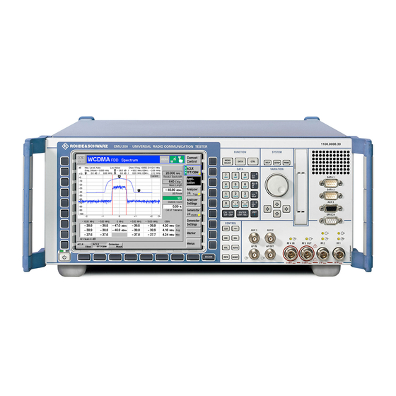
- Page 1 Service Manual Instrument Universal Radio Communication Tester R&S CMU 200 1100.0008.02/53 R&S CMU 300 1100.0008.03 Printed in Germany Test and Measurement Division 1100.4903.82-05...
- Page 2 ® R&S is a registered trademark of Rohde & Schwarz GmbH & Co. KG. Trade names are trademarks of the owners.
- Page 3 R&S CMU Tabbed Divider Overview Tabbed Divider Overview Spare Parts Express Service List of R&S Representatives Safety Instructions Contents Contents of Manuals for Universal Radio Communication Tester R&S CMU Tabbed Divider Chapter 1: Performance Test Chapter 2: Adjustment Chapter 3: Repair Chapter 4: Software Update / Installation of Options...
-
Page 5: Safety Instructions
Safety Instructions WARNING Danger of injuries When removing the rear feet, the unit can slip out of the cabinet. Put the unit onto the front handles, before removing the rear feet and taking off the cabinet. Thus the risk of personal injuries and damages to the unit is avoided. When mounting the cabinet take care not to pen in the fingers. -
Page 7: Table Of Contents
Contents Contents 1 Performance Test ........................1.1 General ..............................1.1 Calibration by an R&S Representative with an ACS Calibration System ..1.1 Sending the Instrument to the Factory (Memmingen, Germany) ......1.1 Necessary Documents ......................1.1 Measuring Instruments and Auxiliary Equipment.................1.2 Test Setups ..........................1.3 Reference Frequencies....................1.3 TX Level Measurements ....................1.3 General TX measurements....................1.4 RX Level measurements....................1.5... - Page 8 Contents TX Carrier/Sideband Suppression, Max. Distortion ...............1.14 RX Power Meter (Frequency-Selective).................1.14 RX Power Meter (Wideband) ....................1.14 RX Harmonics ........................1.15 RX Spurious Response / Image Rejection................1.15 RX SSB Phase Noise......................1.15 RX Residual FM/AM.......................1.16 RX Dynamic/ Average Noise Level ..................1.16 Options for R&S CMU200 ......................1.17 GSM-MS ........................1.17 TX GSM Modulation.....................1.17 RX GSM Dem...
- Page 9 Contents 3 Repair ..............................3.1 Instrument Design and Function Description ................3.1 Block diagram ..........................3.2 Instrument Frame........................3.3 Rear of Instrument Frame ......................3.3 Front of Instrument Frame .......................3.3 Cooling the Instrument ......................3.4 FRONT MODULE ........................3.5 POWER SUPPLY ........................3.6 MOTHERBOARD ........................3.7 REFERENCE BOARD ......................3.9 Option OCXO REFERENCE OSC.
- Page 10 Contents Replacing the Memory Modules in the FRONT MODULE .............3.34 Opening the instrument and removing the FRONT MODULE ......3.34 Making the memory modules accessible ............3.35 Removing the memory module ...............3.35 Installing the new memory module and completing the instrument ....3.35 Putting into operation ..................3.36 Replacing the LCD and/or DC/AC Converter in the FRONT MODULE .........3.37 Opening the instrument and removing the FRONT MODULE ......3.37...
- Page 11 Contents Replacing the Option OCXO REFERENCE OSC. R&S CMU-B11 or R&S CMU-B12 ..3.51 Opening the instrument and rem. the OPTION OCXO REFERENCE OSC...3.51 Installing the new OPTION OCXO REFERENCE OSC. and completing the instrument ................3.51 Manual OCXO adjustment ................3.51 Replacing the Option UNIVERSAL SIGNALLING UNIT R&S CMU-B21 Var02 ....3.52 Opening the instrument and removing the OPTION UNIV.
- Page 12 Contents Replacing the MODULES: 1xEV-DO MODULE CMU-B89, SPEECH CODEC MODULE CMU-B85 VAR22, POWER QUICC3 MODULE in the CDMA2000 Signaling Unit CMU-B83 Var22 ........................3.62 Opening the instrument and removing the modules ........3.62 Installing the new sandwich module and completing the instrument ....3.63 Automatic module data adjustment..............3.63 Replacing the Option AUDIO-GEN.
- Page 13 Tables Troubleshooting ..........................3.73 Troubleshooting using the LEDs (H1 to H8) on the MOTHERBOARD ........3.74 Troubleshooting using the SELFTEST Menu for Modules.............3.76 More troubleshooting......................3.79 General errors on the transmitter side of the R&S CMU............3.79 General errors on the receiver side of the R&S CMU ............3.80 4 Software Update/Installing Options ...................4.1 New Installation of the CMU Software....................4.1...
- Page 14 Tables Tables Table 1-1 Measuring instruments and auxiliary equipment for manual performance test......1.2 Table 1-2 Test report ..........................1.18 Table 2-1 Measuring instruments and auxiliary equipment for manual adjustment of the R&S CMU ...2.1 Table 5-1 List of power cables available ....................5.2 1100.4903.82...
- Page 15 R&S CMU Index Index DSP Module0/1 ....3.53, 3.55, 3.58, 3.60, 3.62 FLOPPY Disk Drive R&S CMU-B61 .......3.42 Front Module ............3.25 FRONT Module Controller ........3.27 ADC Module1 (DIGITAL Board) ........3.13 FRONTPANEL Board........3.68, 3.71 Adjustment Hard Disk ...............3.33 + 5 VDC Reference Voltage ........2.2 Instrument fan ............3.66 10 MHz Reference-Frequency .........
- Page 16 R&S CMU Index REARPANEL Board2 ............. 3.8 Adjustment ...............2.3 REFERENCE Board............3.9 Function ..............3.9 Reference frequencies ........... 1.9 Test report ..............1.23 Repair ................3.1 Tolerance analysis............1.6 RF Frontend ..............3.10 Troubleshooting RX Dynamic / average noise level........ 1.16 General errors ............3.79 RX GSM Demodulation ......
- Page 17 R&S CMU Documentation Contents of Manuals for Universal Radio Communi- cation Tester R&S CMU200/ R&S CMU300 Service Manual Instrument This service manual for Universal Radio Communication Tester R&S CMU provides information on checking the instrument for compliance with rated specifications, as well as on adjustment, repair and troubleshooting.
-
Page 19: Performance Test
R&S CMU General Performance Test This chapter provides the necessary information for checking the technical data of the R&S CMU. Please read the general notes on the test procedure on page 1.7 first. Then follows a list of the measuring equipment required for the performance test; a form for the test report is to be found at the end of this chapter. -
Page 20: Measuring Instruments And Auxiliary Equipment
Measuring Instruments and Auxiliary Equipment R&S CMU Measuring Instruments and Auxiliary Equipment Table 1-1 Measuring instruments and auxiliary equipment for manual performance test Item Type of instrument Required characteristics Appropriate device R & S order number Signal generator 100 kHz to 2.7 GHz, R&S SME03 1038.6002.03 RX measurements... -
Page 21: Test Setups
R&S CMU Measuring Instruments and Auxiliary Equipment Test Setups The quality of the test setup has an effect on the measurement procedures. Note: Make sure to use only high-quality coax cables and coax connectors as well as calibrated measuring equipment. Reference Frequencies Test setup REF1: REF1... -
Page 22: General Tx Measurements
Measuring Instruments and Auxiliary Equipment R&S CMU -33 dBm/ -16 dBm NRVD NRV-Z4 (CMU) RF1 / -93 dBm to -33 dBm/ -76 dBm to -16 dBm/ -55 dBm to +5 dBm FSIQ or FSE (CMU) RF1 / RF2 / RF3 OUT 10 MHz Reference Freq. -
Page 23: Rx Level Measurements
R&S CMU Measuring Instruments and Auxiliary Equipment RX Level measurements Test setup RX1, RX2 (depending on level range): NRV- NRVD Power Power Splitter Ampl. depending on max. level of power splitter (CMU) NRV- NRVD -30 dB Power direct. coupl Ampl. (CMU) General RX Measurements Test setup RX3:... -
Page 24: Tolerance Analysis
Tolerance Analysis R&S CMU Tolerance Analysis Due to the small measurement uncertainty of the R&S CMU, the measuring equipment must meet stringent requirements. Since the measurement uncertainty of the measuring equipment to be achieved depends on the test setup used, it is recommended to perform a tolerance analysis. To be able to trace back errors in the measurement, the measurement uncertainty should also be indicated in the test report. -
Page 25: Manual Test Procedure
R&S CMU Manual Test Procedure Manual Test Procedure Some additional measurements can only be performed using a mobile phone via the normal operating menus of the R&S CMU. These measurements are described in the section 'Function Test with Mobile Stations'. The suggested frequencies and levels at which the measurements should be performed have been selected according to the instrument concept. -
Page 26: Interface Test
Manual Test Procedure R&S CMU Selftest of the R&S CMU-B17 IQIF BOARD module via IQIF Selftest: diagnostic voltages. All measured values are indicated. Selftest of the R&S CMU-B95 AUXTX or R&S CMU-B96 AUXTX Selftest: AUXTX W BOARD module via diagnostic voltages. All measured values are indicated. -
Page 27: Reference Frequencies
R&S CMU Manual Test Procedure Reference Frequencies For different range of adjustment of the internal reference oscillator, the synchronization with an external reference frequency is checked. Note: The resolution of the frequency counter/analyzer should be max. 1/10 of the maximum permissible deviation. -
Page 28: Ref Out 1
Manual Test Procedure R&S CMU REF OUT 1 The level and frequency are checked. Set R&S CMU to internal reference. Int. 10 MHz: Measure at REF OUT 1: 10 MHz, level > 1.4 V(pp). REF IN Set R&S CMU to external reference. signal: Feed in at REF IN: 52 MHz TTL, (as an alternative +16 dBm from signal) Measure at REF OUT 1: 52 MHz, level >... -
Page 29: Tx Frequency Accuracy
R&S CMU Manual Test Procedure TX Frequency Accuracy Preparation: Test setup TX5, but R&S CMU not synchronized with frequency counter/analyzer and no external trigger. R&S CMU connector RF3 OUT. Control: Set R&S CMU to desired frequency, level 0 dBm. Test: Determine frequency deviation from nominal frequency. -
Page 30: Tx Level Settling Time
Manual Test Procedure R&S CMU TX Level Settling Time Test setup TX5, in addition trigger cable from R&S CMU (D-sub connector AUX3, Preparation: pin2) to analyzer. R&S CMU: Connector RF3 OUT 1GHz, Ramping On, Hopping Off. Sweep time = 40 µs, Center = 1 GHz , Span = 0, RBW = 10 Analyzer: MHz, external trigger. -
Page 31: Tx Fixed Spurious Signals
R&S CMU Manual Test Procedure TX Fixed Spurious Signals Fixed spurious signals are checked. Preparation: Test setup TX5, no external trigger. Analyzer: Center = specified test frequency, RBW = 100 kHz, Span = 1 MHz. Control: Set R&S CMU to connector RF3 OUT, specified setting frequency, specified level. -
Page 32: Tx Carrier/Sideband Suppression, Max. Distortion
Manual Test Procedure R&S CMU TX Carrier/Sideband Suppression, Max. Distortion The modulation quality of the analog IQ modulator of the R&S CMU is measured. Preparation Test setup TX5, no external trigger. Connect spectrum analyzer to RF3 OUT. Control: Set R&S CMU generator to specified RF frequency. Output level at RF3 OUT, 0 dBm, Switch on RF generator with offset modulation, 300- kHz baseband filter, Set analyzer to center frequency f... -
Page 33: Rx Harmonics
R&S CMU Manual Test Procedure RX Harmonics Preparation: Test setup RX3, Generator = f ; level = 0 dBm. Control: Set R&S CMU to connector RF2, Max Level = 2 dBm. Test: The suppression of the signal at twice and three times the input frequency is measured relative to the input signal. -
Page 34: Rx Residual Fm/Am
Manual Test Procedure R&S CMU RX Residual FM/AM Preparation: Test setup RX4, Generator = f ; level = –20 dBm. iCMU Control: Set R&S CMU to connector RF4 IN, Max Level = –20 dBm and to desired frequency. Switch on frequency-selective power meter. Test: The measurement is taken with an external FM/AM demodulation instrument (FSE with FSE-B7) via the IF3RXCH1 BNC connector at the rear panel of the R&S CMU. -
Page 35: Options For R&S Cmu200
R&S CMU Manual Test Procedure Options for R&S CMU200 GSM-MS The following tests can be carried out only if the GSM-MS (R&S CMU-K2x) software options are installed and enabled by entering a key code. TX GSM Modulation Only with options R&S CMU-K21, R&S CMU-K22, R&S CMU-K23 or R&S CMU-K24: The GSM phase/frequency error of a TX path is measured. -
Page 36: Cdma2000
Manual Test Procedure R&S CMU CDMA2000 The following tests can be carried out only if the CDMA2000 (R&S CMU-K8x) software options are installed and enabled by entering a key code. TX CDMA2000 Modulation Only with options R&S CMU-K83, R&S CMU-K84, R&S CMU-K85 or R&S CMU-K86: The CDMA2000 modulation parameter of a TX path is measured. -
Page 37: Rx Cdma2000 Dem Odulation
R&S CMU Manual Test Procedure RX CDMA2000 Dem odulation Only with option R&S CMU-K83, R&S CMU-K84, R&S CMU-K85 or R&S CMU-K86: The CDMA2000 modulation parameter of a RX path is measured. Preparation: Connect CDMA2000 signal generator to RF2 (test setup RX3). CDMA RX Measurement for RC1,2(O-QPSK) The signal generator must be synchronized with the R&S CMU via the 10 MHz reference frequency. -
Page 38: Wcdma
Manual Test Procedure R&S CMU WCDMA The following tests can be carried out only if the WCDMA (R&S CMU-K66) software options are installed and enabled by entering a key code. TX WCDMA Modulation Only with option R&S CMU-K66: The WCDMA modulation parameter of a TX path is measured. Preparation: Test setup TX5: Connect spectrum analyzer FSIQ to RF2 and RF3 OUT. -
Page 39: Function Test With Mobile Stations (R&S Cmu200)
R&S CMU Manual Test Procedure Function Test with Mobile Stations (R&S CMU200) GSM mobile test Only with Option R&S CMU-K21, R&S CMU-K22, R&S CMU- K23 or R&S CMU-K24. Location Update Call to MS Call Release Call from MS Echo test Power ramp, Phase/Frequency error measurement Handover GSM900/1800 CDMA mobile test... -
Page 40: Amps-Mobile Test
Manual Test Procedure R&S CMU AMPS-mobile test Only with Option R&S CMU-K29. Location Update Call to MS Call Release Call from MS Echo test 1100.4903.82 1.22... -
Page 41: Test Report
R&S CMU Test Report Test Report ROHDE & SCHWARZ Universal Radiocommunication Tester R&S CMU 1100.0008 Serial number: Test person: Date: Signature: Table 1-2 Test report Item Measure- Measurement ment uncertainty Description Min. Actual Max. Unit to section Ambient temperature during calibration °C General Tests CONTINUOUS SELFTEST... - Page 42 Test Report R&S CMU Item Measure- Measurement ment uncertainty Description Min. Actual Max. Unit to section REF OUT 2 13 MHz or 10 MHz REF OUT 2 1 V(pp) REF OUT 2 13 MHz or 10 MHz –1 TX Frequency Accuracy TX Frequency accuracy 2200 MHz –2200 +2200...
- Page 43 R&S CMU Test Report Item Measure- Measurement ment uncertainty Description Min. Actual Max. Unit to section TX Level Settling Time µs TX Level settling time TX level settling time at P = +10 dBm to P = 0.5 dB µs TX Level settling time at P = –20 dBm to P = 0.5 dB µs...
- Page 44 Test Report R&S CMU Item Measure- Measurement ment uncertainty Description Min. Actual Max. Unit to section TX In-band spurious –40 R&S CMU setting = 468.1 MHz search freq. ± (5 to 500) kHz from carrier TX In-band spurious –40 R&S CMU setting = 489.3 MHz search freq.
- Page 45 R&S CMU Test Report Item Measure- Measurement ment uncertainty Description Min. Actual Max. Unit to section TX In-band spurious –40 R&S CMU setting = 2170.5 MHz search freq. ± (5 to 500) kHz from carrier TX Fixed Spurious Responses TX fixed spurious, TX fixed –40 R&S CMU setting = 14.35 MHz...
- Page 46 Test Report R&S CMU Item Measure- Measurement ment uncertainty Description Min. Actual Max. Unit to section TX fixed spurious, –40 R&S CMU setting = 100 MHz search freq. 86.15 MHz Level = +10 dBm TX fixed spurious, –40 R&S CMU setting = 100 MHz search freq.
- Page 47 R&S CMU Test Report Item Measure- Measurement ment uncertainty Description Min. Actual Max. Unit to section TX fixed spurious, –40 R&S CMU setting = 1700 MHz search freq. 842.08 MHz Level = +10 dBm TX fixed spurious, –40 R&S CMU setting = 1700 MHz search freq.
- Page 48 Test Report R&S CMU Item Measure- Measurement ment uncertainty Description Min. Actual Max. Unit to section TX fixed spurious, –40 R&S CMU setting = 2199 MHz search freq. 3041.08 MHz Level = +10 dBm TX SSB Phase Noise TX SSB phase noise TX SSB –100 phase noise...
- Page 49 R&S CMU Test Report Item Measure- Measurement ment uncertainty Description Min. Actual Max. Unit to section TX Residual FM at 2000 MHz 30 Hz to 15 kHz, peak TX Residual FM at 2000 MHz CCITT, rms TX Residual AM TX Residual AM at 500 MHz 0.02 CCITT, rms TX Residual AM at 1000 MHz...
- Page 50 Test Report R&S CMU Item Measure- Measurement ment uncertainty Description Min. Actual Max. Unit to section RX 3rd harmonic at RF2 , f = 50 MHz, –30 R&S CMU frequency = 150 MHz RX 3rd harmonic at RF2 , f = 400 –30 MHz, R&S CMU frequency = 1200...
- Page 51 R&S CMU Test Report Item Measure- Measurement ment uncertainty Description Min. Actual Max. Unit to section RX inherent spurious response at RF2, –50 = 454.02875 MHz, R&S CMU frequency = 300 MHz RX inherent spurious response at RF2, –50 = 500 MHz, R&S CMU frequency = 505.35 MHz RX inherent spurious response at RF2, –50...
- Page 52 Test Report R&S CMU Item Measure- Measurement ment uncertainty Description Min. Actual Max. Unit to section RX inherent spurious response at RF2, –50 = 2200 MHz, R&S CMU frequency = 1778.4575 MHz RX inherent spurious response at RF2, –50 = 1812.056667 MHz, R&S CMU frequency = 1250 MHz RX inherent spurious response at RF2, –50...
- Page 53 R&S CMU Test Report Item Measure- Measurement ment uncertainty Description Min. Actual Max. Unit to section RX inherent spurious response at RF4 –50 IN, f = 1812.056667 MHz, R&S CMU frequency = 1250 MHz RX inherent spurious response at RF4 –50 IN, f = 1681.5425 MHz, R&S CMU...
- Page 54 Test Report R&S CMU Item Measure- Measurement ment uncertainty Description Min. Actual Max. Unit to section RX SSB phase noise at RF2 –118 dBc/Hz f = 1850 MHz, f = -–1990 kHz RX SSB phase noise at RF2 –100 dBc/Hz f = 2200 MHz, f = –20 kHz RX SSB phase noise at RF2 –110...
- Page 55 R&S CMU Test Report Item Measure- Measurement ment uncertainty Description Min. Actual Max. Unit to section RX Residual FM at 2100 MHz at RF4 IN, –20 dBm 30Hz to 15 kHz, peak RX Residual FM at 2100 MHz at RF4 IN, –20 dBm CCITT, rms RX Residual AM at 2100 MHz at RF4...
- Page 56 Test Report R&S CMU Item Measure- Measurement ment uncertainty Description Min. Actual Max. Unit to section RX average noise level –100 RF1, RBW = 1 kHz, expPow = 10 dBm, f = 2200 MHz RX average noise level –95 RF1, RBW = 1 kHz, expPow = 10 dBm, f = 2700 MHz RX average noise level –73...
- Page 57 R&S CMU Test Report Item Measure- Measurement ment uncertainty Description Min. Actual Max. Unit to section RX average noise level –100 RF4 IN, RBW = 1 kHz, expPow = 0 dBm, f = 2200 MHz RX average noise level –95 RF4 IN, RBW = 1 kHz, expPow = 0 dBm, f = 2700 MHz RX average noise level...
- Page 58 Test Report R&S CMU TX Generator level error at RF1 (measurement on frequency cal. points) Frequency 10, 100, 200, 300, 400, 500, 600, 700, 800, 1000, 820, 840, 860, 880, 900, 920, 940, 960, 1710, 1730, 1100, 1200, 1300, 1400, 1500, 1600, 1700, , 2100, 1750, 1770, 1790, 1810, 1830, 1850, 1870, 1890, 1910, 2200, 2300, 2400, 2500, 2600, 2700 1930, 1950, 1970, 1990...
- Page 59 R&S CMU Test Report RX Power meter (frequency selective) level error at RF4 IN (measurement on frequency cal. points) Frequency 50, 100, 200, 300, 400, 500, 600, 700, 800, 1000, 450, 470, 490, 820, 840, 860, 880, 900, 920, 940, 960, in MHz 1100, 1200, 1300, 1400, 1500, 1600, 1700, , 2000, 1720, 1740, 1760, 1780, 1800, 1820, 1840, 1860, 1880,...
- Page 60 Test Report R&S CMU Options for R&S CMU200: R&S CMU-K20, K21, K22, K23, K24, TX Generator GSM Modulation Output RF3 OUT, level 10 dBm, GSM Non Signaling Training Sequence GSM0, Bit Modulation PRBS, Transmission Burst Item Measurement Measurement to section uncertainty Description Min.
- Page 61 R&S CMU Test Report Item Measurement Measurement to section uncertainty Description Min. Actual Max. Unit TX GSM phase error –1 ° at 1990 MHz, rms TX GSM frequency error –15 at 1990 MHz TX GSM phase error –4 ° at 869 MHz, peak TX GSM phase error –1 °...
- Page 62 Test Report R&S CMU Item Measurement Measurement to section uncertainty Description Min. Actual Max. Unit RX GSM frequency error –10 at 915 MHz, level –14 dBm RX GSM phase error –2 ° at 1710 MHz, peak, level +5 dBm Demodulation RX GSM phase error –0.6 +0.6...
- Page 63 R&S CMU Test Report Options for R&S CMU200: R&S CMU-K83, K84, K85, K86, TX Generator CDMA2000 Modulation Item Measurement Measurement to section uncertainty Description Min. Actual Max. Unit TX CDMA2000 rho factor 0.985 at 460 MHz CDMA2000 Modulation TX CDMA2000 carrier suppression at 460 MHz TX CDMA2000 rho factor...
- Page 64 Test Report R&S CMU Options for R&S CMU200: R&S CMU-K83, K84, K85, K86, RX Analyzer CDMA2000 Demodulation Item Measurement Measurement to section uncertainty Description Min. Actual Max. Unit RX CDMA2000 waveform quality 0.9965 at 450 MHz CDMA2000 Demodulation RX CDMA2000 frequency measurement error CDMA2000 at 450 MHz...
- Page 65 R&S CMU Test Report Options for R&S CMU200: R&S CMU-K66, TX Generator WCDMA Modulation Item Measurement Measurement to section uncertainty Description Min. Actual Max. Unit TX WCDMA global EVM rms TX WCDMA at 2110 MHz, level -46 dBm, RF2, Modulation 12.2kbps TX WCDMA global EVM rms TX WCDMA...
- Page 66 Test Report R&S CMU Options for R&S CR&S MU200: R&S CMU-K65 RX Analyzer WCDMA Demodulation Item Measurement Measurement to section uncertainty Description Min. Actual Max. Unit RX WCDMA EVM rms RX WCDMA at 1920 MHz, Max level +25dBm, Demodulation input level +10dBm, RF 2 RX WCDMA I/Q Origin Offset RX WCDMA at 1920 MHz, Max level +25 dBm,...
- Page 67 R&S CMU Test Report Item Measurement Measurement to section uncertainty Description Min. Actual Max. Unit RX WCDMA EVM rms RX WCDMA at 1980 MHz, Max level +25dBm, Demodulation input level +10dBm, RF 2 RX WCDMA I/Q Origin Offset RX WCDMA at 1980 MHz, Max level +9dBm, Demodulation input level +5dBm, RF 2...
- Page 68 Test Report R&S CMU Item Measurement Measurement to section uncertainty Description Min. Actual Max. Unit RX WCDMA I/Q Origin Offset RX WCDMA at 1920 MHz, Max level 0dBm, Demodulation input level -5 dBm, RF 4 IN RX WCDMA I/Q Imbalance RX WCDMA at 1920 MHz, Max level 0dBm, Demodulation...
- Page 69 R&S CMU Test Report Item Measurement Measurement to section uncertainty Description Min. Actual Max. Unit RX WCDMA I/Q Imbalance RX WCDMA at 1980 MHz, Max level -37dBm, Demodulation input level -50dBm, RF 4 IN RX WCDMA Carrier frequency RX WCDMA error Demodulation at 1980 MHz, Max level -37dBm,...
-
Page 71: Adjustment
Manual Adjustment R&S CMU Adjustment The following chapter describes the manual adjustment of the reference sources as well as the software-controlled adjustment of individual module data after module replacement (automatic adjustment of module data). The manual adjustment of the +5 VDC reference source which provides the highly stable DC reference voltage for the individual R&S CMU modules as well as that of the 10 MHz reference frequency source which determines the frequency accuracy of the R&S CMU are described. -
Page 72: Preparing The Instrument
R&S CMU Manual Adjustment Preparing the Instrument Opening the casing: Remove the power plug on the R&S CMU and place the R&S CMU onto the front handles. Loosen the four Phillips screws at the four rear-panel feet and take off the feet. Pull off the instrument tube towards the top. -
Page 73: Adjusting The 10 Mhz Reference Frequency
Manual Adjustment R&S CMU Adjusting the 10 MHz Reference Frequency Preparation: The measurement can be performed either at connector REF OUT1 (rear of R&S CMU ) at 10 MHz or at connector RF3 OUT (front) at 1 GHz using a frequency counter. For the measurement at connector RF3 OUT set the generator to 1 GHz and 13 dBm without modulation in the RF menu. -
Page 74: Automatic Adjustment Of Module Data
R&S CMU Automatic Adjustment of Module Data Automatic Adjustment of Module Data In order to match the data stored in EEPROMs on the respective modules to the complete instrument, an automatic adjustment of module data is always necessary after replacing a module. In addition to some standard information such as module name, serial number, hardware status and date of manufacture, these stored data items contain important pieces of information within value tables from module pre-testing, e.g. - Page 75 R&S CMU Instrument Design and Function Description Repair This chapter describes the design of the R&S CMU, simple measures for repair and troubleshooting and, in particular, the replacement of modules. For troubleshooting and diagnosis, a maintenance menu is available, which permits to poll diagnostic voltages of the modules and indicate limit violations. The installation of options and software update are explained in chapter 4 of this service manual.
-
Page 76: Block Diagram
Instrument Design and Function Description R&S CMU Block diagram MAINS POWER SUPPLY INTERFACES Option Sandwich Modul UNIV. SIGN. UNIT 1 MICRO SPEECH CMU-B21 PROC. CODEC O C X O MODULE 3 MODULE 1 R E F E R E N C E CMU-B52 FPGA 1 O S C . -
Page 77: Instrument Frame
R&S CMU Instrument Design and Function Description Instrument Frame The instrument frame consists of front frame, module support, partition, cage and air duct. The module support is screwed to the front frame. It incorporates the partition, the cage and the air duct and provides all mechanical connectors and slots for modules. -
Page 78: Cooling The Instrument
Instrument Design and Function Description R&S CMU Cooling the Instrument The right side panel contains a temperature-controlled axial fan (120 Axial fan in the casing mm x 120 mm x 38 mm), which sucks in cold ambient air at the right tube of the casing and blows it through the modules via a ventilation duct and further ventilation slots. -
Page 79: Front Module
R&S CMU Instrument Design and Function Description FRONT MODULE The FRONT MODULE consists of an aluminum case panel and a mounting plate which accommodates the LCD, the keyboard mat with the membrane and the spinwheel. The case panel incorporates the FRONT MODULE CONTROLLER, the fan and the hard disk. The color LCD provides a visible output of any information, measurements etc. -
Page 80: Power Supply
Instrument Design and Function Description R&S CMU POWER SUPPLY The POWER SUPPLY of the R&S CMU consists of a two-part aluminum casing with three boards arranged in a so-called sandwich technique (U-shape). In addition to cooling, the axial fan already mentioned above (see cooling of instrument) is also used to support the three boards. -
Page 81: Motherboard
R&S CMU Instrument Design and Function Description The third printed circuit board which serves as a connection between Standby converter the first and second board accommodates the control and monitoring and control unit circuit parts. Besides, it includes the standby converter, which generates a +12-V standby voltage from the 380 VDC voltage of the PFC circuit. -
Page 82: Rearpanel Board2
Instrument Design and Function Description R&S CMU The REARPANEL BOARD2 is mounted to the right of the integrated REARPANEL BOARD2 and unscrewable rear panel plate and accommodates the interfaces SERVICE, AUX, AUX4 as well as further spare interfaces. For connection with MOTHERBOARD1 two 34-pin ribbon cables are used. The MOTHERBOARD (1100.2352) consists of four individual printed circuit boards: MOTHERBOARD1, MOTHERBOARD2, FRONTPANEL BOARD and REARPANEL BOARD2. -
Page 83: Reference Board
R&S CMU Instrument Design and Function Description REFERENCE BOARD The REFERENCE BOARD provides all required clock signals (NETCLK1/2) and reference frequencies (110.8 MHz) as well as the +5 VDC reference voltage for the R&S CMU. The REFERENCE BOARD is a plug-in module in HVC design. -
Page 84: Option Ocxo Reference Osc. R&S Cmu-B11 Or B12
Instrument Design and Function Description R&S CMU Option OCXO REFERENCE OSC. R&S CMU-B11 or B12 This option consists of a printed circuit board with the reference element OCXO (oven-controlled crystal oscillator), the control circuit and a potentiometer for adjusting the OCXO. The option OCXO REFERENCE OSC. -
Page 85: Rxtx Board1
R&S CMU Instrument Design and Function Description On the transmitter side (TX), the RF FRONTEND serves the purpose Functions of distributing internal RF signals to the outside to the various N- connectors (RF1, RF2, RF3OUT) and attenuate or amplify them according to the selected output and level. - Page 86 This ensures the excellent level accuracy of the R&S CMU which is essential for most measurements. Extension The R&S CMU 200 can be extended by a RXTX BOARD2 and thus provide a second complete transmit and receive channel. 1100.4903.82 3.12...
-
Page 87: Digital Board
R&S CMU Instrument Design and Function Description DIGITAL BOARD The DIGITAL BOARD constitutes the central control and measurement board which contains all circuit parts for conversion and further processing of the analog IF (receiver side) into digital I/Q values. On the transmitter side, analog as well as digital I/Q values are modulated upon the carrier and provided as analog IF. -
Page 88: Option Universal Signalling Unit R&S Cmu-B21 Var02
Instrument Design and Function Description R&S CMU The sandwich TXDSP MODULE1 is directly plugged onto the DIGITAL TXDSP MODULE1 BOARD via two multipoint connectors. It contains the DSP on the transmitter side (TXDSP), which generates I/Q data according to the application and provides them to the AUC MODULE1 via two 12-bit D/A converters and several selection switches located on the DIGITAL BOARD. - Page 89 R&S CMU Instrument Design and Function Description A microprocessor with peripheral equipment and two FPGA’s on the UNIV. SIGN. UNIT control all the processes on the module. An RS232 interface is available for debugging, data input and output. Besides, an ISA bus interface is installed for control and data communication with the FRONT MODULE CONTROLLER.
-
Page 90: Option Universal Signaling Unit R&S Cmu-B21 Var 14/54
Instrument Design and Function Description R&S CMU Option UNIVERSAL SIGNALING UNIT R&S CMU-B21 Var 14/54 The UNIV. SIGN. UNIT MODULE is the control and measurement module which contains all circuit parts for signaling and measuring network-specific parameters. To this end, the digital I/Q data from the DIGITAL BOARD are used on the receiver side (RX) in order to calculate test parameters. - Page 91 R&S CMU Instrument Design and Function Description The option POWER PC R&S CMU-B56 Var14 is directly inserted on Option POWER PC the UNIV. SIGN. UNIT. It performs WCDMA signaling function. R&S CMU-B56 Var14 This option can be fitted only without the option R&S CMU-B56Var54. The option HIGH SPEED POWER PC R&S CMU-B56 Var54 is directly Option HIGH SPEED POWER inserted on the UNIV.
-
Page 92: Option Audio-Gen. + Ana. R&S Cmu-B41
Instrument Design and Function Description R&S CMU Option AUDIO-GEN. + ANA. R&S CMU-B41 The Option AUDIO-GEN. + ANA. constitutes the central AF-board which contains all circuit parts for generation of AF output and analysis of AF input signals. The Option AUDIO-GEN. + ANA. is a plug-in module in HVC design. -
Page 93: Option Wcdma L1Copro R&S Cmu-B66/68/76/78
R&S CMU Instrument Design and Function Description Option WCDMA L1COPRO R&S CMU-B66/68/76/78 The WCDMA L1COPRO MODULE is the control and measurement module which contains all circuit parts for signaling and measuring network-specific parameters. To this end, the analog IF signal from the RXTX BOARD are used on the receiver side (RX) in order to calculate test parameters (only with R&S CMU-B68/78). - Page 94 Instrument Design and Function Description R&S CMU W -C oprocessor-Board 2XLink port *:bestückungsvariant, FD -R AM _1 D efault w iein Zeichnung RX -S PO R T_1/2 FD -R AM _2 Boot AD D-R AM _1 Link AD D-R AM _2 I2C Bus W -R X -FE C -M odule R X-...
-
Page 95: Option Cdma (Is95) Signaling Unit R&S Cmu-B81
R&S CMU Instrument Design and Function Description Option CDMA (IS95) Signaling Unit R&S CMU-B81 The CDMA (IS95) Signalling Unit is a module of the R&S CMU200 providing signalling and measuring support for the CDMA IS-95 cellular phone network. With the use of analog and digital hardware and firmware, this module uses the down converter and a signal generator in the R&S CMU200 to establish a link with a CDMA mobile station. -
Page 96: Option Cdma2000 Signaling Unit R&S-B83 Var12
Instrument Design and Function Description R&S CMU Option CDMA2000 Signaling Unit R&S-B83 Var12 The CDMA2000 Signalling Unit is a module of the R&S CMU200 providing signalling and measuring support for the CDMA2000 cellular phone network. With the use of analog and digital hardware and firmware, this module uses the down converter and a signal generator in the R&S CMU200 to establish a link with a CDMA mobile station. -
Page 97: Option Cdma2000 Signaling Unit R&S Cmu-B83 Var22
R&S CMU Instrument Design and Function Description D ig ita l I/Q X 6 0 0 E th e rn e t C M U -B 8 2 Sandwich Module C MU -B82 C MU -B 85 Grundboard A ccess Modu le S peech Codec Module PPC- Config-... - Page 98 Instrument Design and Function Description R&S CMU An Ethernet interface is available for data input and output (Option R&S CMU-B87). An RS232 interface is available for debugging. An AT-bus interface is used for control and data communication with the front module computer. The Option 1xEV-DO Module R&S CMU-B89 is designed as sandwich 1xEV-DO Module module and is directly plugged onto the CDMA2000 SIGN.
-
Page 99: Module Replacement
R&S CMU MODULE Replacement MODULE Replacement Caution! Disconnect the instrument from the mains before opening the casing. Please note the safety instructions at the beginning of this manual. When mounting the tube take care not to damage or pull off cables. Replacing the FRONT MODULE (see chapter 5, spare part list, Current No. -
Page 100: Installing The New Front Module And Completing The Instrument
MODULE Replacement R&S CMU Installing the new FRONT MODULE and completing the instrument Install the old Option FLOPPY DISK DRIVE R&S CMU–U61 or PCMCIA INTERFACE in a new FRONT MODULE in the reverse order. Install the new FRONT MODULE in the R&S CMU in the reverse order. Caution: Make sure to route the cables of the Option FLOPPY DISK DRIVE R&S CMU–U61 or PCMCIA INTERFACE properly, not to catch them and plug them into the MOTHERBOARD before completely sliding the FRONT MODULE into the R&S CMU. -
Page 101: Replacing The Front Module Controller In The Front Module
R&S CMU MODULE Replacement Replacing the FRONT MODULE CONTROLLER in the FRONT MODULE (see chapter 5, spare part list, Current No. 11X/12X and explosion drawing 1090.9244.01 D sheet 3) The FRONT MODULE CONTROLLER is incorporated in the FRONT MODULE. For replacement proceed as follows: Opening the instrument and removing the FRONT MODULE Switch off the instrument, pull the mains plug and unscrew the rear-panel feet. -
Page 102: Removing The Front Module Controller
MODULE Replacement R&S CMU Removing the FRONT MODULE CONTROLLER from the FRONT MODULE Unscrew the two countersunk screws on the cover of the Option FLOPPY DISK DRIVE R&S CMU– U61 or PCMCIA INTERFACE and carefully pull out the option from the FRONT MODULE towards the front. -
Page 103: Putting Into Operation
R&S CMU MODULE Replacement Putting into operation Connect the instrument to the mains. Connect the external keyboard to the keyboard connector on the rear panel of the R&S CMU. Switch on the R&S CMU. During startup observe the display. When three BEEPs can be heard, press the softkey to the left upper side of the LCD: C:\ will appear. MODEL 12: •... -
Page 104: Replacing The Lithium Battery In The Front Module
MODULE Replacement R&S CMU Replacing the Lithium Battery in the FRONT MODULE (see chapter 5, spare part list, Current No. 21X and explosion drawing 1090.9244.01 D sheet 3) The lithium battery is accommodated on the FRONT MODULE CONTROLLER board inside the FRONT MODULE. -
Page 105: Removing The Lithium Battery And Installing The New Battery
R&S CMU MODULE Replacement Removing the lithium battery and installing the new battery Unscrew the two countersunk screws on the cover of the Option FLOPPY DISK DRIVE R&S CMU– U61 or PCMCIA INTERFACE and carefully pull out the option from the FRONT MODULE towards the front. -
Page 106: Completing The Instrument
MODULE Replacement R&S CMU Completing the instrument Carefully plug the cable connectors to the controller board without reversing the polarities and replace the mounting plate in the reverse order. Install the old Option FLOPPY DISK DRIVE R&S CMU–U61 or PCMCIA INTERFACE in the FRONT MODULE in the reverse order. -
Page 107: Replacing The Hard Disk In The Front Module
R&S CMU MODULE Replacement Replacing the Hard Disk in the FRONT MODULE (see chapter 5, spare part list, Current No. 260 and explosion drawing 1090.9244.01 D sheet 3) The hard disk is incorporated in the FRONT MODULE (MODULE 04) or outside on the back of the aluminum panel of the FRONT MODULE (MODEL 12/22/23/24). -
Page 108: Replacing The Memory Modules In The Front Module
MODULE Replacement R&S CMU Replacing the Memory Modules in the FRONT MODULE (see chapter 5, spare part list, Current No. 220 (MODEL 12 or) Current No. 23X (MODEL 22/23/24) and explosion drawing 1090.9244.01 D sheet/3) The memory modules are incorporated in the FRONT MODULE. The FRONT MODULE CONTROLLER features two SODIMM-144 slots, but only one 256 MB memory can be fitted (MODEL 12) or two SODIMM-144 slots, in each of which up to 256 MB memory can be fitted (MODEL 22/23/24).The BIOS automatically detects the size of the memory modules. -
Page 109: Making The Memory Modules Accessible
R&S CMU MODULE Replacement Making the memory modules accessible Unscrew the two countersunk screws on the cover of the Option FLOPPY DISK DRIVE R&S CMU– U61 or PCMCIA INTERFACE and carefully pull out the option from the FRONT MODULE towards the front. -
Page 110: Putting Into Operation
MODULE Replacement R&S CMU Putting into operation Connect the instrument to the mains and switch on. The built-in FRONT MODULE CONTROLLER registers on the LCD. The BIOS is factory-set to the R&S CMU. If required, supplement the BIOS Setup as follows: •... -
Page 111: Replacing The Lcd And/Or Dc/Ac Converter In The Front Module
R&S CMU MODULE Replacement Replacing the LCD and/or DC/AC Converter in the FRONT MODULE (see chapter 5, spare part list, LCD: Current No. 250, DC/AC Converter: Current No. 253 and explosion drawing 1090.9244.01 D sheet 3) The LCD is accommodated on the mounting plate of the FRONT MODULE together with the associated DC/AC converter. -
Page 112: Making The Lcd Accessible
MODULE Replacement R&S CMU Making the LCD accessible Unscrew the two countersunk screws on the cover of the Option FLOPPY DISK DRIVE R&S CMU– U61 or PCMCIA INTERFACE and carefully pull out the option from the FRONT MODULE towards the front. Place the FRONT MODULE onto a clean surface with the aluminum panel pointing downwards. -
Page 113: Replacing The Keyboard Membrane And/Or Mat On The Front Module
R&S CMU MODULE Replacement Replacing the Keyboard Membrane and/or Mat on the FRONT MODULE (see chapter 5, spare part list, Current No. 161 (Keyboard Mat) / 171 (Keyboard Membrane) and explosion drawing 1090.9244.01 D sheet 3) The keyboard membrane is the contact film for the rubber keys (mat) behind the labeling panel and the keyboard frame. -
Page 114: Removing The Membrane
MODULE Replacement R&S CMU Removing the membrane Unscrew the two countersunk screws on the cover of the Option FLOPPY DISK DRIVE R&S CMU– U61 or PCMCIA INTERFACE and carefully pull out the option from the FRONT MODULE towards the front. Place the FRONT MODULE onto a clean surface with the aluminum panel pointing downwards. -
Page 115: Replacing The Labeling Panel On The Front Module
R&S CMU MODULE Replacement Replacing the Labeling Panel on the FRONT MODULE (see chapter 5, spare part list, Current No. 50XX and explosion drawing 1100.0008.01 D sheet 2) The labeling panel is the outer front panel which carries the labeling of all the parts on the front side of the R&S CMU. -
Page 116: Replacing The Options Floppy Disk Drive R&S Cmu-B61 Or Pcmcia Interface
MODULE Replacement R&S CMU Replacing the Options FLOPPY DISK DRIVE R&S CMU-B61 or PCMCIA INTERFACE (see chapter 5, spare part list, Current No. 1110 (FLOPPY DISK DRIVE) and 1102 (PCMCIA INTERFACE, and explosion drawing 1100.0008.01 D sheet 2) The options FLOPPY DISK DRIVE or PCMCIA INTERFACE are fitted on the FRONT MODULE. For replacement proceed as follows: Opening the instrument and removing the FRONT MODULE Switch off the instrument, pull the mains plug and unscrew the rear-panel feet. -
Page 117: Replacing The Option
R&S CMU MODULE Replacement Replacing the option Unscrew the two countersunk screws on the cover of the Option FLOPPY DISK DRIVE R&S CMU– U61 or PCMCIA INTERFACE and carefully pull out the option from the FRONT MODULE towards the front. Option FLOPPY DISK DRIVE: Unscrew the countersunk screws on the frame of the FLOPPY DISK DRIVE and take out the FLOPPY DISK DRIVE. -
Page 118: Replacing The Rf Frontend
MODULE Replacement R&S CMU Replacing the RF FRONTEND (see chapter 5, spare part list, Current No. 102X and explosion drawing 1100.0008.01 D sheet 2) The RF FRONTEND is installed at the bottom of the R&S CMU at the front right. For replacement proceed as follows: Opening the instrument and removing the RF FRONTEND Switch off the instrument, pull the mains plug and unscrew the rear-panel feet. -
Page 119: Replacing The Reference Board
R&S CMU MODULE Replacement Replacing the REFERENCE BOARD (see chapter 5, spare part list, Current No. 1100 and explosion drawing 1100.0008.01 D sheet 2) The REFERENCE BOARD is installed at the front right top of the R&S CMU as plug-in module in the cage. -
Page 120: Replacing The Rxtx Board1
MODULE Replacement R&S CMU Replacing the RXTX BOARD1 (see chapter 5, spare part list, Current No. 280X and explosion drawing 1100.0008.01 D sheet 2) The RXTX BOARD1 is installed in the module support as plug-in module. For replacement proceed as follows: Opening the instrument and removing the RXTX BOARD1 Switch off the instrument, pull the mains plug and unscrew the rear-panel feet. -
Page 121: Replacing The Tr-Correction Module In The Rxtx Board1
R&S CMU MODULE Replacement Replacing the TR-CORRECTION MODULE in the RXTX BOARD1 (see chapter 5, spare part list, Current No. 320 and explosion drawing 1135.6925.01 D 3) The TR-CORRECTION MODULE is incorporated in the RXTX1 BOARD as sandwich module. For replacement proceed as follows: Opening the instrument and removing the TR-CORRECTION MODULE Switch off the instrument, pull the mains plug and unscrew the rear-panel feet. -
Page 122: Replacing The Digital Board
MODULE Replacement R&S CMU Replacing the DIGITAL BOARD (see chapter 5, spare part list, Current No. 70X and explosion drawing 1100.0008.01 D sheet 2) The DIGITAL BOARD is incorporated in the module support as plug-in module. For replacement proceed as follows: Opening the instrument and removing the DIGITAL BOARD Switch off the instrument, pull the mains plug and unscrew the rear-panel feet. -
Page 123: Replacing The Modules: Adc Module1, Ddc Module1, Txdsp Module1, Auc Module1 In The Digital Board
R&S CMU MODULE Replacement Replacing the MODULES: ADC MODULE1, DDC MODULE1, TXDSP MODULE1, AUC MODULE1 in the DIGITAL BOARD (see chapter 5, spare part list, Current No. 72X (ADC MODULE1), Current No. 71X (DDC MODULE1), Current No. 75X (TXDSP MODULE1), Current No. 760 (AUC MODULE1) and explosion drawing 1100.1940.01 D sheet 2) The sandwich modules ADC MODULE1, DDC MODULE1, TXDSP MODULE1 and AUC MODULE1 are installed in the DIGITAL BOARD as plug-in modules. -
Page 124: Automatic Module Data Adjustment
MODULE Replacement R&S CMU Automatic module data adjustment During startup observe the display. When three BEEPs can be heard, press the MENU SELECT key. The version manager is started (see also chapter 4, Firmware update). The display includes the menu item FIRMWARE UPDATE AFTER BOARD CHANGE. Press the softkey to the left of the above mentioned menu item. -
Page 125: Replacing The Option Ocxo Reference Osc. R&S Cmu-B11 Or R&S Cmu-B12
R&S CMU MODULE Replacement Replacing the Option OCXO REFERENCE OSC. R&S CMU-B11 or R&S CMU-B12 (see chapter 5, spare part list, Current No. 2205 (OCXO REFERENCE OSC. CMU-B11), 2206 (OCXO REFERENCE OSC. CMU-B12) and explosion drawing 1100.0008.01 D sheet 2) The Option OCXO REFERENCE OSC. -
Page 126: Replacing The Option Universal Signalling Unit R&S Cmu-B21 Var02
MODULE Replacement R&S CMU Replacing the Option UNIVERSAL SIGNALLING UNIT R&S CMU-B21 Var02 (see chapter 5, spare part list, Current No. 240X and explosion drawing 1100.0008.01 D sheet 2) The OPTION UNIV. SIGN. UNIT is installed in the module support as plug-in module. For replacement proceed as follows: Opening the instrument and removing the OPTION UNIV. -
Page 127: Var02
R&S CMU MODULE Replacement Replacing the MODULES: DSP MODULE0/1, IQOUT MODULE, BLUETOOTH MODULE, SPEECH CODEC R&S CMU-B52 (INCLUDES DSP MODULE3) in the UNIV. SIGN. UNIT Var02 (see chapter 5, spare part list, Current No. 243X (DSP MODULE), 2440 (SPEECH CODEC), 2420 (I/Q OUT MODULE, 2450 (BLUETOOTH MODULE), and explosion drawing 1100.5216.01 D sheet 2) The sandwich modules DSP MODULE0, DSP MODULE1, IQOUT MODULE, BLUETOOTH MODULE and OPTION SPEECH CODEC R&S CMU-B52 (includes DSP MODULE3) are installed in the UNIV. - Page 128 MODULE Replacement R&S CMU Automatic module data adjustment During startup observe the display. When three BEEPs can be heard, press the MENU SELECT key. The version manager is started (see also chapter 4, Firmware update). The display includes the menu item FIRMWARE UPDATE AFTER BOARD CHANGE. Press the softkey to the left of the above mentioned menu item.
-
Page 129: Replacing The Option Universal Signalling Unit Cmu-B21 Var14/54
R&S CMU MODULE Replacement Replacing the Option UNIVERSAL SIGNALLING UNIT CMU-B21 Var14/54 (see chapter 5, spare part list, Current No. 250X and explosion drawing 1100.0008.01 D sheet 2) The OPTION UNIV. SIGN. UNIT is installed in the module support as plug-in module. For replacement proceed as follows: Opening the instrument and removing the OPTION UNIV. - Page 130 MODULE Replacement R&S CMU Replacing the MODULES: SPEECH CODEC, BLUETOOTH MODULE, MC 68K, DSP MODULE, POWER PC MODULE, OPTION SPEECH CODEC CMU-B52VAR 14 in the UNIV. SIGN. UNIT Var14/54 (see chapter 5, spare part list, Current No. 2520 (SPEECH CODEC), 2530 (BLUETOOTH MODULE), 2540 (MC 68K), 2550 (DSP MODULE), 256X POWER PC MODULE) and explosion drawing 1100.4497.01 D sheet 2) The sandwich modules SPEECH CODEC, BLUETOOTH MODULE, MC 68K, DSP MODULE, POWER...
-
Page 131: Automatic Module Data Adjustment
R&S CMU MODULE Replacement Automatic module data adjustment During startup observe the display. When three BEEPs can be heard, press the MENU SELECT key. The version manager is started (see also chapter 4, Firmware update). The display includes the menu item FIRMWARE UPDATE AFTER BOARD CHANGE. Press the softkey to the left of the above mentioned menu item. - Page 132 MODULE Replacement R&S CMU Press the softkey to the left of the above mentioned menu item. The automatic module data adjustment is performed under software control, firmware updates for microprocessors and programmable devices being performed as well. This may take a few minutes. After the adjustment has been terminated, the operating software starts automatically and the R&S CMU is ready for use and complies with the specifications, except for the high-precision level accuracy.
-
Page 133: Installing The New Sandwich Module And Completing The Instrument
R&S CMU MODULE Replacement Installing the new sandwich module and completing the instrument Replace by new module in reverse order. Caution! Take care to use the torque screwdriver tool to fit the screws with the right torque. Take care to insert the respective module with the correct polarity (see chapter 5, drawing 1100.5041.01 sheet 3/4). -
Page 134: Installing The New Option Cdma2000 Signaling Unit And Completing The Instrument
MODULE Replacement R&S CMU After unscrewing the two countersunk screws at the top left instrument frame slightly lift the cover at the top of the instrument, slightly shift towards the right and lift off. Pull off all cables (if fitted) from the top of the OPTION CDMA2000 SIGNALING UNIT. Take out the module using the two levers on the right and left. - Page 135 R&S CMU MODULE Replacement Replace by new module in reverse order . Caution! Take care to use the torque screwdriver tool to fit the screws with the right torque. Take care to insert the respective module with the correct polarity (see chapter 5, drawing 1150.0301.01 sheet 2).
- Page 136 MODULE Replacement R&S CMU Installing the new OPTION CDMA2000 SIGNALING UNIT and completing the instrument Insert the new OPTION CDMA2000 SIGNALING. UNIT into the instrument in the reverse order and connect all the cables on the top. Complete the instrument without causing damage to the cables. Connect the instrument to the mains and switch on.
-
Page 137: Installing The New Sandwich Module And Completing The Instrument
R&S CMU MODULE Replacement Installing the new sandwich module and completing the instrument Replace by new module in reverse order. Caution! Take care to use the torque screwdriver tool to fit the screws with the right torque. Take care to insert the respective module with the correct polarity (see chapter 5, drawing 1150.0301.01 sheet 2). -
Page 138: Replacing The Option Audio-Gen. + Ana. Cmu-B41
MODULE Replacement R&S CMU Replacing the Option AUDIO-GEN. + ANA. CMU-B41 (see chapter 5, spare part list, Current No. 2600 and explosion drawing 1100.0008.01 D sheet 2) and 1100.2800.01 D sheet 3) The Option AUDIO-GEN. + ANA. is installed at the front right top of the R&S CMU as plug-in module in the cage. -
Page 139: Replacing The Power Supply
R&S CMU MODULE Replacement Replacing the POWER SUPPLY (see chapter 5, spare part list, Current No. 1000+1010 and explosion drawing 1100.0008.01 D sheet 2) The POWER SUPPLY is fitted at the rear of the instrument frame of the R&S CMU. For replacement proceed as follows: Removing the POWER SUPPLY Switch off the instrument and pull the mains plug. -
Page 140: Replacing The Instrument Fan
MODULE Replacement R&S CMU Replacing the Instrument Fan (see chapter 5, spare part list, Current No. 5001, and explosion drawing 1100.0008.01 D sheet 2) The fan is fitted at the right side panel of the R&S CMU in an air duct. For replacement proceed as follows: Opening the instrument and removing the fan Switch off the instrument, pull the mains plug and unscrew the rear-panel feet. -
Page 141: Replacing The Motherboard (1100.0908.02)
R&S CMU MODULE Replacement Replacing the MOTHERBOARD (1100.0908.02) (see chapter 5, spare part list, Current No. 1201 (MOTHERBOARD), and explosion drawing 1100.0008.01 D sheet 2) The MOTHERBOARD consists of five parts: MOTHERBOARD1, MOTHERBOARD2, FRONTPANEL BOARD, REARPANEL BOARD1 and REARPANEL BOARD2. For replacement of the individual parts proceed as follows: MOTHERBOARD1 (big MOTHERBOARD) Opening the instrument and removing MOTHERBOARD1... -
Page 142: Motherboard2 (Small Motherboard)
MODULE Replacement R&S CMU MOTHERBOARD2 (small MOTHERBOARD) Opening the instrument and removing MOTHERBOARD2 Switch off the instrument and pull the mains plug and unscrew the rear-panel feet. Place the instrument onto the front carrying handles, push the tube upwards and take off. Unscrew the combi screw of the module locking bracket near the instrument fan and swing away the locking bracket towards the top. -
Page 143: Rearpanel Board1 (Interface Board For Standard Connectors At The Rear Of The Instrument Frame)
R&S CMU MODULE Replacement REARPANEL BOARD1 (Interface board for Standard Connectors at the Rear of the Instrument Frame) Opening the instrument and removing the REARPANEL BOARD1 Switch off the instrument and pull the mains plug and unscrew the rear-panel feet. Place the instrument onto the front carrying handles, push the tube upwards and take off. - Page 144 Replacing the MOTHERBOARD (1100.2352.02) R&S CMU Replacing the MOTHERBOARD (1100.2352.02) (see chapter 5, spare part list, Current No. 1202 (MOTHERBOARD) and explosion drawing 1100.0008.01 D sheet 2) The MOTHERBOARD consists of four parts: MOTHERBOARD1, MOTHERBOARD2, FRONTPANEL BOARD and REARPANEL BOARD2. For replacement of the individual parts proceed as follows: MOTHERBOARD1 (big MOTHERBOARD) Opening the instrument and removing MOTHERBOARD1...
- Page 145 R&S CMU Replacing the MOTHERBOARD (1100.2352.02) MOTHERBOARD2 (small MOTHERBOARD) Opening the instrument and removing MOTHERBOARD2 Switch off the instrument and pull the mains plug and unscrew the rear-panel feet. Place the instrument onto the front carrying handles, push the tube upwards and take off. Unscrew the combi screw of the module locking bracket near the instrument fan and swing away the locking bracket towards the top.
-
Page 146: Of The Instrument Frame) Opening The Instrument And Removing The Rearpanel Board2
Replacing the MOTHERBOARD (1100.2352.02) R&S CMU REARPANEL BOARD2 (Interface Board for Further Connectors at the Rear of the Instrument Frame) Opening the Instrument and removing the REARPANEL BOARD2 Switch off the instrument and pull the mains plug and unscrew the rear-panel feet. Place the instrument onto the front carrying handles, push the tube upwards and take off. -
Page 147: Troubleshooting
R&S CMU Troubleshooting Troubleshooting Faulty functions may sometimes originate in simple causes, but sometimes they also result from faulty components. These troubleshooting instructions permit to trace the fault down to module level and make the instrument ready for use again by means of module adjustment. For the module adjustment and further error elimination, we recommend to send the instrument to our authorized service (see list of addresses, preface). -
Page 148: Troubleshooting Using The Leds (H1 To H8) On The Motherboard
Troubleshooting R&S CMU Troubleshooting using the LEDs (H1 to H8) on the MOTHERBOARD • Fault: R&S CMU cannot be switched on. Mains outlet, mains Provide appropriate cable and all switches in the circuit of the mains AC supply voltage! outlet are under voltage? Mains cable plugged in Plug in mains cable! at CMU POWER... - Page 149 R&S CMU Troubleshooting • Fault: Short-circuit of one or several operating voltages Check LEDs (H1 to H8) at the bottom of MOTHERBOARD1 to determine which voltage is short- circuited. Note: In the case of a short-circuit, the power supply switches off all voltages after a short period of time.
-
Page 150: Troubleshooting Using The Selftest Menu For Modules
Troubleshooting R&S CMU Troubleshooting using the SELFTEST Menu for Modules The SELFTEST menu indicate the diagnostic voltages for the individual modules of which the modules settings are exactly defined. Thus, a specific selftest of the respective module is possible. This menu additionally features internal RF power measurements which are designed as RF loop with internal generator and analyzer. - Page 151 R&S CMU Troubleshooting To obtain more detailed information start the following tests(depending on options and R&S CMU SW versions): IQIF Selftest: Selftest of the R&S CMU-B17 IQIF BOARD module via diagnostic voltages. All measured values are indicated. AUXTX Selftest: Selftest of the R&S CMU-B95 AUXTX or R&S CMU-B96 AUXTX W BOARD module via diagnostic voltages.
-
Page 152: Using The Error Messages
Troubleshooting R&S CMU Troubleshooting using the ERROR messages on the LC display Error message Error description Troubleshooting to These clocks are Netclock 1 / 2 not present REFERENCE BOARD, not present: DIGITAL BOARD, NET_CLOCK_1 MMCX cable W31/W32 NET_CLOCK_2 These clocks are 110.8MHz Reference clock not present REFERENCE BOARD, not present:... -
Page 153: More Troubleshooting
R&S CMU Troubleshooting More troubleshooting General errors on the transmitter side of the R&S CMU Error description Troubleshooting to Setting frequency in the module test faulty REFERENCE BOARD MMCX cable W12 RXTX BOARD1 TR-CORRECTION MODULE1 MMCX cable W17 AUC MODULE1 TX DSP MODULE1 Setting frequency in the signalling test faulty UNIV. -
Page 154: General Errors On The Receiver Side Of The R&S Cmu
Troubleshooting R&S CMU General errors on the receiver side of the R&S CMU Error description Troubleshooting to Received frequency in the module test faulty REFERENCE BOARD MMCX cable W12 RXTX BOARD1 TR-CORRECTION MODULE1 MMCX cable W19 ADC MODULE1 DDC MODULE1 Received frequency in the signalling test faulty UNIV. -
Page 155: Software Update/Installing Options
R&S CMU New Installation of the CMU Software Software Update/Installing Options This chapter contains information on extensions and modifications of the CMU. Information or manuals obtained together with a software/firmware update or with additional hardware options can be filed here. New Installation of the CMU Software A software update can be performed in the CMU using the PCMCIA INTERFACE or the FLOPPY DISK DRIVE (R&S CMU -U61). -
Page 156: Performing A Software Update
New Installation of the CMU Software R&S CMU Performing a Software Update On start-up, an automatic test is made to check whether an update floppy disk or a flash disk/hard disk is available. If this is the case, the version manager is started, displaying the following possible selections: VersionManager Ver X.X The active R&S CMU software is the version: [active version]... -
Page 157: Reinstalling The Old Software
R&S CMU Reinstalling the Old Software Reinstalling the Old Software As described above, each software version, even older versions, can be simply loaded from a appropriate floppy disk or flash disk/hard disk using the version manager. It is also possible to keep several software versions stored on the hard disk in the R&S CMU and reload them, if required, using the version manager. -
Page 158: Installing The Options
Installing the Options R&S CMU Installing the Options Depending on the model ordered and the software configuration, the R&S CMU comes with part of the options installed in the factory. Most of the options just be installed by an outoriked Rohde & Schwarz service representative. Please refer to the notes on the title papge of the installation instruction. -
Page 159: List
R&S CMU Module and Cable Exchange Documents This chapter contains the documents for the CMU basic unit. The documents for the modules with the description of function, adjustment and interfaces are relegated to the Service Manual, Stock no. 1110.4903.92. To order replacement parts and modules please contact our spare parts express service or your Rohde &... -
Page 160: Table 5-1 List Of Power Cables Available
Module and Cable Exchange R&S CMU The defective parts must be sent back with a returned accompanying document containing the fol- lowing information: • Stock number, serial number and designation of the dismounted part, • Precise description of the error, •... - Page 161 Overview of Spare Parts for CMU Basic Unit 1100.4903.82...
- Page 163 Pos.-Nr. Menge El.Kennz Benennung / Bezeichnung Sachnummer Ersatzteil ItemNo Quantity Unit Ref.Des. Designation Stock No. Subst.part ACHTUNG EGB/ATTENTION ESD *VARIANTENERKLAERUNG *EXPLANATION OF MODELS VAR02=ERSATZTEILE CMU200 MOD02=SPARE PARTS CMU200 VAR03=ERSATZTEILE CMU300 MOD03=SPARE PARTS CMU300 VAR10=ERSATZTEILE CMU200/VAR10 MOD10=SPARE PARTS CMU200/MOD10 VAR30=ERSATZTEILE CMU200/VAR30 MOD30=SPARE PARTS CMU200/MOD30 VAR53=ERSATZTEILE CMU200/VAR53 MOD53=SPARE PARTS CMU200/MOD53...
- Page 164 Pos.-Nr. Menge El.Kennz Benennung / Bezeichnung Sachnummer Ersatzteil ItemNo Quantity Unit Ref.Des. Designation Stock No. Subst.part Replaced by 1091.2743.00 142 1 GR DISPL.VERB.FMR6-SHARP 1091.2743.00 DISPL.CONNECT FMR6-SHARP included in 1090.9244.22/23/24 150 0 DF WANDLERKABEL L=190 1091.0928.00 CABLE replaced by 1091.2643.00 151 1 DF WANDLERKAB.L=350 10POL 1091.2643.00 CABLE 350MM 10PIN...
- Page 165 Pos.-Nr. Menge El.Kennz Benennung / Bezeichnung Sachnummer Ersatzteil ItemNo Quantity Unit Ref.Des. Designation Stock No. Subst.part 250 1 BP TFT 8.4 VGA DRGB CCFL 0048.6980.00 8.4 COLOR LCD MODULE included in 1090.9244.12/22/23/24 251 1 DX LUEFTEREINHEIT 1091.0292.00 FAN UNIT included in 1090.9244.12/22/23/24 252 1 GR LUEFTER F.
- Page 166 Pos.-Nr. Menge El.Kennz Benennung / Bezeichnung Sachnummer Ersatzteil ItemNo Quantity Unit Ref.Des. Designation Stock No. Subst.part Included in 1100.1404.02, 1100.1733.02, 1135.6702.02 313 1 EP 479.75MHZ SAW-BP 1100.4278.00 SAW FILTER Included in 1100.1404.02, 1100.1733.02, 1135.6925.02 314 1 ER KERAMIK RESONATOR 550M 1100.4426.00 CERAMIC RESONATOR Included in 1100.1404.02, 1100.1733.02,...
- Page 167 Pos.-Nr. Menge El.Kennz Benennung / Bezeichnung Sachnummer Ersatzteil ItemNo Quantity Unit Ref.Des. Designation Stock No. Subst.part Included in ZE Digital Board 1100.1940.04/06 Only in combination with WADC Module 1100.2275.02 710 0 A710 EE DDC MODULE 1100.2300.03 DDC MODULE Included in ZE Digital Board 1100.1791.02/04, 1100.1940.04 Replaced by 1100.3220.02 711 0...
- Page 168 Pos.-Nr. Menge El.Kennz Benennung / Bezeichnung Sachnummer Ersatzteil ItemNo Quantity Unit Ref.Des. Designation Stock No. Subst.part Fixed part of CMU200/MOD30 Adjustment with ACS114 necessary 1100 1 EE REFERENCE BOARD 1100.2600.02 REFERENCE BOARD 1102 1 A102 ED PCMCIA INTERFACE 1100.5616.02 PCMCIA INTERFACE 1103 1 MM KARTENEINLASS F.M.CARD 1047.2006.00...
- Page 169 Pos.-Nr. Menge El.Kennz Benennung / Bezeichnung Sachnummer Ersatzteil ItemNo Quantity Unit Ref.Des. Designation Stock No. Subst.part 2430 0 A440 EE DSP MODULE 1097.3106.03 A450 A460 A470 A1101 included in old CMU-B21 included in old CMU-B41 Replaced by 1097.3129.03 2431 1 A440 EE DSP MODUL 1097.3129.03...
- Page 170 Pos.-Nr. Menge El.Kennz Benennung / Bezeichnung Sachnummer Ersatzteil ItemNo Quantity Unit Ref.Des. Designation Stock No. Subst.part included in CMU-B41 2800 1 ZE COPROCESSOR 1135.5041.03 COPROCESSOR included in old CMU-B66/U66 replaced by 1135.5041.22 still included in CMU-B76/U76 2801 0 ZE COPROCESSOR 1135.5041.22 COPROCESSOR included in old CMU-B66/U66...
- Page 171 Pos.-Nr. Menge El.Kennz Benennung / Bezeichnung Sachnummer Ersatzteil ItemNo Quantity Unit Ref.Des. Designation Stock No. Subst.part 2830 0 ED FEC MODULE 1135.5206.22 FEC MODULE included in old CMU-B/U66,CMU-B68 replaced by 1135.5206.02 2831 1 ED FEC MODULE 1135.5206.02 FEC MODULE included in CMU-B/U66, CMU-B68, CMU- B/U76, CMU-B78 replacement for 1135.5206.22 2832 1...
- Page 172 Pos.-Nr. Menge El.Kennz Benennung / Bezeichnung Sachnummer Ersatzteil ItemNo Quantity Unit Ref.Des. Designation Stock No. Subst.part UNIVERSAL 3GPP2 LH included in CMU-B/U83/MOD22 3335 1 EE UNIVERSAL 3GPP2 LH 1159.3055.02 UNIVERSAL 3GPP2 LH included in CMU-B/U83/MOD22 3340 1 ED SPEECH CODEC 3GPP2 1159.3555.02 SPEECH CODEC 3GPP2 included in CMU-B/U85/MOD22...
- Page 173 Pos.-Nr. Menge El.Kennz Benennung / Bezeichnung Sachnummer Ersatzteil ItemNo Quantity Unit Ref.Des. Designation Stock No. Subst.part REAR WALL FOOT 5064 1 KR BW2-GERAETEFUSS 1096.2506.00 FOOT 5065 1 KR BW2-AUFSTELLFUSS 1096.2529.00 FOOT 5066 1 KR BW2-ABDECKUNG SEITLICH 1096.2558.00 COVER LATERALLY 5067 1 KR BW2-STAHLBAND T450 1096.2729.00 5068 1...
- Page 174 Pos.-Nr. Menge El.Kennz Benennung / Bezeichnung Sachnummer Ersatzteil ItemNo Quantity Unit Ref.Des. Designation Stock No. Subst.part 6037 1 DV HF KABEL 1100.4210.00 RF CABLE 6040 1 DV HF-KABEL 1100.3665.00 RF-CABLE 6096 1 DV HF KABEL 1135.9653.00 RF CABLE 6097 1 DV HF KABEL 1135.9647.00 RF CABLE...
- Page 175 Drawings of all CMU Modules 1100.4903.82...
- Page 196 Circuit Diagrams for CMU Basic Unit 1100.4903.82...
Need help?
Do you have a question about the CMU 200 and is the answer not in the manual?
Questions and answers