
Related Manuals for Rohde & Schwarz R&S CBT


Summary of Contents for Rohde & Schwarz R&S CBT
- Page 1 Operating Manual ® Bluetooth Tester R&S CBT 1153.9000.35 R&S CBT 32 1153.9000.32 Printed in Germany Test and Measurement 1154.3470.12-06 www.valuetronics.com...
- Page 2 © 2008 Rohde & Schwarz GmbH & Co. KG 81671 Munich, Germany Printed in Germany – Subject to change – Data without tolerance limits is not binding. ® R&S is a registered trademark of Rohde & Schwarz GmbH & Co. KG. Trade names are trademarks of the owners.
- Page 3 Supplement to the Operating Manual ® for Bluetooth Tester R&S CBT / CBT 32 New Features in FW V5.15: Enhanced Power Control Dear CBT Customer, The free firmware V5.15 upgrade to the R&S CBT Bluetooth tester offers a new Enhanced Power Con- trol feature which is not documented in the current revision of the operating manual, 1153.4395.12-04.
- Page 4 Enhanced Power Control R&S CBT Menu Select Menu Select Fig. 1 Power Max / Power Up / Power Down softkeys The following remote control commands are related to Enhanced Power Control. Enhanced Power Control [SENSe:]SINFo:FEATure:PCONtrol:ENHanced? Description of parameters Def. value Def.
- Page 5 R&S CBT Enhanced Power Control Power Control Up/Down PROCedure:PCONtrol:STEP Description of parameters Def. value Def. unit FW vers. <Enable> Send increase power request to the DUT – – V3.50 UP | Send decrease power request to the DUT DOWN | Command DUT to transmit at maximum power V5.15 (for DUTs which support Enhanced Power Control)
- Page 6 Tabbed Divider Overview ® ® Comparison of R&S CBT and R&S CBT 32 Safety Instructions What’s New in this Revision Abbreviations Tabbed Divider Chapter 1: Preparing for Use Chapter 2: Getting Started Chapter 3: Manual Operation Chapter 4: Functions and their Application Chapter 5: Remote Control –...
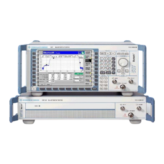
- Page 7 ® ® R&S CBT and R&S CBT 32 ® This manual describes two different models of the Bluetooth Communication tester R&S CBT. • ® Model R&S CBT is equipped with an LC display and provides front panel keys, softkeys and ®...
- Page 8 EC Certificate of Conformity Certificate No.: 2008-06 This is to certify that: Equipment type Stock No. Designation CBT32 1153.9000.32 Bluetooth Tester 2HU 1153.9000.35 Bluetooth Tester 4HU CBT-B41 1170.3406.02/.05 Audio Generator and Analyzer CBT-B42 1170.3706.03 Digital Audio Interface CBT-B55 1170.3006.02 EDR Extension complies with the provisions of the Directive of the Council of the European Union on the approximation of the laws of the Member States - relating to electrical equipment for use within defined voltage limits...
-
Page 9: Basic Safety Instructions
Basic Safety Instructions Always read through and comply with the following safety instructions! All plants and locations of the Rohde & Schwarz group of companies make every effort to keep the safety standards of our products up to date and to offer our customers the highest possible degree of safety. Our products and the auxiliary equipment they require are designed, built and tested in accordance with the safety standards that apply in each case. - Page 10 Basic Safety Instructions Tags and their meaning The following signal words are used in the product documentation in order to warn the reader about risks and dangers. indicates a hazardous situation which, if not avoided, will result in death or serious injury.
- Page 11 Basic Safety Instructions Electrical safety If the information on electrical safety is not observed either at all to the extent necessary, electric shock, fire and/or serious personal injury or death may occur. 1. Prior to switching on the product, always ensure that the nominal voltage setting on the product matches the nominal voltage of the AC supply network.
- Page 12 Basic Safety Instructions 14. Use suitable overvoltage protection to ensure that no overvoltage (such as that caused by a bolt of lightning) can reach the product. Otherwise, the person operating the product will be exposed to the danger of an electric shock. 15.
- Page 13 Basic Safety Instructions Repair and service 1. The product may be opened only by authorized, specially trained personnel. Before any work is performed on the product or before the product is opened, it must be disconnected from the AC supply network.
-
Page 14: Informaciones Elementales De Seguridad
Informaciones elementales de seguridad 2. Handles on the products are designed exclusively to enable personnel to transport the product. It is therefore not permissible to use handles to fasten the product to or on transport equipment such as cranes, fork lifts, wagons, etc. The user is responsible for securely fastening the products to or on the means of transport or lifting. - Page 15 Informaciones elementales de seguridad Se parte del uso correcto del producto para los fines definidos si el producto es utilizado conforme a las indicaciones de la correspondiente documentación del producto y dentro del margen de rendimiento definido (ver hoja de datos, documentación, informaciones de seguridad que siguen). El uso del producto hace necesarios conocimientos técnicos y ciertos conocimientos del idioma inglés.
- Page 16 Informaciones elementales de seguridad Palabras de señal y su significado En la documentación del producto se utilizan las siguientes palabras de señal con el fin de advertir contra riesgos y peligros. PELIGRO identifica un peligro inminente con riesgo elevado que provocará...
- Page 17 Informaciones elementales de seguridad Seguridad eléctrica Si no se siguen (o se siguen de modo insuficiente) las indicaciones del fabricante en cuanto a seguridad eléctrica, pueden producirse choques eléctricos, incendios y/o lesiones graves con posible consecuencia de muerte. 1. Antes de la puesta en marcha del producto se deberá comprobar siempre que la tensión preseleccionada en el producto coincida con la de la red de alimentación eléctrica.
- Page 18 Informaciones elementales de seguridad 12. Si un producto se instala en un lugar fijo, se deberá primero conectar el conductor de protección fijo con el conductor de protección del producto antes de hacer cualquier otra conexión. La instalación y la conexión deberán ser efectuadas por un electricista especializado. 13.
- Page 19 Informaciones elementales de seguridad 5. Ciertos productos, como p. ej. las instalaciones de radiocomunicación RF, pueden a causa de su función natural, emitir una radiación electromagnética aumentada. Deben tomarse todas las medidas necesarias para la protección de las mujeres embarazadas. También las personas con marcapasos pueden correr peligro a causa de la radiación electromagnética.
- Page 20 Informaciones elementales de seguridad 6. En caso de falta de estanqueidad de una celda, el líquido vertido no debe entrar en contacto con la piel ni los ojos. Si se produce contacto, lavar con agua abundante la zona afectada y avisar a un médico.
-
Page 21: Customer Information Regarding Product Disposal
Customer Information Regarding Product Disposal The German Electrical and Electronic Equipment (ElektroG) Act is an implementation of the following EC directives: 2002/96/EC on waste electrical and electronic equipment (WEEE) and • 2002/95/EC on the restriction of the use of certain hazardous substances in •... - Page 22 QUALITÄTSZERTIFIKAT CERTIFICATE OF QUALITY CERTIFICAT DE QUALITÉ Sehr geehrter Kunde, Dear Customer, Cher Client, Sie haben sich für den Kauf eines you have decided to buy a Rohde & vous avez choisi d‘acheter un produit Rohde & Schwarz-Produktes ent- Schwarz product. You are thus as- Rohde &...
-
Page 23: Customer Support
Customer Support Technical support – where and when you need it For quick, expert help with any Rohde & Schwarz equipment, contact one of our Customer Support Centers. A team of highly qualified engineers provides telephone support and will work with you to find a solution to your query on any aspect of the operation, programming or applications of Rohde &... - Page 24 Address List Headquarters, Plants and Subsidiaries Locations Worldwide Headquarters Please refer to our homepage: www.rohde-schwarz.com Sales Locations ROHDE&SCHWARZ GmbH & Co. KG Phone +49 (89) 41 29-0 ◆ Mühldorfstraße 15 · D-81671 München Fax +49 (89) 41 29-121 64 Service Locations ◆...
-
Page 25: New Features
® R&S New Features What’s New in this Revision… ® This operating manual describes version V5.00 and higher of the R&S CBT software. Compared to the previous version V4.61, this new firmware provides the extensions and improvements listed below. New Features Description Refer to... - Page 26 ® Abbreviations R&S Frequently Used Abbreviations Asynchronous connection-less link Audio frequency Att. Attenuation BD_ADDR Bluetooth device address Bit error rate Chan. Channel Center Cyclic redundancy check Device DEVM Differential Error Vector Magnitude Data high rate (packets) Disp. Display Mode Device under test Enhanced Data Rate Ext.
-
Page 27: Table Of Contents
R&S CBT Contents of Chapter 1 Contents 1 Preparation for Use..................... 1.1 Front View (R&S CBT)........................1.2 Rear View (R&S CBT) ........................1.7 Front View (R&S CBT 32).........................1.9 Rear View (R&S CBT 32) ........................1.10 Putting the Instrument into Operation ..................1.12 Unpacking the Instrument ......................1.12 Setting up the Instrument .......................1.12 Bench Top Operation....................1.12 ®... - Page 28 www.valuetronics.com...
-
Page 29: Preparation For Use
R&S CBT Front View (R&S CBT) 1 Preparation for Use ® This chapter describes the controls and connectors of the R&S CBT and gives all information that is necessary to put the instrument into operation and connect external devices. Notes on the update of the ®... -
Page 30: Front View (R&S Cbt)
Front View (R&S CBT) R&S CBT Front View (R&S CBT) ® The front panel of the R&S CBT consists of the VGA display with the softkey area (left side) and the hardkey area (right side, see Fig. 1-1). Brief explanations on the controls and connectors of the hardkey area and the rear panel can be found on the next pages. - Page 31 R&S CBT Front View (R&S CBT) Selection of the most important CBT functions via menus Data input ® Fig. 1-2 R&S CBT front view – hardkeys FUNCTION Operating Manual Fast access to the most important menus: FUNCTION Chap. 4 MENU SELECT Menu overview and selection DATA File manager...
- Page 32 Front View (R&S CBT) R&S CBT System Control Rotary knob: Variation of numeric values and group selection in popup menus ® Fig. 1-3 R&S CBT front view – hardkeys SYSTEM Operating Manual System control: SYSTEM Chap. 4 Displays online help HELP SETUP Instrument settings...
- Page 33 R&S CBT Front View (R&S CBT) Extended editor and instrument control functions ® Fig. 1-4 R&S CBT front view – hardkeys CONTROL Operating Manual Extended control functions: CONTROL Chap. 3 Clears the complete editor string Deletes the character to the left of the cursor (back space) Changes between insertion and overwriting in the editor...
- Page 34 Front View (R&S CBT) R&S CBT AF input and output connectors RF input/output connector ® Fig. 1-5 R&S CBT front view connectors AF connectors Operating Manual Connectors for audio signals: Chapter 8, SPEECH CODEC IN Speech encoder input "Hardware SPEECH CODEC OUT Speech decoder output connectors"...
-
Page 35: Rear View (R&S Cbt)
R&S CBT Rear View (R&S CBT) Rear View (R&S CBT) ® The rear panel of the R&S CBT contains the mains power switch and connectors for the power supply, interfaces and input/output signals. 100 ... 240 VAC 50 .. 60 Hz 220 VA F1 / F2: IEC 127 T3,15 H / 250 V... -
Page 36: Reference Frequency
Rear View (R&S CBT) R&S CBT Ch. 1, "Connecting an External Connector for external keyboard: Keyboard" USB connector Ch. 8, "Hardware Interfaces” Caution! Never connect an external mass storage device, e.g. a USB memory stick, to the USB connector, because this may cause a system crash and even damage the instrument software. -
Page 37: Front View (R&S Cbt 32)
R&S CBT Front View (R&S CBT 32) Front View (R&S CBT 32) ® The front panel of the R&S CBT 32 contains a green LED indicating whether the instrument is power- supplied and the AF and RF connectors. ® Fig. 1-7 R&S CBT 32 front view Power LED Operating Manual... -
Page 38: Rear View (R&S Cbt 32)
Rear View (R&S CBT 32) R&S CBT Rear View (R&S CBT 32) ® The rear panel of the R&S CBT 32 contains the mains power switch and connectors for the power sup- ply, interfaces and input/output signals. 100 ... 240 V AC 50 ... - Page 39 R&S CBT Rear View (R&S CBT 32) Ch. 1, "Connecting an External Connector for external keyboard Keyboard" (for service purposes): Ch. 8, "Hardware Interfaces” USB connector Caution! Never connect an external mass storage device, e.g. a USB memory stick, to the USB connector, because this may cause a system crash and even damage the instrument software.
-
Page 40: Putting The Instrument Into Operation
Putting the Instrument into Operation R&S CBT Putting the Instrument into Operation ® This section describes the basic steps to be taken when setting up the R&S CBT for the first time. Caution: Please make sure to observe the instructions of the following sections so that you cannot cause damage to the instrument or endanger people. -
Page 41: Mounting The Instrument In A Rack (R&Scbt 32)
R&S CBT Putting the Instrument into Operation • Horizontal position, standing on the feet. • Model R&S ® CBT 32: Mounted in a 19" rack (see next section). • Model R&S ® CBT: For applications in the laboratory or on a work bench, it is recommended that the support feet on the bottom of the instrument be extended. -
Page 42: Connecting The Instrument To The Ac Supply
Putting the Instrument into Operation R&S CBT Connecting the Instrument to the AC Supply ® The R&S CBT may be connected to one-phase AC supplies with nominal voltages ranging from 100 V to 240 V and nominal frequencies ranging from 50 Hz to 60 Hz (see inscription on the rear panel and data sheet). -
Page 43: Switching Off The Instrument
R&S CBT Putting the Instrument into Operation Displays in startup The display windows of the startup menu provide information on menu • The startup procedure (Process) • Instrument model, serial number and version of the R&S ® CBT base software (Info). •... -
Page 44: How To Ensure Emc
Putting the Instrument into Operation R&S CBT ® have been stored. The R&S CBT is ready for being turned off at the mains switch. The Store Settings key is inactive and the message You may now switch off the instrument at the rear panel is displayed. -
Page 45: Connecting The R&S Cbt To The Test Setup
R&S CBT Connecting the R&S CBT to the Test Setup Connecting the R&S CBT to the Test Setup Warning: Connect external devices and peripherals only when the instrument is switched off. Otherwise, future errors cannot be excluded. Connecting a Controller ®... - Page 46 Connecting the R&S CBT to the Test Setup R&S CBT The GPIB bus parameters are set via remote control. In the default GPIB Bus configuration the CBT accepts commands from either the GPIB or COM 1 Configuration ® (Model R&S CBT 32) interface.
-
Page 47: Connecting An External Keyboard
R&S CBT Connecting the R&S CBT to the Test Setup After selection of a serial interface, the transmission parameters must be set COM configuration ® to comply with the parameters of the addressed device. This is done in the (Model R&S CBT) Comm. -
Page 48: Connecting A Monitor
Connecting the R&S CBT to the Test Setup R&S CBT The keyboard language can be changed in the Misc. tab of the Setup menu Language assignment ® ® (Model R&S CBT) (model R&S CBT): To open the Setup – Misc. tab press the SETUP key at the front of the instrument and activate the Misc. -
Page 49: Connecting A Printer
R&S CBT Connecting the R&S CBT to the Test Setup Connecting a Printer A printer can be connected via the 25-contact parallel interface LPT at the rear of the instrument (recommended) or the serial interface COM 1. For the interface description see section "Hardware Interfaces" in Chapter 8. The printer type and port must be set in the Print tab of the Setup menu: Printer selection ®... -
Page 50: Software Update And Version Management
Software Update and Version Management R&S CBT Software Update and Version Management ® The R&S CBT is delivered with the latest firmware version available. New firmware can be easily installed via the GPIB interface/connector on the rear panel of the instrument. Installation of new firmware versions and the use of different applications and versions on the same instrument is made easier by the following tools: •... - Page 51 R&S CBT Software Update and Version Management ® ® The R&S Remote Service Tool can communicate with the R&S CBT via the Connecting the ® GPIB (IEEE 488) or a RS-232 interface. It is recommended to use the GPIB R&S interface, connecting the GPIB cable to the IEEE 488 / IEC 625 connector on the rear panel of the instrument.
- Page 52 Software Update and Version Management R&S CBT The software version is copied to the internal drive c:\internal\install of your ® R&S CBT. In addition, a text file named Versions.new (see section File Versions.new on p. 1.29 ff.) is generated and copied to the same directory. With default installation options (see figure above), the following happens after the file transfer is completed: •...
- Page 53 R&S CBT Software Update and Version Management Copying files To transfer a file from the CBT to the PC or vice versa… ® 1. Switch on and start up your R&S CBT. 2. Select Applications – File Transfer from the menu bar of the Remote Service Tool.
- Page 54 Software Update and Version Management R&S CBT 5. Right-click to open a context menu and either copy or close the file. Remote control of You can use the Remote Service Tool to transfer remote control commands or ® the R&S CBT command scripts to be executed on the R&S CBT.
- Page 55 R&S CBT Software Update and Version Management Menu Command Function ® File Transfer Transfer of data between a PC and the R&S CBT. This command activates an additional FileCtrl menu to create directories, copy or delete files. See application examples Copying files and Extracting screenshots above.
-
Page 56: Remote Control Of The R&S Cbt
Software Update and Version Management R&S CBT Remote Control of the R&S CBT The remote control screen transfers remote control commands or command scripts to be executed on ® the R&S CBT; see application example on p. 1.26. It is opened by Remote control of the R&S CBT clicking Application –... -
Page 57: File Versions.new
R&S CBT Software Update and Version Management While the remote control screen is active, an additional Cmd Ctrl menu is available: Table 2 Overview of Cmd Ctrl menu in the Remote Service Tool Menu Command Function Filename… Calls up an Open File dialog to define the name and location of a log file containing Cmd Ctrl all executed commands and device responses. -
Page 58: R&S Cbt Versionmanager
Software Update and Version Management R&S CBT The information in the versions.new file must be unambiguous: Only one Restrictions software configuration with 1 base system software can be installed at once. Alternatively, the file may list several network options to be combined with an already installed, compatible base system version. - Page 59 R&S CBT Software Update and Version Management Activate other software opens a list of all firmware configurations stored on Activate other ® the R&S CBT hard disk except the current configuration. Therefore, this software (optional) function is not available if the hard disk contains only a single configuration (to retrieve information, List software can be used instead).
- Page 60 Software Update and Version Management R&S CBT Delete the current firmware configuration. Delete ® If the active firmware configuration is deleted, the R&S CBT asks which of the remaining versions shall be activated: Activate Activate the current firmware configuration. Install software... Install software... opens a list of all installation versions available on internal storage c:\internal\install Install.
- Page 61 R&S CBT Software Update and Version Management ® Lack of disk space: Before installing the next software version, the R&S CBT checks whether there is enough disk space on the hard disk. If not, the following dialog is displayed: Delete the current version and return back to the Delete previous screen.
- Page 62 Software Update and Version Management R&S CBT ® Exit closes the VersionManager and resumes the R&S CBT start-up Exit procedure. Delete non volatile ram deletes all entries stored in the non volatile ram of Delete non volatile ® ® the R&S CBT.
- Page 63 R&S CBT Software Update and Version Management During operation, the VersionManager can generate two different types of Error and notify messages: message • Error messages indicating that an action could not be successfully performed are displayed in yellow boxes. All error messages with possible reasons and remedial actions are explained in Chapter 9.
- Page 64 www.valuetronics.com...
- Page 65 R&S CBT Contents of Chapter 2 Contents 2 Getting Started ....................2.1 A Short Tutorial on R&S CBT Operation ..................2.2 Condensed Operating Instructions...................2.2 Accessing and Closing Menus ....................2.2 Using Dialog Elements in the Menus ..................2.3 Startup of the R&S CBT ........................2.4 RF Non Signalling Measurements ....................2.8 Preparing a Bluetooth Device Test ....................2.12 Signalling Mode ..........................2.14...
- Page 66 www.valuetronics.com...
-
Page 67: Getting Started
R&S CBT A Short Tutorial on R&S CBT Operation 2 Getting Started ® The following chapter presents a sample session with the Bluetooth communication tester R&S CBT. It is intended to provide a quick overview of the function groups RF Non Signalling, Bluetooth Non Signal- ling and Bluetooth Signalling and to lead through the most common tests which are performed on Blue- tooth devices. -
Page 68: A Short Tutorial On R&S Cbt Operation
A Short Tutorial on R&S CBT Operation R&S CBT A Short Tutorial on R&S CBT Operation The principles of manual operation – controls, operating menus, dialog elements and measurement control – are discussed in Chapter 3 of the complete operating manual. Below you will find some essen- tials for first time users. -
Page 69: Using Dialog Elements In The Menus
R&S CBT A Short Tutorial on R&S CBT Operation The Connect. Control softkey is displayed in the top right position of each measurement menu. Press this softkey to open a popup menu and define the output signals, configure the measurement trigger and the analyzer and select many network-specific settings. -
Page 70: Startup Of The R&S Cbt
Startup of the R&S CBT R&S CBT Startup of the R&S CBT ® This section describes how you can customize the R&S CBT and perform simple RF measurements. As a prerequisite for starting the session, the instrument must be correctly set up and connected to the AC power supply as described in Chapter 1. - Page 71 R&S CBT Startup of the R&S CBT Additional Information... Alternative Settings and Measurements ... on Step 1 Mains switch on the rear panel Chapter 1 When the mains switch at the rear is set to the O position, the ® The R&S CBT is automatically complete instrument is disconnected from the power supply...
- Page 72 Startup of the R&S CBT R&S CBT Step 4 Press the SETUP key to access general SETUP device settings. Press the Time hotkey to switch over to the Time tab of the Setup menu. Step 5 The Time tab of the Setup menu displays the current time zone, time and date.
- Page 73 R&S CBT Startup of the R&S CBT Additional Information... Alternative Settings and Measurements ... on Step 4 Softkeys and hotkeys Chapter 3 of the complete Softkeys and hotkeys are activated by pressing the associ- operating manual ated keys on both sides and across the bottom of the display. The general purpose of softkeys is to provide settings, control the generator and the measurements.
-
Page 74: Rf Non Signalling Measurements
RF Non Signalling Measurements R&S CBT RF Non Signalling Measurements In the RF Non Signalling mode, you can generate a modulated RF signal and measure the power of an RF signal with definite frequency characteristics. No specific device under test is needed for the meas- urement example reported in this section. - Page 75 R&S CBT RF Non Signalling Measurements Additional Information... Alternative Settings and Measurements ... on Step 1 Menu Select menu Chapter 4 of the complete The Menu Select menu shows all function groups installed on operating manual ® your R&S CBT. If a function group is selected the available The RF, Bluetooth Non Signalling test modes and measurement menus are indicated.
- Page 76 RF Non Signalling Measurements R&S CBT Step 3 Press the Connect. Control softkey and use the Generator hotkey to open the Generator tab. The Generator tab controls the RF genera- tor and defines the Frequency and Modula- tion of the generated RF signal. Press once to select the Generator soft- key.
- Page 77 R&S CBT RF Non Signalling Measurements Additional Information... Alternative Settings and Measurements ... on Step 3 Generator control and generator settings Ch. 4 and Ch. 5 The state of the RF generator is shown in the Generator TX To access the essential generator softkey.
-
Page 78: Preparing A Bluetooth Device Test
Preparing a Bluetooth Device Test R&S CBT Preparing a Bluetooth Device Test This section describes the steps that are necessary to prepare a Bluetooth device and connect it to the ® R&S CBT. We assume that you have already switched on the instrument, booted the software and performed a reset as described in section Startup of the R&S CBT on p. - Page 79 R&S CBT Preparing a Bluetooth Device Test Additional Information... Alternative Settings and Measurements ... on Step 2 Data sheet and chapter 4 of the complete operating manual, section RF Con- nector RF connection of the device A high-quality cable should be used for this connection, ideally with an attenuation of less than 0.5 dB.
-
Page 80: Signalling Mode
Signalling Mode R&S CBT Signalling Mode ® In the Signalling mode the R&S CBT first transmits an inquiry signal to detect connectable Bluetooth devices within its domain. From the list of devices compiled during this stage, you can select one target ®... - Page 81 R&S CBT Signalling Mode Additional Information... Alternative Settings and Measurements ... on Step 1 Master signal Chapter 4 of the complete ® operating manual Once a connection has been set up (see below), the R&S CBT and the DUT represent a Bluetooth piconet where the The master signalling parameters ®...
- Page 82 Signalling Mode R&S CBT Step 3 Press the Connect Testmode softkey. The Connected (Paging) tab is displayed. As soon as the connection is estab- lished, the Connection (Connected) tab is displayed (by default, this tab is closed automatically after a short while, but you can reopen it by pressing the Connect.
- Page 83 R&S CBT Signalling Mode Additional Information... Alternative Settings and Measurements ... on Step 3 Paging state Chapter 4 of the complete ® operating manual In the Paging state, the R&S CBT attempts to connect to a selected device. The header message Connecting to Device See section Signalling Control: is displayed in the Connection Control menu.
-
Page 84: Power Measurements
Signalling Mode R&S CBT Power Measurements You can call up all measurement menus in Bluetooth Signalling mode from the Menu Select menu. Once a measurement menu is opened, you can use hotkeys to switch over to any of the other meas- urements. - Page 85 R&S CBT Signalling Mode Additional Information... Alternative Settings and Measurements ... on Step 1 Power menu Chapter 4 of the complete By default the diagram in the Power menu shows the burst operating manual power within one timeslot with a length of 625 bits. You can section Power Measure-...
- Page 86 Signalling Mode R&S CBT Step 3 Press the Marker/Display softkey twice to toggle to the Display/Marker hotkey bar. Press the Time Scale Start hotkey to modify the x-axis and view the rising edge of the burst. The whole display range is shifted, how- ever, the total span remains unchanged.
- Page 87 R&S CBT Signalling Mode Additional Information... Alternative Settings and Measurements ... on Step 3 Softkeys and Hotkeys Chapter 4 of the complete operating manual The functionality of each softkey on the right side is extended by hotkeys assigned to the softkeys. These hotkeys are dis- Analyzer Level controls the level played across the hotkey bar below the diagram when the in the RF input signal path and the...
-
Page 88: Modulation Measurements
Signalling Mode R&S CBT Step 6 Press ESCAPE to close the Power Con- ESCAPE figuration menu and return to the main menu. The trace is now continuously measured and updated in the display. With the display mode Maximum, trace values will be re- placed only if a current measured value at a particular test point exceeds all values measured previously. -
Page 89: Chapter 4 Of The Complete Operating Manual
R&S CBT Signalling Mode Out-of-tolerance power measurements If a power measurement is out of tolerance, please ensure that the attenuation of any cables and/or ® antenna couplers used is taken into account by the R&S CBT. If tight limits to the nominal and peak burst power are set, even a small attenuation can result in an out-of-tolerance measurement. -
Page 90: Spectrum Measurements
Signalling Mode R&S CBT Spectrum Measurements To switch over to the Spectrum measurement, you can again use the hotkey bar. Step 1 Press the Menus softkey to display the measurement groups available in the hotkey bar. Press the Spectrum hotkey to open the Spectrum menu. - Page 91 R&S CBT Signalling Mode Additional Information... Alternative Settings and Measurements ... on Step 1 Spectrum measurement settings Chapter 4 of the complete The Bluetooth conformance specification stipulates different operating manual test settings for the different Spectrum measurement applica- The different Spectrum applica- tions: tions, the test requirements, and •...
-
Page 92: Receiver Quality Measurements
Signalling Mode R&S CBT Receiver Quality Measurements ® To test the Receiver Quality the R&S CBT transmits a bit sequence that the DUT will demodulate and ® loop back to the tester. The R&S CBT compares the bits received with those sent and can thus calcu- ®... - Page 93 R&S CBT Signalling Mode Additional Information... Alternative Settings and Measurements ... on Step 1 Loopback test mode Chapter 4 of the complete ® operating manual In a loopback test, the R&S CBT transmits normal baseband packets. The DUT (acting as a Bluetooth slave) decodes the See section Behavior of the DUT received packets and sends back the payload using the same (Connection Control –...
- Page 94 www.valuetronics.com...
- Page 95 R&S CBT Contents of Chapter 3 Contents 3 Manual Operation....................3.1 Controls.............................3.1 Rotary Knob..........................3.2 Front Panel Keys ........................3.2 Softkeys............................3.2 Hotkeys ............................3.3 Operating Menus ..........................3.4 Measurement Menus .......................3.4 Graphical Measurement Menus ....................3.6 Popup Menus ...........................3.7 Operation of Popup Menus ....................3.8 Dialog Elements in the Menu ......................3.9 Input Fields..........................3.9 Input of Numbers ......................3.9 Input of alphanumerical characters................3.11...
- Page 96 www.valuetronics.com...
-
Page 97: Manual Operation
R&S CBT Controls 3 Manual Operation ® This chapter provides a survey of the R&S CBT's operating concept. It includes a description of the basic menu types, the selection and setting of parameters, and a general discussion of measurement ® control. -
Page 98: Rotary Knob
Controls R&S CBT Rotary Knob The rotary knob can be used in two different ways: • It is turned to select entries in list fields and tables and to vary (increment/decrement) numerical and alphanumerical entries. • It is pressed to expand or compress table sections (thus replacing the ON/OFF key), to expand pull-down lists, to open auxiliary input fields, and to confirm numerical entries or selections (thus replacing the ENTER key). -
Page 99: Hotkeys
R&S CBT Controls The softkey is a measurement control softkey (main softkey) indicating the measurement state (RUN, OFF, HLT). A yellow triangle indicates that a popup menu providing configurations can be opened with the softkey (press once for selection, a second time for opening the popup). A measurement can be started and aborted with the ON/OFF key (i.e. -
Page 100: Operating Menus
Operating Menus R&S CBT Operating Menus ® The R&S CBT offers a large variety of operating modes and applications. To ensure quick and easy operation, uniform menus have been implemented. They can be divided into three types: Measurement menu Offers the most important settings controlling a measurement and displays the main results. - Page 101 R&S CBT Operating Menus Remote control via GPIB (IEEE)-bus Remote debug mode (activated in the Setup – Remote tab) • The function group is indicated to the left of the operating mode: RF measurements Bluetooth measurements The Connect. Control softkey is located to the right of the header of each General settings measurement or graphical measurement menu.
-
Page 102: Graphical Measurement Menus
Operating Menus R&S CBT Popup boxes are associated with all hotkeys that require a selection or input of Popup box parameters. These popup boxes are operated like input fields in the measurement menus (input of numbers and characters) or list fields (selection from a range of alternative settings). -
Page 103: Popup Menus
R&S CBT Operating Menus Popup Menus Popup menus extend the functionality of a measurement menu. They are assigned to the configuration softkey Connect. Control as well as to all measurement control softkeys in a measurement menu that are marked by a yellow triangle at the bottom right. They may be divided into several tabs that are selected via hotkeys in the measurement menu. -
Page 104: Operation Of Popup Menus
Operating Menus R&S CBT Operation of Popup Menus The following table provides an overview of the operation of popup menus. Table 3-1 Operation of popup menus Action Operation via keys Open menu Press the softkey twice (selection plus opening of menu), press only once in the case of Connect. -
Page 105: Dialog Elements In The Menu
R&S CBT Dialog Elements in the Menu Dialog Elements in the Menu This section describes the various types of dialog fields and the procedure for the input of values and parameters. In many input or select field types, a selection made must be confirmed using the ENTER key. The cursor can be freely shifted over these fields;... - Page 106 Dialog Elements in the Menu R&S CBT individual digits varied without restriction. Incrementing a “9“ produces 0 and causes the next higher digit to be incremented by 1. The editor behaves analogously when a “0“ is decremented. An Enter symbol at the bottom right of the input field indicates that ®...
-
Page 107: Input Of Alphanumerical Characters
R&S CBT Dialog Elements in the Menu Error message during input If the value defined in the input field is too high or too low, a window with the error message „<numerical value> is out of range. <permissible maximum value> is limit.“ will appear together with three buttons: Accept Permissible maximum value accepted for input... - Page 108 Dialog Elements in the Menu R&S CBT The most important possible inputs using the rotary knob or the digital keys are described in the following. Activating the input field and auxiliary editor To activate the input field press the associated softkey. If the softkey is assigned to a panel with several controls, use the cursor key to select the desired input field.
-
Page 109: Select Fields In Popup Menus
R&S CBT Dialog Elements in the Menu In insert mode, the cursor appears in the input field. Use the (backspace) key to delete the character to the left of the cursor. Use the (delete) key to delete the inversely displayed character (in overwrite mode). - Page 110 Dialog Elements in the Menu R&S CBT Pull-down list fields are compressed into one line in the popup menu. Press the associated softkey (if available) or use the cursor keys to select the list. Press ENTER or the rotary knob to expand the list (expand in upward or downward direction depending on the space available).
-
Page 111: Measurement Control
R&S CBT Measurement Control Measurement Control ® This section gives a brief survey of the R&S CBT’s measurement control using the function group RF Non Signalling as an example. This includes a discussion of the different measurement modes and measured quantities. Settings and measurement parameters frequently encountered are explained from a general point of view. -
Page 112: Configurations
Measurement Control R&S CBT Configurations ® The R&S CBT offers a wide range of settings for input and output signals and measurements. Configurations either refer to the whole function group (Connection Control) or to a particular measurement. The Connect. Control softkey is located on the right side of the title bar of each Connection measurement and graphical measurement menu. - Page 113 R&S CBT Measurement Control Table 3-5 Measurements in Bluetooth function group Measurement Functionality Overview Indication of the scalar Power, Modulation, and Receiver Quality results and display of the most important signalling parameters. Measurement of the transmitter output power of the Bluetooth DUT as a function of time with Power –...
-
Page 114: General Settings
Measurement Control R&S CBT ® Table 3-6 Measurements in function group Audio (with option R&S CBT-B41) Measurement Function Generates a single-tone sinusoidal audio signal and measures the DC and AC voltage and Analyzer/Generator the Total Harmonic Distortion and Noise of a single-tone audio signal. Generates a composite audio signal consisting of up to 20 individual fixed-frequency tones Multitone with configurable frequency and level. - Page 115 R&S CBT Measurement Control default mode in remote control is Single Shot (perform one measurement and retrieve results). For measurements providing a limit check, two stop conditions can be selected: Stop Condition The measurement is performed according to its repetition None mode, regardless of the measurement results.
- Page 116 Measurement Control R&S CBT no. n – 1 and Current trace no. n according to: > Curr Equation 3-2 The formulas hold for n = 1 where the average trace becomes equal to the current trace (statistics off). Scalar quantities are averaged in analogy to Average traces.
- Page 117 ® R&S Contents of Chapter 4 Contents 4 Functions and their Application................. 4.1 Startup Menu.............................4.1 On-Screen Help (HELP Key) ......................4.2 Reset of Instrument Settings (RESET Key) ...................4.3 Print Menu (PRINT Menu) ........................4.4 Menu Select............................4.6 Popup Menu Setup ...........................4.8 Printer Settings (Setup – Print)....................4.8 Remote-control Settings (Setup –...
- Page 118 ® Contents of Chapter 4 R&S Overview of the Function Group.....................4.45 Measurement Control..................4.46 Selecting the Application .................4.47 Application-Specific Settings ................4.47 Measurement Results ....................4.48 Measurement Configurations (Overview Configuration) ..........4.49 Measurement Control (Overview Configuration – Control) ......4.50 Analyzer Settings (Overview Configuration – Analyzer)........4.51 BER Levels (Overview Configuration –...
- Page 119 ® R&S Contents of Chapter 4 Connection Control in Connected State..............4.137 Connection Control in Test Mode (Test Mode) ............4.139 Connection Control in Sniff State ................4.143 Connection Control in Hold State................4.144 Connection Control in Park State................4.145 Connection Control in Audio State ................4.147 Signal of the R&S CBT (Connection Control –...
- Page 120 ® Contents of Chapter 4 R&S Schematic Description of Connector Configurations ..........4.224 Analog Mono Audio....................4.224 Analog Stereo Audio ....................4.225 Digital Stereo Audio ....................4.228 Microphone Test ......................4.229 Earphone / Speaker Test ...................4.231 Audio Link Test ......................4.232 1154.3470.12 I-4.4 www.valuetronics.com...
-
Page 121: Functions And Their Application
® R&S Startup Menu Functions and their Application ® This chapter explains in detail all functions of the R&S CBT and their application. The structure of the chapter is based on the different menu groups of the instrument. It is organized like a typical measurement session including the following stages: 1. -
Page 122: On-Screen Help (Help Key)
® On-Screen Help (HELP Key) R&S The display windows of the startup menu provide information on Displays in the startup menu • The startup procedure (Process). • ® Instrument model, serial number and version of the R&S CBT base software (Info). -
Page 123: Reset Of Instrument Settings (Reset Key)
® R&S Reset of Instrument Settings (RESET Key) Reset of Instrument Settings (RESET Key) The popup window Reset sets the instrument settings in all or some function groups and test modes to their default values. It is opened via the RESET key (CONTROL keypad). Note: A reset of the instrument does not necessarily mean that the current instrument settings ®... -
Page 124: Print Menu (Print Menu)
® Print Menu (PRINT Menu) R&S The Reset button resets all settings in the selected function groups and test modes. Reset A box pops up to confirm the reset. While the reset is performed, the message Reset in progress is displayed. All running measurements are aborted and a connection to a DUT is dropped. - Page 125 ® R&S Print Menu (PRINT Menu) The Print Mode select field permits to specify the data type for the output: Print Mode Copy of the current display in landscape format Screen-Dump (Landscape) An example of a screen-dump copy is shown in a preview to the right of the select field.
-
Page 126: Menu Select
® Menu Select R&S Menu Select The Menu Select menu gives an overview of all available measurements that can be selected and called up directly from the menu. The measurements are arranged in tables showing their hierarchical ® structure. Menu Select appears after termination of the startup procedure of the R&S CBT or after pressing the Menu Select key. - Page 127 ® R&S Menu Select The Hotkey Assign. hotkey activates the assign mode used to assign a softkey to Hotkey the function group, signalling mode and measurement menu currently selected. Assign. The three softkeys of the Menu Select menu belonging to Hotkeys Set 1 have a default assignment.
-
Page 128: Popup Menu Setup
® Popup Menu Setup R&S Popup Menu Setup ® The popup menu Setup contains several tabs used to adapt the R&S CBT to user requirements. The menus are opened by pressing the Setup key. It is possible to change between the tabs by pressing the associated hotkeys. -
Page 129: Remote-Control Settings (Setup - Remote)
® R&S Popup Menu Setup The Header section defines and activates header for the printed page. Header Print the header defined in the Header Text input field when a Print header page is printed. An additional comment for every single page can be defined in the Print popup menu (see p. -
Page 130: Chapter 7, Program Examples
® Popup Menu Setup R&S ® The SCPI Connection section determines the remote-control interface of the R&S SCPI CBT. Connect The following interface settings are available: Auto-detection of the interface, the instruments accepts GPIB + COM1 commands from either the GPIB or COM 1 interface IEEE-bus interface according to IEEE 488 GPIB Serial (RS-232-C) interface COM 1... - Page 131 ® R&S Popup Menu Setup ® CBT if conflicting measurements are run in Determines the behavior of the R&S Local/Remote parallel. Mode: Task Priority Task Priority Management Management On (box checked) All measurements are releasable: A new measurement has priority over a running measurement. All measurements are persistent: A running measurement has priority over a new measurement.
-
Page 132: Remote Debug Mode
® Popup Menu Setup R&S Remote control TRACe:REMote:MODE:FILE ON | OFF Remote Debug Mode The remote debug mode is activated in the Remote tab of the Setup menu; see above. In this mode, the MMI can be used to visualize, monitor, or check the results of measurements controlled via the remote interface. -
Page 133: Serial Interfaces (Setup - Comm.)
® R&S Popup Menu Setup Serial Interfaces (Setup – Comm.) The interface menu (Setup Comm.) defines the transmission parameters of the serial outputs COM 1 and COM 2. S E TU P Fig. 4-8 Interface menu The COM 1 section defines the transmission parameters for the serial interface COM 1 COM 1. -
Page 134: Hardware And Software Options (Setup - Options)
® Popup Menu Setup R&S Hardware and Software Options (Setup – Options) The option menu (Setup Options) provides information on the type of instrument and the installed options, equipment and firmware versions (Software Options, Hardware Options, Hardware Equipment, Firmware Versions). New software options purchased can be enabled in this menu using a code number. - Page 135 ® R&S Popup Menu Setup Software options can be enabled or disabled in the Enable check boxes of the Enabling Software Options table. As all software options are already included in the firmware, software options enabling does not require any re-installation, but only a key code which is supplied with the option.
-
Page 136: Time Settings (Setup - Time)
® Popup Menu Setup R&S The hardware accessories are listed in the Hardware Equipment section. Hardware Equipment / Note: An comprehensive list of the hardware equipment of the instrument is Firmware provided in the Info menu; see p. 4.18. Versions The FW version for the Digital Board (FPGA Digital) and RF Board (FPGA RF) is displayed in the Firmware Versions section. -
Page 137: Acoustic Signal And Keyboard (Setup - Misc.)
® R&S Popup Menu Setup The Time table section sets the current time and its display format: Time Time in the format hours:minutes:seconds hh:mm:ss. Zone Selection of the time zone, Middle European time (Greenwich mean time (GMT) + 1 h) is set by default 12 Hours: 12:00:00 am ... -
Page 138: System Information (Info)
® System Information (Info) R&S ® The Display Settings configures the R&S CBT LC display: Display Settings Selects the brightness of the display. In the High Contrast Display Color setting, the display is darker; the contrasts are enhanced. Screen Save Time Defines a time in minutes after which the display will turn dark if no front panel key is pressed. -
Page 139: Selftest (Maintenance)
® R&S Selftest (Maintenance) Selftest (Maintenance) The Maintenance popup menu, which is accessible via the BASE function group in the Menu Select menu, complements the Info menu (see p. 4.18 above) in providing service information, selftests and correction procedures that are aimed to improve particular measurements. The selftests are primarily intended for production and service purposes and therefore not needed during normal operation of the instrument. - Page 140 ® Selftest (Maintenance) R&S Tests all voltages generated on the RF board and also RF Board measures the actual temperature on the RF board. Digital Board Tests all remaining system voltages, included the voltages generated on the Digital Board. Note: Notice messages after firmware updates In most cases firmware updates don’t affect the accuracy of the measurements.
-
Page 141: Data Handling (Data)
® R&S Data Handling (Data) Data Handling (Data) The Data popup menu, which is opened by pressing the DATA key, saves and recalls configuration files and manages the files in the internal memory that can be used for mass storage. Saving Configurations (Data –... - Page 142 ® Data Handling (Data) R&S Content/Destination toggles between the configuration tree (see Fig. 4-14 above) Content and a view of the directories available for storing the configuration file (*.SAV). The Destination Destination view is analogous to the Arrange tab; see section File Manager (Data –...
-
Page 143: Loading Saved Configurations (Data - Recall)
® R&S Data Handling (Data) Note: A third question mark in the file name extends the auto-increment function so that up to 999 configuration files can be stored. Keep in mind the capacity of the internal hard disk when using this feature. Selecting OK to Save closes the dialog window and stores the inputs made. - Page 144 ® Data Handling (Data) R&S File selection The stored files can be selected from a tree view in the center of the menu. The tree can be expanded and compressed using the roll-key and the ON/OFF key (see Chapter 3, Expanding menu tables). By default, configuration files are stored in the directory INTERNAL\USERDATA\SAVE and with the file names DATA??.SAV, where the question mark is replaced by a current number.
-
Page 145: File Manager (Data - Arrange)
® R&S Data Handling (Data) File Manager (Data – Arrange) The Arrange tab in the Data popup menu manages the files in the internal and external memories that can be used for mass storage. The menu is particularly useful for handling files containing user data such as: •... - Page 146 ® Data Handling (Data) R&S Dir. View/Content toggles between the directory view (see above) and the Fig. 4-16 Dir. View overview of function groups and test modes contained in a configuration file Content (*.SAV). The Content view is available for configuration files only: The Content view shows the path and name of the configuration file and all function groups and test modes contained in the file.
- Page 147 ® R&S Data Handling (Data) • If a directory is selected, no particular information is needed so the softkey reads Rename. It opens a popup window to rename and move the directory by editing the Path and the Directory name. The path can be entered according to DOS conventions, if so desired.
- Page 148 ® Data Handling (Data) R&S ® Before a directory is deleted, the R&S CBT generates a similar warning: Selecting Yes deletes the file or directory; selecting No closes the warning messages without deleting. Remote control MMEMory:DELete <FileName>, [INTernal | EXTernal] MMEMory:RMDir <DirName>, [INTernal | EXTernal] The Make Directory softkey creates a new directory.
-
Page 149: Bluetooth Non Signalling Mode
® R&S Bluetooth Non Signalling Bluetooth Non Signalling Mode This section provides detailed information on function group Bluetooth Non Signalling. In this mode, it is possible to generate an RF signal with Bluetooth specifications, to configure the RF input and output ®... -
Page 150: Rf Generator Panel
® Bluetooth Non Signalling R&S RF Generator Panel The RF Generator panel contains softkeys which allow the configuration of: • The RF Level of the generator • The RF Channel number or Frequency • The RF Generator softkey controls the RF generator and indicates its operating status (ON | OFF). -
Page 151: Generator Modulation Panel
® R&S Bluetooth Non Signalling Remote control SOURCe:RFGenerator:FREQuency:UNIT <Unit> SOURCe:RFGenerator:FREQuency <Frequency> Generator Modulation Panel The Generator Modulation panel contains the softkeys for configuration of the RF generator signal. These softkeys allow the selection of packet type and length of test sequence, configuration of the payload pattern, and setting of the Bluetooth Device address (Master). - Page 152 ® Bluetooth Non Signalling R&S With the EDR options R&S CBT-B55 and R&S CBT-K55 installed, the following packet types are also supported: Header User Payload Timeslots Type (Bytes) (Bytes) (Max) 2-DH1 (E21P) 0 to 54 2-DH3 (E23P) 0 to 367 2-DH5 (E25P) 0 to 679 3-DH1 (E31P)
-
Page 153: Connection Control
® R&S Bluetooth Non Signalling Connection Control The popup menu Connection Control contains three tabs to configure the inputs and outputs of the ® R&S CBT and the respective signals in the function group Bluetooth Non Signalling. The menu group is activated via the softkey Connect. Control to the right of the header of each measurement menu. -
Page 154: Af/Rf Connectors (Connection Control - Af/Rf Connectors)
® Bluetooth Non Signalling R&S The Frequency Offset softkey defines an offset for the frequency set under RF Frequency Channel. The range of the Frequency Offset is such that any intermediate Offset frequency between two RF Channels can be covered. With options R&S CBT-B55/K55 the frequency offset can be set independently for the GFSK and DPSK modulated portions of the generated EDR packets (packet types 2-DH1 to 3-DH5). -
Page 155: Reference Frequency (Connection Control - Sync.)
® R&S Bluetooth Non Signalling Fig. 4-38 Connection Control – RF connectors Reference Frequency (Connection Control – Sync.) The Sync. tab defines the reference signals for synchronization. The settings are analogous to the ones in function group RF Non Signalling; see section Reference Frequency (Connection Control – Sync.). Fig. -
Page 156: Tx Tests In Non Signalling Mode
® Bluetooth Non Signalling R&S TX Tests in Non Signalling Mode In Non Signalling mode, the R&S CBT does not provide any measurement menus. However, with a suitably configured Bluetooth DUT, it is possible to perform non signalling Power and Modulation measurements using the Signaling measurement menus. - Page 157 ® R&S Bluetooth Non Signalling The Packet Timing and Delta Level results are not available in non signalling mode. The same holds for the derived Bursts out of Tol (Tim.) result; see below. Measurement The non signalling measurement provides the Power and Modulation results with results the exceptions listed below.
-
Page 158: Bluetooth Signalling Mode
® Connection Setup R&S Bluetooth Signalling Mode This section provides detailed information on the measurement and configuration menus defined in function group Bluetooth Signalling. It is organized like a typical measurement session including the following stages: • Connection to a device under test (Connection Control – Signalling), •... - Page 159 ® R&S Connection Setup Signalling Description Measurements State possible page ® The R&S CBT transmits a signal to synchronize and try to connect to a – 4.43 Paging known Bluetooth device. From this state, either the Test Mode or the Connected state can be reached.
-
Page 160: Connection Control: Standby State
® Connection Setup R&S Connection Control: Standby State The Connection (Standby) tab provides information on: • The master and slave signal parameters The paging mode • Besides, it activates an inquiry or a connection to a particular Bluetooth device. The Connection (Standby) tab is opened when the function group Bluetooth Signalling is selected, or if a connection is dropped (Stop connection softkey in the Paging state or Detach softkey in the Test ®... -
Page 161: Connection Control: Inquiry State
® R&S Connection Setup ® The table Master Signal indicates important signalling parameters that the R&S Master Signal CBT (acting as a Bluetooth master) uses to inquire and page Bluetooth slaves in its range. These parameters are set in the Master Sig. tab and explained in more detail there (see section Signal of the R&S CBT (Connection Control –... - Page 162 ® Connection Setup R&S • Besides, it contains a softkey (Stop Inquiry) that stops the inquiry and leads back to the Connection (Standby) tab. ® The Connection (Inquiry) tab is opened when an inquiry is attempted from the Standby state. The R&S CBT returns back to the Connection (Standby) tab after the inquiry is completed or deliberately stopped (Stop Inquiry).
-
Page 163: Connection Control: Paging State
® R&S Connection Setup Connection Control: Paging State The Connection (Paging) tab provides information on • The master and slave signal parameters The paging mode • Besides, it allows to stop the connection setup to a particular Bluetooth device (Stop Connect). ®... - Page 164 ® Connection Setup R&S Stop The Stop Connect. softkey stops the connection phase. Connect ® This will return the R&S CBT to the Standby state. Remote control PROCedure:SIGNalling:ACTion SCONnect 1154.3470.12 4.44 www.valuetronics.com...
-
Page 165: Overview Of The Function Group
® R&S Overview of the Function Group Overview of the Function Group The Overview menu displays the essential results of the Power, Modulation and Receiver Quality measurements and provides access to the most important measurement settings. In particular, it ® configures the signal transmitted by the R&S CBT (Master Sig.) and controls the behavior of the Bluetooth DUT in test mode (Slave Sig.). -
Page 166: Measurement Control
® Overview of the Function Group R&S The Overview menu is opened from the Menu Select menu (with associated key at the front of the instrument) and after closing the configuration menu Connection Control - Connection (using the Escape key or automatically after establishing a connection). From the Overview menu, the remaining measurement menus of the function group (Power, Modulation, Receiver Quality) are accessible via hotkeys. -
Page 167: Selecting The Application
® R&S Overview of the Function Group INITiate:RXQuality:BER etc. FETCh:RXQuality:BER? The configuration settings for the Modulation/Power and Receiver Quality Measurement measurements are directly accessible from the Overview menu. They are collected configuration in a common configuration menu that is opened on pressing the measurement control softkey a second time. -
Page 168: Measurement Results
® Overview of the Function Group R&S Analyzer Settings – Measured Channel Analyzer Settings – Measured Frequency Remote control In remote control, the independent settings are accessed by the following POWer:MPR configuration commands: CONFigure:POWer:MPR:CONTrol:STATistics <Statistic_Count> CONFigure:POWer:MPR:CONTrol:REPetition <Repetition>, <Stop_Cond>, <Step_Mode> CONFigure:POWer:MPR:MMODe <Mode> CONFigure:POWer:MPR:FREQuency <Meas_Frequency>... -
Page 169: Measurement Configurations (Overview Configuration)
® R&S Overview of the Function Group The results for the Modulation/Power application are explained in the following Results sections: • The power results Nominal Power, Leakage Power and Peak Power are described in section on p. 4.61. Measurement Results •... -
Page 170: Measurement Control (Overview Configuration - Control)
® Overview of the Function Group R&S The popup menu Overview Configuration is activated by pressing the measurement control softkey in the Overview menu a second time. It is possible to change between the tabs by pressing the associated hotkeys. Measurement Control (Overview Configuration –... -
Page 171: Analyzer Settings (Overview Configuration - Analyzer)
® R&S Overview of the Function Group Receiver Quality The Receiver Quality settings define the scope of the Receiver Quality application in up to 5 different test setups. The meaning of the settings is as explained in section Measurement Control (Receiver Quality Configuration – Control) on p. -
Page 172: Ber Levels (Overview Configuration - Master)
® Overview of the Function Group R&S BER Levels (Overview Configuration – Master) ® The Master tab defines the RF generator level of the R&S CBT at which the Receiver Quality measurement is performed. The settings are identical to the BER settings in the Master tab of the Receiver Quality Configuration menu;... - Page 173 ® R&S Overview of the Function Group The Modulation/Power settings define limits for the Modulation/Power application. Modulation/ The settings are explained in sections Power Limit Values (Power Configuration – Limits) on p. 4.71. and Limit Values (Modulation Configuration – Limits) on p.
-
Page 174: Power Measurements
® Power Measurements R&S Power Measurements The menu group Power comprises the functions for measuring the power of the received RF burst signal as a function of time. The measurement results are displayed in the graphical measurement menu Power, with the popup menu Power Configuration being used for configuration of the measurements. -
Page 175: Test Settings
® R&S Power Measurements Menu Select Menu Select Fig. 4-47 Measurement menu Power Test Settings The basic settings for the Power measurement are directly accessible from the measurement menu via softkey/hotkey combinations. The entry of values is described in section Test Settings on p. - Page 176 ® Power Measurements R&S Remote control INITiate:POWer:RELative ABORt:POWer:RELative STOP:POWer:RELative CONTinue:POWer:RELative FETCh:POWer:RELative:STATus? Pressing the Output Power or Relative Power softkey a second time opens the Measurement configuration popup menu Power Configuration (see page 4.66). In addition, the measurement control softkeys provide hotkeys to define the scope of the measurement. All these settings are described in more detail in section Measurement Control (Power on page 4.67.
- Page 177 ® R&S Power Measurements Remote control PROCedure:PCONtrol:STEP UP PROCedure:PCONtrol:STATe? (query power control state of the DUT) The Power Down hotkey sends a decrease power request to the DUT. This softkey Power can be pressed repeatedly; the resulting power decrease is indicated as Delta Down Power in the output table in the Power measurement menu.
- Page 178 ® Power Measurements R&S Specific Power Settings The settings of the following softkeys are specific to Power measurements. They are not available in the Connection Control menu. The Analyzer Settings softkey determines the RF channels that are being Analyzer monitored within the measurement. The settings are also provided in the Power Settings Configuration menu.
- Page 179 ® R&S Power Measurements The (Pre) Leakage hotkey selects the Start and the Span of the leakage pre-area. (Pre) The leakage pre-area is a time domain before the ramp-up of the burst where the Leakage leakage power is measured; see Fig.
- Page 180 ® Power Measurements R&S The Rel. 1 hotkey switches the delta marker 1 on or off (use the ON/OFF key). The delta marker 1 is represented by the symbol in the test diagram. The marker position (abscissa) is defined in the input field Rel. Marker 1. The marker can be positioned to arbitrary time values.
-
Page 181: Measurement Results
® R&S Power Measurements The Time Scale hotkey defines the x-axis (time) scale of the diagram and the Time measurement range. The entered Start value defines the left edge of the diagram Scale relative to the first bit of the preamble (bit 0); see Fig. - Page 182 ® Power Measurements R&S Parameter line 1|2 Test diagram Output table and output fields Fig. 4-48 Display of measurement results (Output Power) Settings/ Settings and scalar measurement results are indicated in the two parameter lines scalar measure- above and in the table and output fields below the test diagram. ment results parameter line The first parameter line contains the following settings: Maximum expected input level as set in Max.
- Page 183 ® R&S Power Measurements averaging rules in chapter 3) and the maximum and minimum values over all bursts measured so far (Maximum, Minimum) are calculated. Measurements that are not within their limits are indicated with a red background. Average burst power during the carrier-on state. The nominal Nominal Power power is measured as the part of the burst starting at the detected 1...
- Page 184 ® Power Measurements R&S The measurement result is displayed as a continuous measurement curve (trace) in Measurement the test diagram together with the limit lines, markers and the D-line, if activated. curves (arrays) The trace in the Power measurement menu shows the measured burst power (in dB) as a function of time (in bits).
- Page 185 ® R&S Power Measurements Parameter line 1|2 Test diagram Output table and output fields EDR Packet measurement definition Fig. 4-50 Display of measurement results (Relative Power) Settings/ The two parameter lines, showing settings and scalar measurement results, and the output fields, are fully described under Output Power Application (see above). scalar measure- ment results, and Output...
-
Page 186: Measurement Configurations (Power Configuration)
® Power Measurements R&S A red output field and an arrow pointing upwards or downwards indicates that the Limit Check measurement result exceeds the upper or lower limit set in the Limits tab of the Power Configuration menu, see p.4.71. Remote control Settings are read out using the query corresponding to the setting command (setting command with appended question mark). -
Page 187: Measurement Control (Power Configuration - Control)
® R&S Power Measurements Measurement Control (Power Configuration – Control) The Control tab controls the power measurement by defining • The Repetition mode • The Stop Condition for the measurement • The type of measurement curve displayed (Display Mode) • The number of bursts/evaluation periods forming a statistics cycle (Statistic Count) Besides, it configures the graphical diagram by adding or removing the Grid. - Page 188 ® Power Measurements R&S The Repetition mode set in manual control is valid in manual control only. Changing this parameter in manual control does not alter the repetition mode in remote control and vice versa. The default repetition mode in remote control is SINGleshot. Remote control CONFigure:Power:TIME:CONTrol:REPetition CONTinuous | SINGleshot | 1 ...
-
Page 189: Analyzer Settings (Power Configuration - Analyzer)
® R&S Power Measurements <MODE>,1 ... 1000 | OFF CONFigure:Power:RELative:CONTrol <MODE>,1 ... 1000 | OFF The Grid parameter switches the grid in the graphical test diagram on or off. In the Grid default setting, the grid is switched on. Remote control No command, screen configuration only Analyzer Settings (Power Configuration –... - Page 190 ® Power Measurements R&S The current channel is displayed in brackets above the scalar result table in the measurement menu so it is always clear which channel the current results belong to. Measurements are performed only on bursts from the channel Single selected via the Measured Channel hotkey.
-
Page 191: Limit Values (Power Configuration - Limits)
® R&S Power Measurements Bluetooth Measured Channel. No other channels will be measured and displayed. When a Channel is selected, the Frequency is updated to correspond with the selected channel and vice versa. Remote control CONFigure:POWer:TIME:MMODe <Mode> CONFigure:POWer:TIME:MFRequency <Meas_Frequency> CONFigure:POWer:TIME:MFRequency:UNIT <Unit> CONFigure:POWer:RELative:MMODe <Mode>... - Page 192 ® Power Measurements R&S Fig. 4-54 Power Configuration – Limits (Output Power) The table in the Limits tab contains four sets of parameters, which are the limits for the Nominal Power, the Leakage Power, the Peak Power, and the Packet Timing measurement. The four parameter sets are arranged as follows: The Default switch assigns default values to all limit settings of the current Default...
- Page 193 ® R&S Power Measurements (b) Limits: Relative Power Relative Power measurements and results are only available after installation of EDR options (B55/K55) for the R&S CBT. The Limits tab defines tolerances for the GFSK Power (P ), DPSK Power (P ), and the Relative GFSK DPSK...
- Page 194 ® Power Measurements R&S Remote control CONFigure:POWer:RELative:CURRent:LIMit:SCALar:ASYMmetric:UPPer:VALue <GFSK_Power>,<DPSK_Power>,<Relative_Power>, <guard_time> CONFigure:POWer:RELative:CURRent:LIMit:SCALar:ASYMmetric:LOWer:VALue <GFSK_Power>,<DPSK_Power>,<Relative_Power>, <guard_time> CONFigure:POWer:RELative:CURRent:LIMit:SCALar:ASYMmetric:UPPer :ENABle ON | OFF … CONFigure:POWer:RELative:CURRent:LIMit:SCALar:ASYMmetric:LOWer :ENABle ON | OFF … CONFigure:POWer:RELative:CURRent:LIMit:SCALar:ASYMmetric <GFSK_Upp> … <guard_time_low> :COMBined:VALue CONFigure:POWer:RELative:CURRent:LIMit:SCALar:ASYMmetric :COMBined:ENABle ON | OFF … ...etc. 1154.3470.12 4.74 www.valuetronics.com...
-
Page 195: Modulation Measurements
® R&S Modulation Measurements Modulation Measurements The menu group Modulation comprises the functions for measurement of the modulation parameters described below and for matching of the respective tolerance limits. With B55/K55 hardware and software options installed on the CBT, support for Enhanced Data Rate (EDR) packets becomes available, in addition to Basic Rate packets. -
Page 196: Test Settings For The Encoding Measurement
® Modulation Measurements R&S section on p. 4.76. Test Settings for the Encoding Measurement The measurement of these quantities is explained in more detail in section Measurement Results on page 4.80. Two measurement filters with different bandwidths and two different algorithms for averaging are provided; see section Analyzer Settings (Modulation Configuration –... -
Page 197: Calculation Of I/Q Analyzer Diagrams And Phase Difference
® R&S Modulation Measurements To configure your R&S CBT in accordance with the test requirements, R&S CBT configuration 1. Press MENU Select and select the Bluetooth – Signalling – Modulation – Encoding measurement. 2. Reset the Bluetooth Signalling function group (see detailed measurement examples in Chapter 2). - Page 198 ® Modulation Measurements R&S the next block. The S symbol is used as a reference for the first block. The I/Q values can be displayed in three different diagram types (see also section on p. 4.87). I/Q Analyzer DPSK Absolute The absolute I/Q diagrams show the (normalized) I/Q vectors of the S symbol I/Q symbols...
-
Page 199: Measurement Menu (Modulation)
® R&S Modulation Measurements I/Q symbols can be displayed for EDR Bluetooth bursts only. Prerequisites I/Q symbols will not be displayed for any EDR Bluetooth bursts without valid EDR synchronization sequence or less than 50 valid DPSK symbols (excluding the S Moreover, remaining symbols from fractional blocks at the end of the burst are not displayed. - Page 200 ® Modulation Measurements R&S …MODulation:ENCoding…, …MODulation:IQANalyzer:DPSKeying…, …MODulation:PDIFference… subsystems, respectively. The Display/Marker softkey zooms or shifts the graphical display. It is selected by Display pressing the Marker/Display softkey a second time. If pressed once again, the Marker selected Display/Marker softkey changes back to the Marker/Display softkey. The Freq.
-
Page 201: Measurement Results
® R&S Modulation Measurements Measurement Results The values shown in the Modulation measurement menu can be divided into three groups: • Setting values • Scalar measurement results (single values) • Arrays (traces plotted as a function of time) The results are indicated in two parameter lines, the test diagram, an output table plus additional output fields. - Page 202 ® Modulation Measurements R&S Scalar measurement results and settings are indicated in the two parameter lines Settings/ above the test diagram and in the output table below. Scalar results parameter line The first parameter line contains the following settings: Maximum input level set as in Input Level - Mode (see Max.
- Page 203 ® R&S Modulation Measurements calculated while the test is performed with an alternating 01010101 pattern. DPSK only: 99% DEVM The percentage of measured symbols whose DEVM does not exceed a user-defined threshold. The field displays in red when the percentage falls below a user-defined limit. The threshold and percentage values are set in the Modulation Configuration menu;...
- Page 204 ® Modulation Measurements R&S Frequency drift calculation Fig. 4-60 Calculation of Frequency Drift Maximum Drift Rate The maximum of the drift rate anywhere within the packet payload. The drift rate is a function of time; it is an estimate for the first derivative of the frequency drift with respect to time.
- Page 205 ® R&S Modulation Measurements Frequency Stability and DEVM At the baseband level, EDR continues to use the 1.6 kHz slot rate and 1 MHz symbol rate as is used for Basic Rate packets. The 2x and 3x times data rates, relative to Basic Rate packets, are achieved by DPSK encoding of the payload.
- Page 206 ® Modulation Measurements R&S FETCh[:SCALar]:MODulation:DEViation:BATHreshold? CALCulate:MODulation:DEViation:LIMit:MATChing? READ[:SCALar]:MODulation:DPSKeying? CALCulate:SCALar:MODulation:DPSKeying:MATChing:LIMit? The continuous trace in the test diagram for GFSK shows the frequency deviation Traces (arrays) (in kHz) in the packet as a function of time (in bits). The continuous trace in the test diagram for DPSK shows DEVM for each measured symbol as a function of time (in symbols).
- Page 207 ® R&S Modulation Measurements The output in the left half of the menu shows the results of the Modulation Encoding Results measurement. Bit Error Rate Bit Error Rate, ratio of bits received in error to the total number of received bits. Packets with 0 bit errors Percentage of received packets with zero errors.
- Page 208 ® Modulation Measurements R&S Fig. 4-63 I/Q Analyzer DPSK: absolute results (8DPSK modulation) Scalar results The scalar modulation parameters indicated in the output fields on the right side are also shown in the other Modulation applications; see e.g. section Calculation of I/Q on p.
- Page 209 ® R&S Modulation Measurements READ:ARRay:MODulation:IQANalyzer:DPSKeying:IPHASe? etc. READ:ARRay:MODulation:IQANalyzer:DPSKeying:QPHASe? b) Differential results Fig. 4-64 I/Q Analyzer DPSK: differential results ( /4-DQPSK modulation) Scalar results and remote control commands are equal for all diagram types. Diagrams The differential constellation and vector diagrams trace the differential /4-DQPSK or 8DPSK modulation vector in the normalized I/Q plane over a single packet.
-
Page 210: Phase Difference
® Modulation Measurements R&S Scalar results and remote control commands are equal for all diagram types. Diagrams These diagrams trace the differential error vectors in the normalized I/Q plane over a single packet. The amplitude of a symbol in this diagram is the DEVM for the corresponding symbol within the Bluetooth burst. - Page 211 ® R&S Modulation Measurements Menu Select Menu Select Fig. 4-66 Phase difference results Scalar results The scalar results indicated in the output fields below the diagram are also shown in the other Modulation applications; see e.g. section Modulation GFSK, Modulation on p.
- Page 212 ® Modulation Measurements R&S Last phase difference within the EDR synchronization Marker 2 sequence Fig. 2 Phase Difference Graph: Guard Period and Synchronization Sequence CRC and trailer Phase differences are also displayed for “symbols” beyond the end of the Bluetooth symbols EDR burst.
-
Page 213: Measurement Configurations (Modulation Configuration)
® R&S Modulation Measurements Measurement Configurations (Modulation Configuration) The popup menu Modulation Configuration contains three tabs which determine the parameters of the Modulation measurement. The popup menu Modulation Configuration is activated by pressing the Modulation measurement control softkey in the top right of the graphical measurement menu Modulation a second time. By pressing the associated hotkeys, it is possible to change between the tabs. -
Page 214: Analyzer Settings (Modulation Configuration - Analyzer)
® Modulation Measurements R&S Differential Error Vector Magnitude (DEVM) at the decision points Error For details concerning the calculation refer to section Calculation of I/Q Analyzer Diagrams and Phase Difference on p. 4.77. Remote control CONFigure:MODulation:IQANalyzer:DPSKeying:SYMBol:MODE ABS | DIFF | ERR Zoom magnifies the diagram with an equal factor in horizontal and vertical direction, Zoom leaving the center (i.e. - Page 215 ® R&S Modulation Measurements …MODulation:ENCoding…, …MODulation:IQANalyzer:DPSKeying…, …MODulation: PDIFference…. The following settings are not provided in the Power Configuration menu: Filter Bandwidth Selects the resolution bandwidth of the measurement filter used for Modulation measurements. The (default) wide band and the narrow band filter match the two alternative filter settings stipulated in the revised Bluetooth RF test specification.
-
Page 216: Limit Values (Modulation Configuration - Limits)
® Modulation Measurements R&S Limit Values (Modulation Configuration – Limits) The tab Limits defines upper and lower error limits for the results obtained in the Modulation measurement. All relevant quantities are explained in section on p. 4.81. Measurement Results Note that when the EDR options R&S CBT-B55/K55 are installed, the Modulation measurement menu supports the DPSK, Encoding and the I/Q Analyzer applications in addition to GFSK. - Page 217 ® R&S Modulation Measurements The table in the Limits tab provides six parameter sets for Modulation GFSK, defining limits for the Frequency Accuracy, the Frequency Drift, the Maximum Drift Rate, and the Frequency Deviation measurement. Independent limits can be set for the average of the frequency deviation over the whole packet, for its maximum, and for its minimum value.
- Page 218 ® Modulation Measurements R&S Current/ The table sets upper and lower limits for the current measurement and enables or disables the limit check. The limits are set independently for the Current, Average, Average/ Minimum/ Maximum, and Minimum modulation results; see Display Mode setting in section on p.
- Page 219 ® R&S Modulation Measurements must be less than or equal to the Threshold. The DUT passes the test if at least Conformance Limit % of all measured symbols have a DEVM that does not exceed the Threshold. Remote control CONFigure:MODulation:DPSKeying:DEVMagnitude:THReshold[:VALue] CONFigure:MODulation:DPSKeying:CLIMit:ENABLE ON | OFF CONFigure:MODulation: DPSKeying:CLIMit[:VALue] CONFigure:MODulation:IQANalyzer:DPSKeying:DEVMagnitude...
-
Page 220: Spectrum Measurements
® Spectrum Measurements R&S Spectrum Measurements The Spectrum menu group measures the output RF spectrum emissions in the frequency domain. The measurement results are displayed in the graphical measurement menu Spectrum, with the popup menu Spectrum Configuration providing all measurement settings. The Spectrum measurement is to verify that emissions in the Bluetooth operating frequency range are within the limits. - Page 221 ® R&S Spectrum Measurements In the default configuration most of the Spectrum measurement settings comply Performing a with the requirements for the ACP and 20 dB bandwidth test cases in the Bluetooth measurement radio specification. The settings to be made manually are listed below. With a firmware version V4.37 and higher, frequency hopping is automatically disabled while the ACP application is active (equivalent to Connection Control –...
-
Page 222: Frequency Range Application
® Spectrum Measurements R&S signal will generally not terminate the connection. The previous Supervision Timeout is restored after another TX or RX measurement is selected. Frequency Range Application The Frequency Range application (SPECtrum:FRANge…) of the Spectrum measurement covers test case TRM/CA/04/C of the Bluetooth Radio Specification. The application measures the power of the Bluetooth signal from the DUT at up to 110 frequency points using a fixed 100 kHz partition. -
Page 223: Acp For Edr Packets
® R&S Spectrum Measurements ACP for EDR Packets With option R&S CBT-K55, the Spectrum – ACP measurements for basic rate packets (Bluetooth Test Specification, test case TRM/CA/06) is extended for EDR packets (test case TRM/CA/13). The Spectrum – ACP application incorporates the measurement of both packet types; some of the results are available for EDR tests only. -
Page 224: Measurement Menu (Spectrum)
® Spectrum Measurements R&S Measurement Menu (Spectrum) The graphical measurement menu Spectrum displays the measurement results for the output RF spectrum emissions. • The measurement control softkey ACP (which changes to Bandwidth if this application is selected) controls the measurement, indicates its status (RUN | HLT | OFF) and opens the configuration menu Spectrum Configuration. -
Page 225: Test Settings
® R&S Spectrum Measurements Menu Select Menu Select Fig. 4-72 Measurement menu Spectrum Test Settings Most of the softkey/hotkey settings are identical with those in the Power menu described on page 4.54. The following softkeys and hotkeys differ from the Power measurement: The ACP softkey (which changes to Bandwidth if this application is selected)controls the Spectrum measurement and indicates its status (RUN | HLT | OFF). - Page 226 ® Spectrum Measurements R&S Selects the measurement of the Adjacent Channel Power in seven distinct channels (in the active channel (Center Channel), in three channels below, and in three channels above the active channel). Remote control The ACP application is identified by the keyword :ACPower in the 3 level of the Spectrum commands, e.g.
-
Page 227: Measurement Results
® R&S Spectrum Measurements Defines which channels are measured if frequency hopping is enabled. Measure Mode All channels that are part of the current hopping scheme are All Channels measured. If the hopping scheme Europe/USA is active, the measured channel (the Current Channel displayed in the measurement menu) changes continuously. - Page 228 ® Spectrum Measurements R&S Parameter lines Bar graph Output table Fig. 4-73 Display of results (EDR ACP) The essential analyzer settings (as set via the Analyzer Level and the Analyzer Parameter lines Settings softkeys) are indicated in two parameter lines across the top of the measurement menu: Maximum input level (Analyzer Level –...
- Page 229 ® R&S Spectrum Measurements Remote control: See below: READ[:SCALar]:SPECTrum:ACPower? etc. The output table below the bar graph shows the ACP in three Upper Channels and Output values in three Lower Channels (P values). The three rows contain the Current ACP values and the average (Avg.) and maximum (Max.) ACP values of the entire measurement.
- Page 230 ® Spectrum Measurements R&S 20 dB Bandwidth The 20 dB Bandwidth measurement menu shows the spectrum emissions in a frequency range around the center frequency of the Current Channel plus a statistical evaluation of the bandwidth. The results and the corresponding measurement settings are indicated in two parameter lines, the test diagram and a tabular overview: Parameter lines Diagram...
- Page 231 ® R&S Spectrum Measurements The diagram scaling can be changed using the Frequency Scale and Level Scale hotkeys associated with the Display softkey. The Display Mode (Bandwidth – Display Mode, set to Maximum by default) is also indicated in the diagram. A horizontal colored line shows the Detection Level (Analyzer Settings –...
-
Page 232: Frequency Range
® Spectrum Measurements R&S Frequency Range The Frequency Range measurement menu shows the spectrum emissions in a frequency range around the TX frequency of the DUT. For a description of the measurement refer to section Frequency Range Application on p. 4.102. The results and the corresponding measurement settings are indicated in two parameter lines, the test diagram and a tabular overview: Parameter lines... - Page 233 ® R&S Spectrum Measurements A horizontal colored line shows the Threshold value p for the calculation of the two limit frequencies f and f (Analyzer Settings – Threshold). The measurement curve changes when a different bit pattern with a shorter period is transferred (Slave Sig.
-
Page 234: Measurement Configurations (Spectrum)
® Spectrum Measurements R&S Measurement Configurations (Spectrum) The popup menu Spectrum Configuration contains three tabs to define the parameters of the Spectrum measurement including the error tolerances. The popup menu Spectrum Configuration is called up by pressing the measurement control softkey in the top right of the graphical measurement menu Spectrum twice (this softkey reads ACP or Bandwidth, depending on the selected application). - Page 235 ® R&S Spectrum Measurements packets test case TRM/CA/06 • When Gating is enabled the measurement is performed for EDR packets (test case TRM/CA/13 with option R&S CBT-K55 only). The measurement interval is between the end of the GFSK part and the end of the burst (including the ramp down part).
-
Page 236: Analyzer Settings (Spectrum Configuration - Analyzer)
® Spectrum Measurements R&S Analyzer Settings (Spectrum Configuration – Analyzer) The settings in the Analyzer tab define • All channels for the ACP measurement • The (fixed) TX channel of the DUT (Measured Channel) for the 20 dB bandwidth measurement and the off-peak signal level at which the bandwidth is measured (Detection Level) •... -
Page 237: Spectrum Limits (Spectrum Configuration - Limits)
® R&S Spectrum Measurements Measured Channel Defines the Bluetooth TX channel of the DUT where the 20 dB Bandwidth is measured. The setting is only relevant for Single measurement mode; see description of the Measure Mode on p. 4.107. Remote control CONFigure:SPECtrum:BWIDth:MCHannel <Channel>... - Page 238 ® Spectrum Measurements R&S Fig. 4-78 Spectrum Configuration – Limits Default Settings The Default All Settings switch assigns default values to all settings in the Limits tab (the default values are quoted in the command description in chapter 6 of this manual).
- Page 239 ® R&S Spectrum Measurements Remote control CONFigure:SPECtrum:BWIDth:CURRent:LIMit:SCALar:ASYMmetric :UPPer:VALue <Limit> CONFigure:SPECtrum:BWIDth:AVERage:LIMit:SCALar:ASYMmetric :UPPer:VALue <Limit> CONFigure:SPECtrum:BWIDth:MAXimum:LIMit:SCALar:ASYMmetric :UPPer:VALue <Limit> The following limits apply to the Frequency Range application: and f Upper and lower limits for the limit frequencies of the Frequency Range measurement (see section on p.
-
Page 240: Receiver Quality Measurements
® Receiver Quality Measurements R&S Receiver Quality Measurements The menu group Receiver Quality measures parameters that describe the sensitivity of the receiver of a Bluetooth device under test, in particular at low RF power levels. The popup menu Receiver Quality Configuration is used for configuration of the measurements; the measurement results are directly indicated in the Receiver Quality menu. -
Page 241: Packet Error Tests Outside Of Testmode
® R&S Receiver Quality Measurements ® In the BER Search mode, the R&S CBT performs repeated single shot BER BER Search measurements at decreasing RF output levels (TX levels) until the target bit error rate (Search Value BER) is found or the maximum number of search cycles is exceeded. -
Page 242: Measurement Menu (Receiver Quality)
® Receiver Quality Measurements R&S ® Outside of test mode, the R&S CBT counts the packets received from the DUT Measurement and provides the following results (see description in section results Measurement Results on p. 4.126): • The percentage of Missing Packets •... -
Page 243: Test Settings
® R&S Receiver Quality Measurements Menu Select Menu Select Fig. 4-79 Receiver Quality (BER) Test Settings The Analyzer Level, Slave Sig., and Menus test settings are mostly identical with those in the Power menu (see section Test Settings on page 4.55). The BER measurement control softkey (which changes to BER Search if this application is selected) is analogous to the Output Power softkey described in section on page 4.55. - Page 244 ® Receiver Quality Measurements R&S Remote control INITiate:RXQuality:<application> ABORt:RXQuality:<application> STOP:RXQuality:<application> CONTINUE:RXQuality:<application> FETCh:RXQuality:<application>:STATus? where <application> = BER | SBER Measurement Pressing the BER softkey a second time opens the popup menu Receiver Quality Configuration (see page 4.129). Besides, the measurement control softkey provides configuration hotkeys to define the scope of the measurement.
- Page 245 ® R&S Receiver Quality Measurements Specific Receiver Quality Settings The settings of the following softkeys are specific to Receiver Quality measurements. They are not available in the Connection Control menu. The Application/Test Setup softkey selects the application, the test setup, and the Application repetition mode.
-
Page 246: Measurement Results
® Receiver Quality Measurements R&S ® The Master Sig. softkey sets the R&S CBT output level for the BER application or Master the level range to be used in the BER Search application. These settings are only Sig. used for Receiver Quality tests; they are described in more detail in section on p. - Page 247 ® R&S Receiver Quality Measurements In the BER application the following results are displayed: Bit error rate, percentage of faulty bits received Bit Error Rate Bit Errors Total number of faulty bits received Percentage of packets transmitted by the R&S CBT which were NAK Rate not acknowledged by the DUT, i.e.
- Page 248 ® Receiver Quality Measurements R&S Remote Control READ[:SCALar]:RXQuality:BER? etc. READ[:SCALar]:RXQuality:BER:DETail? etc. In the BER Search application the following results are displayed: BER Search Bit error rate in the last iteration cycle. Bit Error Rate Packet Error Rate Packet error rate in the last iteration cycle. Packets received Total number of packets successfully received, i.e.
-
Page 249: Measurement Configurations (Receiver Quality Configuration)
® R&S Receiver Quality Measurements Measurement Configurations (Receiver Quality Configuration) The popup menu Receiver Quality Configuration contains four tabs to determine the parameters for the bit error rate measurement. The popup menu Receiver Quality Configuration is opened by pressing the measurement control softkey BER/BER Search in the Receiver Quality menu a second time. - Page 250 ® Receiver Quality Measurements R&S number of bits per measurement cycle for quick evaluation Like Test 1 but with a much higher TX level Max. Input Like Test 1 but with a higher number of packets in order to reach a minimum number of 1.6 million transferred bits Like DH1 but with DH3 packets Like DH1 but with DH5 packets...
-
Page 251: Ber Levels (Receiver Quality Configuration - Master)
® R&S Receiver Quality Measurements The Search Cycles parameter defines the number of search cycles to conduct the Search Cycles BER Search measurement over. Each cycle consists of the number of packets declared in the Packet field. The BER Search is performed as follows: The TX level range between the Srch. -
Page 252: Ber Loopback Settings (Receiver Quality Configuration - Slave)
® Receiver Quality Measurements R&S rate. The search algorithm is explained in the paragraph on Search Cycles on page 4.131. Remote control CONFigure:RXQuality:BER:TSETup<nr>:LEVel <Level> CONFigure:RXQuality:SBER:LEVel <Lower_Level>, <Upper_Level> BER Loopback Settings (Receiver Quality Configuration – Slave) The Slave tab defines the characteristics of the Loopback test mode used for Receiver Quality measurements. -
Page 253: Limit Values (Receiver Quality Configuration - Limits)
® R&S Receiver Quality Measurements With option R&S CBT-K55 the R&S CBT provides the additional Enhanced Data Rate (EDR) packet types 2-DH1, 2-DH3, 2-DH5, 3-DH1, 3-DH3, and 3-DH5. These packet types are described in section on p. 4.31. Generator Modulation Panel Remote control CONFigure:RXQuality:BER:TSETup<nr>... -
Page 254: Audio Measurements
® Audio Measurements R&S Audio Measurements The R&S CBT is equipped with a speech codec, which makes it suitable for testing the audio circuit of a Bluetooth DUT. The two BNC connectors AF IN and AF OUT at the front panel of the instrument serve as input and output connectors for analog speech signals. - Page 255 ® R&S Audio Measurements Scenario 2: Transmit Audio A transmit audio test consists of generating a Bluetooth RF signal carrying SCO speech data that the DUT will demodulate and possibly convert into an analog audio signal. The audio input signal is fed in at the audio input connector AF IN.
- Page 256 ® Audio Measurements R&S 2. Set up a connection to the DUT (see Chapter 2). Before accessing the Audio signalling state, open the Network tab of the Connection Control menu and set the Bit Stream to Echo. ® 3. In the same tab, select the Delay Time, i.e. the time after which the R&S CBT loops back the received speech data to the DUT.
-
Page 257: Connection Control (Contd.)
® R&S Connection Control (Contd.) Connection Control (Contd.) The popup menu Connection Control controls the signalling procedures (connection setup and release, services, signalling parameters) and determines the inputs and outputs with the external attenuation values, the reference frequency, RF input path and trigger settings. Signalling measurements are performed with a connection to the DUT via radio link (test mode, signalling state Test Mode or special submodes), so the first tabs for setting up the connection (Connection Control –... - Page 258 ® Connection Control (Contd.) R&S Fig. 4-88 Connection Control – Connection (Connected) The info table in the left half of the menu is described in section Connection Control: Standby State page 4.40. ® Detach The Detach softkey releases the connection between the R&S CBT and the DUT.
-
Page 259: Connection Control In Test Mode (Test Mode)
® R&S Connection Control (Contd.) The DUT is in its special Hold state; power consumption Hold measurements can be made; see section Connection Control in Hold State on p. 4.144. The DUT is in its special Sniff state; power consumption Sniff measurements can be made;... - Page 260 ® Connection Control (Contd.) R&S Fig. 4-89 Connection Control – Connection (Test Mode) The info table in the left half of the menu and the Power softkey is described in section Connection Control: Standby State on page 4.40. The Detach, Enter Submode and Submode softkeys are described in section on p.
- Page 261 ® R&S Connection Control (Contd.) BD_Address contains the BD_address of the DUT. The field is a 12 digit hex value. BD_Addr There are three sub fields for this field: LAP, NAP and UAP: Lower address part. The field is a 6 digit hex value (24 bit). Non-specific address part.
- Page 262 ® Connection Control (Contd.) R&S The Paging section shows the paging properties of the device under test. The Paging paging properties of the device under test are Page scan mode, Scan Period and Scan repetition. Page Scan Mode Bluetooth currently specifies four page scan modes for use during paging, one mandatory and three optional.
-
Page 263: Connection Control In Sniff State
® R&S Connection Control (Contd.) The table Paging indicates paging parameters to be used for connection and Paging synchronization to a DUT. These parameters are set in the Master Sig. tab and explained there in more detail (see section Signal of the R&S CBT (Connection on p. -
Page 264: Connection Control In Hold State
® Connection Control (Contd.) R&S ® In the Sniff state the R&S CBT allows the DUT to participate in the piconet only in periodic intervals (Sniff ® Intervals). During the intervals the DUT wakes up to listen for transmissions from the R&S CBT and re- ®... -
Page 265: Connection Control In Park State
® R&S Connection Control (Contd.) ® The Connection (Hold) tab is opened if the Hold mode is activated while the R&S CBT is in the Connected state or in the Sniff, Park or Audio substates. It is replaced by the Connection (Standby) tab when the connection is lost or deliberately released (Detach softkey);... - Page 266 ® Connection Control (Contd.) R&S (Standby) tab when the connection is lost or deliberately released (Detach softkey). It is replaced by the Connection (Connected) tab if the Park mode of the DUT is deactivated (Unpark softkey). It is replaced by the Connection (Audio), Connection (Hold), Connection (Sniff) or Connection (Test Mode) tab if one of the corresponding submodes is activated (Enter Submode softkey);...
-
Page 267: Connection Control In Audio State
® R&S Connection Control (Contd.) Connection Control in Audio State The Connection (Audio) tab provides information on • A selection of signalling parameters of the DUT (Signalling Info) • The paging mode The master and slave signal parameters • It contains softkeys that lead to another signalling state (see Fig. - Page 268 ® Connection Control (Contd.) R&S Exit The Exit Audio Mode softkey releases the Audio mode at the DUT. Audio Mode ® The DUT returns to the active state. The R&S CBT returns to the Connected signalling state; see on p. 4.39. Fig.
-
Page 269: Signal Of The R&S Cbt (Connection Control - Master Sig.)
® R&S Connection Control (Contd.) Signal of the R&S CBT (Connection Control – Master Sig.) The Master Sig. tab of the Connection Control popup menu configures the RF signal generated by the ® R&S CBT including the Dirty Transmitter parameters and sets various parameters to define how an ®... - Page 270 ® Connection Control (Contd.) R&S • Timing of the Power-up ramp (Power-up Time before Bit 0) • The master BD_address (BD Address CBT) • The Supervision Timeout • The hopping scheme and the frequencies used to inquire and set up the connection (Connection Hopping Scheme, RX Frequency, TX Frequency) •...
- Page 271 ® R&S Connection Control (Contd.) ® BD Address CBT BD_address of the R&S CBT. This address is used for connection phases. The value is a 12 digit hex value, see on page 4.141. Fig. 4-90 Remote control CONFigure:MSIGnal:BDADdress <String> ® Supervision Number of slots of non-communication between the R&S CBT and the DUT that...
- Page 272 ® Connection Control (Contd.) R&S ® Read Signalling Info If this parameter is set to Off, the R&S CBT will not issue commands to read supported features or other signalling information from the DUT. Usually these commands are sent to the DUT to find out about its properties and to fill in some of the signalling information in the Signalling Info tree (see section Connection Control in Test Mode (Test Mode)
- Page 273 ® R&S Connection Control (Contd.) Store Link Keys Specifies whether the R&S CBT stores the link keys which a DUT sends to it during the authentication (pairing) process. The benefit is that a subsequent connection to the same DUT should be quicker. Besides, some Bluetooth devices expect the link key to be stored.
- Page 274 ® Connection Control (Contd.) R&S Parameter Set Carrier Frequency Offset / kHz Modulation Index Symbol Timing Error / ppm 0.31 –20 –19 0.28 –20 –75 0.35 Table 4-11 Dirty transmitter parameters according to the Bluetooth test specification (EDR) Parameter Set Carrier Frequency Offset / kHz Symbol Timing Error / ppm –65...
- Page 275 ® R&S Connection Control (Contd.) CONFigure:MSIGnal:EUTDtx[:SET<nr>]:FOFFset <Offset> CONFigure:MSIGnal:EUTDtx[:SET<nr>]:STERror <Error> CONFigure:MSIGnal:EUTDtx:FDRift ON | OFF Single set of dirty transmitter parameters to be applied without periodic change. Single Values The parameters take effect if Dirty Tx is set to Single Values. It is possible to change all values and to enable or disable the Drift.
-
Page 276: Behavior Of The Dut (Connection Control - Slave Sig.)
® Connection Control (Contd.) R&S Behavior of the DUT (Connection Control – Slave Sig.) The Slave Sig. tab of the Connection Control popup menu controls the behavior of the DUT (acting as a ® Bluetooth slave) while it is in its test mode. The R&S CBT provides a panel oriented version of the Slave Sig. - Page 277 ® R&S Connection Control (Contd.) Fig. 4-97 Connection Control – Slave Sig. (panel) For a detailed description of the parameters see section Table Oriented Version below. Table Oriented Version The table oriented version of the Slave Sig. tab provides the following settings for the RF signal that the DUT transmits in its test mode: •...
- Page 278 ® Connection Control (Contd.) R&S The Default Settings switch assigns default values to all settings in the Slave Sig. Default Settings tab (the default values are quoted in the command description in chapter 6 of this manual). Further Default Settings switches are provided for the TX Tests and Loopback Tests sections.
- Page 279 ® R&S Connection Control (Contd.) Payload Payload Payload Normal Loopback packet packet packet packet packet packet (DUT) (DUT) (DUT) (from CBT) (from CBT) (from CBT) Master TX Time Slave TX Master TX Master TX Slave TX Slave TX timeslot timeslot timeslot timeslot timeslot...
- Page 280 ® Connection Control (Contd.) R&S The reduced hopping sequence was defined to support quick testing over the whole frequency range, including the 79 channels of the Europe/USA scheme and the schemes of the other countries. It consists of the channel sequence 0, 23, 46, 69, 93 where the frequency/channel assignment is according to f = 2402+k MHz, k = 0 to 93.
- Page 281 ® R&S Connection Control (Contd.) Length of Test This function defines the length of the payload for the transmitted Sequence packet in bytes. The ranges for the lengths depend on the packet type selected: DH1 packet Length 27 bytes DH3 packet Length 183 bytes DH5 packet...
-
Page 282: Network Parameters (Connection Control - Network)
® Connection Control (Contd.) R&S therefore a maximum of 16 hex characters shall be entered. The data is entered least significant bit last, i.e. to the right. Packet Type This function determines what type of packet is to be transmitted by the DUT during test mode. - Page 283 ® R&S Connection Control (Contd.) ® well as in downlink direction). In the Audio state, the R&S establishes an SCO link to the DUT with either CVSD µ (Continuous Variable Slope Delta modulation), -law log PCM (Pulse Coded Modulation) or A-law log PCM air coding. ®...
- Page 284 ® Connection Control (Contd.) R&S Remote control CONFigure:NETWork:AUDio:AIRCoding CVSD | ULAW | ALAW CONFigure:NETWork:AUDio:BITStream AIO | AIOL |ECHO | DCAL | ECAL CONFigure:NETWork:AUDio:DELTime <DelayTime> CONFigure:NETWork:AUDio:PTYPe HV1 | HV2 | HV3 The purpose of a decoder calibration is to determine the correlation between analog output amplitudes (in V(peak)) and the amplitude of the digital signal that the speech decoder receives over the Bluetooth link.
- Page 285 ® R&S Connection Control (Contd.) Packet with End of DUT's listen activity 2-slot interval between consecutive matching AM_ADDR in current sniff interval sniff slot sniff slot receive slots Sniff Timeout = 5 Sniff Attempts = 9 Sniff Interval = 30 Fig.
-
Page 286: Af/Rf Connectors (Connection Control - Af
® Connection Control (Contd.) R&S Sets a delay time between the activation of a new measurement and the start of RX Level data acquisition. This can be relevant if the new measurement involves a drastic Settling Time ® change of the receive level at the DUT (i.e. the R&S CBT’s master signal level), especially if a RX Quality test at low level is started after a TX test. -
Page 287: Reference Frequency (Connection Control - Sync.)
® R&S Connection Control (Contd.) Fig. 4-103 Connection Control – AF/RF connectors With the exception of the Connector Config settings, all functions of this menu are described in the RF Non Signalling – RF Connectors (Connection Control – RF) section above in this chapter. Selects a predefined audio test scenario. -
Page 288: Trigger (Group Configuration - Trigger)
® Connection Control (Contd.) R&S Trigger (Group Configuration – Trigger) The Trigger tab is part of the second group of tabs in the Connection Control menu. It is accessible after pressing the 1 / 2 toggle hotkey once. Pressing 1 / 2 again switches back to the first group of tabs described above. -
Page 289: Input Path (Connection Control - Analyzer)
® R&S Connection Control (Contd.) The Trigger Level parameter determines the trigger threshold if the measurement is Level triggered by the RF Power. The trigger threshold is the RF input signal level beyond which the trigger condition is satisfied and a measurement is initiated. With Signalling trigger the Trigger Level parameter is disabled. -
Page 290: Display Control (Connection Control - Misc)
® Connection Control (Contd.) R&S Display Control (Connection Control – Misc) The Misc tab is part of the second group of tabs in the Connection Control menu. It is accessible after pressing the 1 / 2 toggle hotkey once. Pressing 1 / 2 again switches back to the first group of tabs described above. -
Page 291: Rf Measurements
® R&S RF Measurements (RF) RF Measurements (RF) This section describes the measurement and configuration menus of function group RF. It is organized as follows: Configuration of the RF output signal, RF analyzer settings and general power measurements (Analyzer/Generator). • General configurations (Connection Control). -
Page 292: Test Settings
® RF Measurements (RF) R&S Menu Select Menu Select Fig. 4-20 Measurement menu Analyzer / Generator Test Settings The settings for the Analyzer/Generator menu are accessible via softkey/hotkey combinations. If a soft- key (located in the softkey bar on the right side of the menu) is selected and an associated hotkey (dis- played across the bottom of the menu) is pressed, a popup window indicating the current setting and enabling an entry will appear. - Page 293 ® R&S RF Measurements (RF) The Analyzer Power softkey controls the measurement application and indicates its Analyzer state (RUN | HLT | OFF). This state can be changed after softkey selection (press- Power ing once) by means of the ON/OFF key or the CONT/HALT key. The state can be set independently for all three applications.
-
Page 294: Measurement Results
® RF Measurements (RF) R&S The Generator softkey configures the RF signals generated. The generator settings Generator are also provided in the Connection Control menu. They are described in more de- Aux Tx tail in section on p. 4.178. Generator Settings (Connection Control – Generator) The RF Level hotkey is also used to switch the RF generator on and off. -
Page 295: Analyzer/Generator Configuration
® R&S RF Measurements (RF) FETCh[:SCALar]:NPOWer? Analyzer/Generator Configuration The popup menu Analyzer/Generator Configuration configures the RF analyzer measurements. It is opened by pressing the Analyzer Power measurement control softkey in the Analyzer/Generator menu twice. In the Control tab of the Analyzer/Generator Configuration menu both power measurement applications of the Analyzer/Generator menu can be configured independently. - Page 296 ® RF Measurements (RF) R&S Remote control [SENSe:]RFANalyzer:BWIDth[:RESolution] <Bandwidth> [SENSe:]NPOWer:BWIDth[:RESolution] <Bandwidth> Repetition determines the repetition mode (see Chapter 3). Repetition modes for Repetition the applications Analyzer Power and Power Meter Freq. Sel. can be set independently. Single Shot Single-shot measurement: the measurement is stopped after one sweep comprising 4096 samples.
-
Page 297: Connection Control
® R&S RF Measurements (RF) Connection Control The popup menu Connection Control contains several tabs to configure the inputs and outputs of the ® R&S CBT and the respective signals in the RF function group and the trigger settings. The menu group is activated via the softkey Connect. Control to the right of the header of each meas- urement menu. -
Page 298: Generator Settings (Connection Control - Generator)
® RF Measurements (RF) R&S The last valid input value is maintained Cancel When switching over to another input, the current value of RF Max. Level is automatically adapted, if required: • Towards lower values to the maximum permissible value of the new input, •... - Page 299 ® R&S RF Measurements (RF) Table Oriented Version The table-oriented version of the Generator tab defines the Level, Frequency, Frequency Offset and Modulation of the RF output signal. Fig. 4-25 Connection Control – RF generator settings (table) Default Settings assigns default values to all Generator Tx settings (the default Default Settings values are quoted in the command description in chapter 6 of this manual).
- Page 300 ® RF Measurements (RF) R&S External attenua- If an external gain or attenuation is used and reported to the instrument (see softkey tion Ext. Att. Output in the menu RF on page 4.181) the RF generator level is ad- justed to maintain the commanded power after the attenuation or gain. As a conse- quence, all levels indicated are referenced to the input of the DUT and no longer ®...
-
Page 301: Rf Connectors (Connection Control
® R&S RF Measurements (RF) RF Connectors (Connection Control – RF) The tab RF sets an external attenuation for RF output and input signals (Ext. Att. Output, Ext. Att. Input). Fig. 4-26 Connection Control – RF connectors The softkey Ext. Att. Output defines an external attenuation (or gain, if the value is Ext. -
Page 302: Reference Frequency (Connection Control - Sync.)
® RF Measurements (RF) R&S The softkey Ext. Att. Input enters the value of the external attenuation (or gain) at Ext. Att. the RF input. Input Input of an external attenuation is required if, for example, external attenuator pads ® are used for protection of the sensitive RF input of the R&S CBT or if a path at- tenuation is included in the test setup. -
Page 303: Trigger (Connection Control - Trigger)
® R&S RF Measurements (RF) The Reference Frequency softkey determines the source of the reference signal. Reference The associated field allows to select between two alternatives: Frequency Int. (10 MHz) Internal synchronization by means of a 10 MHz reference fre- quency (TCXO). - Page 304 ® RF Measurements (RF) R&S Fig. 4-28 Connection Control – Trigger The Default Settings checkbox assigns the default setting to all functions in the Trig- Default Settings ger tab (the default values are quoted in the command description in chapter 6 of this manual).
-
Page 305: Options And Extensions
® R&S Options and Extensions Options and Extensions The function groups described in this section require the installation of hardware options; for a complete list of deliverable options refer to the data sheet. Audio Option (R&S CBT-B41) The Audio Option R&S CBT-B41 provides an additional Audio function group comprising the functions for generating and measuring audio signals. -
Page 306: Test Settings
® Options and Extensions R&S • A hotkey switching back to the network function group shows at the bottom of the menu. The actual Audio functionality is identical in the standalone and network modes. Menu Select Menu Select Fig. 4-29 Measurement menu Analyzer/Generator (Audio) Test Settings The basic settings for the Audio measurement are directly accessible from the measurement menu via... - Page 307 ® R&S Options and Extensions The Application softkey selects the audio measurement application. Appli- The results of both applications Analyzer 1 and Analyzer 2 are indicated in the cor- cation responding columns of the output tables; see section Measurement Results on p.
- Page 308 ® Options and Extensions R&S The AF Mode hotkey determines how the input level is defined. Manual input of maximum input level via Manual Level (in mV). Mode Manual Auto Automatic setting of maximum input level (autoranging) accord- ing to average power of applied AF signal (plus an appropriate overload margin).
-
Page 309: Measurement Results
® R&S Options and Extensions Measurement Results The test settings of the Audio measurement and the results are displayed in the tables in the center of the menu. Fig. 4-30 Display of test settings and measurement results (Audio) The table and output fields in the left half of the table show the results for both au- Results dio circuits (applications Analyzer 1 and Analyzer 2). - Page 310 ® Options and Extensions R&S Effective (RMS-averaged) value of the AC component of the RMS 1/2 measured AF signal in V. DC component of the measured AF signal in V Frequency of the measured AC signal Frequency Ratio of the measured AF signal voltage with a notched-out ref- THD + N erence frequency to the complete measured AF signal in per- cent.
-
Page 311: Measurement Configurations (Analyzer Configuration)
® R&S Options and Extensions Measurement Configurations (Analyzer Configuration) The popup menu Analyzer Configuration contains three tabs to determine the parameters of the Audio measurement. It is opened by pressing the softkey Analyzer in the measurement menu Ana- lyzer/Generator twice. It is possible to change between the tabs by pressing the associated hotkeys. The popup menu Analyzer Configuration is activated by pressing the measurement control softkey at the top right in the graphical measurement menu Power twice. -
Page 312: Generator Settings (Analyzer Configuration - Generator)
® Options and Extensions R&S Path Coupling sets the input path for measurement of the AC or AC and DC com- Path ponent of the AF signal: Coupling DC component of the measured AF signal (including a possible DC offset of the input amplifier) blocked. This ensures accurate measurement of the AC component. -
Page 313: Input Path Configuration (Analyzer Configuration - Filter)
® R&S Options and Extensions Level defines the generator level. The meaning of the entered level depends on the Level generator signal type (see Signal below): • If the generated signal is an AC signal, Level denotes the effective (RMS averaged) voltage. - Page 314 ® Options and Extensions R&S Fig. 4-34 Analyzer Configuration – Filter The Default Settings switch assigns default values to all settings in the Filter tab (the Default Settings default values are quoted in the command description in chapter 6). Remote Control –...
- Page 315 ® R&S Options and Extensions Remote control CONFigure:AFANalyzer:<Applic>:FILTer:WEIGhting The Bandpass (variable) section sets the center frequency and the bandwidth of the Bandpass variable band pass. (variable) Note: The variable band pass settings affect the results for AC Voltage (Peak) 2 and AC Voltage (RMS) 2 only (see Fig. 4-33 above). These quantities are available in remote control but not displayed in the Ana- lyzer/Generator menu.
-
Page 316: Multitone Measurement
® Options and Extensions R&S Multitone Measurement The graphical measurement menu Multitone shows the results of the multitone audio measurement. R&S CBT To perform an Multitone measurement, the generates a composite audio signal that represents the superposition of up to 20 individual fixed-frequency tones with configurable frequency and level. An audio signal containing the same tones can be analyzed in a single measurement and displayed in a bar chart. - Page 317 ® R&S Options and Extensions The AF Chan. One softkey controls the Multitone measurement and indicates its AF Chan. status (RUN | HLT | OFF). This status can be changed after softkey selection (pressing once) by means of the ON/OFF key or the CONT/HALT key. AF Chan.
- Page 318 ® Options and Extensions R&S The Analyzer Level softkey controls the level in the AF input signal path for both Analyzer applications of the Multitone measurement. Level The AF Max. Level hotkey sets the maximum expected input level in mV. Two in- AF Max.
-
Page 319: Measurement Results
® R&S Options and Extensions Remote control no remote control command; screen configuration only The Tone Scale hotkey selects the display range (abscissa scale) of the test dia- Tone gram. The range comprises 14 test tones which must be in consecutive order. This Scale condition leaves the following options: Display all results between tone 1 and tone 14... - Page 320 ® Options and Extensions R&S Parameter lines Test tone no. and frequency response Bar graph with upper and lower limit lines Test tone voltage and frequency Fig. 4-36 Display of measurement results (Multitone) The first parameter line contains the following settings and results: Parameter lines AF Max.
- Page 321 ® R&S Options and Extensions Remote control READ:ARRay:MULTitone:<Application>? etc. READ[:SCALar]:MULTitone:<Application>:TONE<nr>? etc. (<Application> = AF1Channel | AF2Channel | STEReo) The upper and lower limit lines for each test point defined in the Limit Lines tab of Limit Check the configuration menu (see p. 4.204) correspond to the two red step functions in the diagram.
-
Page 322: Measurement Configurations (Multitone Configuration)
® Options and Extensions R&S Measurement Configurations (Multitone Configuration) The popup menu Multitone Configuration contains four tabs which determine the parameters of the Mul- titone measurement including the error tolerances. The popup menu Multitone Configuration is activated by pressing the main softkey (labeled AF Chan. One or AF Chan. - Page 323 ® R&S Options and Extensions Repetition determines the repetition mode, see Chapter 3 of this manual. In Audio, Repetition one statistics cycle is terminated when the system has settled and a valid result is available. Remote control CONFigure:MULTitone:<Application>:CONTrol:REPetition CONTinuous | SINGleshot | 1 ... 10000,NONE,<Stepmode> (<Application>...
-
Page 324: Limit Lines (Multitone Configuration - Limit Lines)
® Options and Extensions R&S The Result function defines the reference value for all measurement results. This Result corresponds to the 0 dB reference line in the diagram. Relative to Ref. Lev. All results are referenced to the AF Ref. Level; see above All results are referenced to the measurement Relative to Tone 1... - Page 325 ® R&S Options and Extensions Upper and lower limit lines for all 20 test points can be defined separately in the two Upper Limit Line/ table sections Upper Limit Line and Lower Limit Line. Lower Limit Line The tone nos. and the corresponding frequencies are indicated in the two left col- umns of the table as defined in the Tone Def.
- Page 326 ® Options and Extensions R&S Total Level defines the sum of the individual voltages of all enabled tones. The Level Handling: meaning of the total level depends on the Level Selection setting (see below): Total Level • If Level Selection is set to Use Separate Levels, a separate AF level can be assigned to each of the 20 test tones.
-
Page 327: Input Path Configuration (Multitone Configuration - Filter)
® R&S Options and Extensions Tone Definitions The Tone Definitions table assigns an audio Frequency (in Hz) and Level (RMS voltage in mV) to each of the 20 test tones. The frequencies must be multiples of 1 Hz. It is possible, however, to define several tones at the same frequency, or to number the tones in arbitrary order: The x-axis is scaled by the number of the test tones, not by their frequency. - Page 328 ® Options and Extensions R&S R&S CBT The audio receive path of the may contain the following filter stages: Capacitor stage to block the DC component of the AF input signal including a possible DC AF Path Coupling offset of the input amplifier. With DC coupling, the complete AF input signal is measured. Weighting Weighting filter according to CCITT or C-message weighted filter.
- Page 329 ® R&S Options and Extensions Remote control CONFigure:MULTitone:<Application>:FILTer:BPASs:DCCoupling <Bandwidth> CONFigure:MULTitone:<Application>:FILTer:BPASs:ACCoupling <Bandwidth> CONFigure:MULTitone:<Application>:FILTer:BPASs:WEIGhting CME | CCI | OFF (<Application> = AF1Channel | AF2Channel | STEReo) 1154.3470.12 4.209 www.valuetronics.com...
-
Page 330: Total Harmonic Distortion (Thd)
® Options and Extensions R&S Total Harmonic Distortion (THD) The Total Harmonic Distortion (THD) application provides a single-frequency audio test signal with ad- justable power and very low harmonic distortion and measures the AF power at the generator frequency harmonic labeled d1) and at the 2 …... -
Page 331: Measurement Configurations
® R&S Options and Extensions Below the diagram, the THD is displayed as a percentage and as a dB-value. The percentage value is calculated from the ratio of the summed up power of the 2 … 9 harmonics to the power of all harmonics including the fundamental signal: The dB result is calculated according to: The THD value never exceeds 100 % or 0 dB;... - Page 332 ® Options and Extensions R&S Fig. 43 THD Configuration – Control Single shot or continuous THD measurement. In Audio, one sta- Repetition AF Channel 1 tistics cycle is terminated when the system has settled and valid results are available. Sets the input path for measurement of the AC or AC and DC Path Coupling component of the AF signal.
- Page 333 ® R&S Options and Extensions Input Path Configuration (THD Configuration – Filter) The Filter tab configures the receive path of the R&S CBT for the THD measurement. All parameters can be set independently for the two AF channels 1 and 2. The settings are also valid for the Stereo application.
- Page 334 ® Options and Extensions R&S The table section AF Channel One defines the input path for the THD measure- AF Channel One ment. The following settings are provided: Band pass Selection of the bandwidth of the R&S CBT's audio band pass. A separate band pass can be selected for AC coupling and DC coupling.
-
Page 335: Audio Profiles (Option R&S Cbt-K54)
® R&S Options and Extensions Audio Profiles (Option R&S CBT-K54) A profile defines the requirements for Bluetooth devices to support a particular use case. Compliance with the profile specification ensures interoperability between different Bluetooth devices. With option R&S CBT-K54, the R&S CBT provides the following profiles: •... - Page 336 ® Options and Extensions R&S Press Master Sig. – Paging – PIN Code and enter the PIN code of the device, if necessary (many devices use the default PIN „0000“). Note: Some devices also require authentication turned (Authentication Required: On). Return to the Connection tab, press Connect, and wait until the R&S CBT has entered the Connected state.
-
Page 337: A2Dp (Sink) Profile (Option R&S Cbt-K52)
® R&S Options and Extensions A2DP (Sink) Profile (Option R&S CBT-K52) ® A profile defines the requirements for Bluetooth devices to support a particular use case. Compliance with the profile specification ensures interoperability between different Bluetooth devices. With option R&S CBT-K52, the R&S CBT provides the following additional profile: •... -
Page 338: A2Dp (Sink) Profile Submode Settings
® Options and Extensions R&S Note: Some devices also require authentication turned (Authentication Required: On). 5. Return to the Connection tab, press Connect, and wait until the R&S CBT has entered the Connected state. If necessary, reopen the Connection Control menu. 6. - Page 339 ® R&S Options and Extensions Fig. 47 Connection Control – Network: Audio – A2DP settings The Audio – A2DP settings configure the audio Sub-Band Coding (SBC) codec Audio – A2DP settings. The codec type is displayed for information. The parameters are identical with the “Codec Specific Information Elements”...
-
Page 340: Bit Rate Calculation And Restrictions
® Options and Extensions R&S Minimum Bitpool / Maximum Bitpool For MONO/DUAL modes, the bitpool is the number of bits used to represent one block of audio sample data for one channel. For STEREO/JOINT STEREO modes, this is the number of bits used to represent one block of audio samples (both left and right chan- nels). -
Page 341: Display Of Profile Info
® R&S Options and Extensions For STEREO channel mode, the frame length is < >= < > Frame Length STEREO Bands < > × < > Block Length Maximum Bitpool ceiling <Frame Length> = 4 + <Sub Bands> . For JOINT STEREO channel mode, the frame length is <... -
Page 342: Audio Test Scenarios
® Options and Extensions R&S Audio Test Scenarios The signal routing and the state of all digital and analog audio connectors of the R&S CBT is shown in the AF/RF In/Out menu. There is no need to change the signal routing for each connector individually. Instead of that, a set of predefined connector configurations (Connector Config) route all signals accord- ing to the needs of a typical test scenario. - Page 343 ® R&S Options and Extensions In stereo configurations, connector pairs such as AF 1 IN and AF 2 IN or AF 1 OUT Mono and stereo and AF 2 OUT are often used for the Left (L) and Right (R) channels. If the audio channel types link is single channel (mono) only, then it is transported through the Left audio channel within the CBT.
-
Page 344: Analog Mono Audio
® Options and Extensions R&S Schematic Description of Connector Configurations In the following sections, the signal flow for the different test scenarios is shown in schematics of the same type. Artificial Mouth Audio Input Bluetooth RF connection Analogue Audio Generator (L/Mono) Analog Audio Generator 1 (L/Mono) CBT Bluetooth DUT Bluetooth Audio... -
Page 345: Analog Stereo Audio
® R&S Options and Extensions additional measurements on analog signals (audio or otherwise) which do not require the presence of a Bluetooth link. Fig. 51 Signal flow for “Audio Mono Audio” This test can be used for simple audio tests for SCO links using additional external Test purpose microphones and speakers (receive audio, transmit audio, echo tests);... - Page 346 ® Options and Extensions R&S log output connectors AF 1 OUT and AF 2 OUT on the front panel. The analysis is done using external test equipment. The analog audio generator and analyzer are not available as shown below. Fig. 52 Signal flow for “Analog Stereo Audio”...
- Page 347 ® R&S Options and Extensions Fig. 53 Signal flow for “Analog Stereo Audio” – A2DP connection This test is used to measure the audio signals using external analog AF test equip- Test purpose ment. Note: In the present firmware version, single channel audio use cases (mono Audio channel SCO links only) or downlink mono or stereo A2DP use cases are sup- modes...
-
Page 348: Digital Stereo Audio
® Options and Extensions R&S Digital Stereo Audio With this connector configuration, an externally generated digital audio test signal is fed to the digital input connector SP DIF IN on the rear panel of the R&S CBT. The signal is modulated onto the Blue- tooth RF carrier and transmitted to the DUT. -
Page 349: Microphone Test
® R&S Options and Extensions External Digital Equipment Artificial Mouth Audio Input Analogue Audio Generator 1 (L/Mono) CBT Bluetooth DUT Bluetooth Audio Audio IN (L/Mono) OUT (L/Mono) Analogue Audio Generator 2 (R) Digital Audio Generator 1 (L/Mono) Digital Audio Generator 2 (R) CBT Bluetooth Audio DUT Bluetooth Analogue Audio Analyzer 1 (L/Mono) - Page 350 ® Options and Extensions R&S DUT are terminated in the R&S CBT; no audio output signal is available. The downlink Bluetooth signal (R&S CBT Y DUT) is not relevant. Fig. 56 Signal flow for “Microphone Test” Typically, this test is used to measure the audio signal distortion in the uplink (DUT Test purpose Y R&S CBT).
-
Page 351: Earphone / Speaker Test
® R&S Options and Extensions Earphone / Speaker Test With this connector configuration, the audio signal from the internal digital audio generator is modulated onto the Bluetooth RF carrier and transmitted to the DUT. The analog audio output signal of the DUT is fed to AF 1 in and AF 2 IN and analyzed using the analog audio analyzer of the R&S CBT. -
Page 352: Audio Link Test
® Options and Extensions R&S Fig. 58 Signal flow for “Earphone / Speaker Test” – A2DP stereo connection Typically, this test is used to measure the audio signal distortion in the downlink Test purpose (R&S CBT Y DUT). Stereo or mono. For single channel audio (mono SCO or mono A2DP) links, only Audio channel the left channels of the audio paths are used. - Page 353 ® R&S Options and Extensions Fig. 59 Signal flow for “Audio Link Test” Typically, this test is performed with a DUT that processes the received audio signal Test purpose and loops it back using the Bluetooth link. The R&S CBT measures the audio quality of the looped back signal.
- Page 354 www.valuetronics.com...
- Page 355 ® R&S Contents of Chapter 5 Contents 5 Remote Control – Basics..................5.1 Introduction............................5.1 Operation via Remote Control ......................5.2 ® Switchover to Remote Control (Model R&S CBT) ..............5.2 Setting the Device Address....................5.2 Indications during Remote Control.................5.3 ® Return to Manual Operation (Model R&S CBT) ............5.5 Setting the Transmission Parameters (RS-232 Interface) ..........5.6 GPIB Bus Messages.........................5.7...
- Page 356 ® Contents of Chapter 5 R&S Reset Values of the Status Reporting Systems ..............5.28 Measurement Control........................5.29 Measurement Groups and Applications .................5.29 Measurement Control Commands and States ...............5.31 Event Reporting........................5.34 Measurement Status ......................5.35 Generator Control........................5.36 Generator Status ........................5.37 Measurement Statistics ......................5.37 Specifying Limits ........................5.38 Retrieving Measurement Results ...................5.39 Diagrammatic Overview of Measurement Control ..............5.42...
-
Page 357: Remote Control - Basics
® R&S Introduction Remote Control – Basics This chapter provides: • Instructions on how to set up the R&S ® CBT for remote control operation. • A general introduction to remote control of programmable instruments. This includes the description of the command structure and syntax according to the SCPI standard, the description of command execution and of the status registers. -
Page 358: Operation Via Remote Control
® Operation via Remote Control R&S Operation via Remote Control ® As with any device, the R&S CBT must be assigned a unique primary address in the range 0 to 30. In addition it uses extended addressing, i.e. a secondary address must be assigned to the individual func- tion groups. -
Page 359: Indications During Remote Control
® R&S Operation via Remote Control ® Changing the addresses manually (model R&S CBT): The R&S CBT uses the secondary addresses 1, 2 and 3 for function groups RF Non Signalling, Bluetooth Non Signalling and Bluetooth Signalling, respectively. This default assignment can be changed e.g. - Page 360 ® Operation via Remote Control R&S Fig. 5-1 Remote screen The Report Display hotkey can be activated (state ON, press the ON/OFF key) to Report display the input and output strings of the remote-control interface on the Remote Display screen. The remote display consists of three columns: ®...
-
Page 361: Return To Manual Operation (Model R&S ® Cbt)
® R&S Operation via Remote Control The Report File hotkey can be activated (state ON, press the ON/OFF key) to write Report the input and output strings of the remote-control interface to a file named Re- File mote.trc in the root directory of the internal hard disk (INTERNAL directory in the Data menu or directory C:\temp). -
Page 362: Setting The Transmission Parameters (Rs-232 Interface)
® Operation via Remote Control R&S running measurement. If several measurements are running in parallel, the in- strument applies the following selection rules to resolve the ambiguity and de- termine a preferred menu: The preferred menu must belong to a measurement that is in the RUN or –... -
Page 363: Gpib Bus Messages
® R&S GPIB Bus Messages GPIB Bus Messages The messages transferred via the data lines of the GPIB bus (see Chapter 8) can be either interface messages or device messages. Interface Message Interface messages are transferred on the data lines of the GPIB bus, the ATN control line being active. They are used for communication between controller and instrument and can only be sent by a com- puter which has the function of an GPIB bus controller. -
Page 364: Scpi Command Structure And Syntax
® SCPI Command Structure and Syntax R&S SCPI Command Structure and Syntax SCPI commands consist of a so-called header and, in most cases, one or more parameters. The header and the parameters are separated by a "white space" (ASCII code 0 to 9, 11 to 32 decimal, e.g. blank). - Page 365 ® R&S SCPI Command Structure and Syntax Some key words occur on several levels within one command system. Their effect Multiple key depends on the structure of the command, i. e. on the position in the command words header they are inserted in. Example: SOURce:RFGenerator:TX:FREQuency 1GHZ This command contains the key word SOURce in the first command level.
-
Page 366: Structure Of A Command Line
® SCPI Command Structure and Syntax R&S Structure of a Command Line A command line may consist of one or several commands. It is terminated by a <New Line>, a <New Line> with EOI or an EOI together with the last data byte. Visual BASIC automatically produces an EOI together with the last data byte. -
Page 367: Parameters
® R&S SCPI Command Structure and Syntax Parameters Most commands require a parameter to be specified. The parameters must be separated from the header by a "white space". Permissible parameters are numerical values, Boolean parameters, text, character strings and block data. The type of parameter required for the respective command and the permissible range of values are specified in the command description. -
Page 368: Overview Of Syntax Elements
® SCPI Command Structure and Syntax R&S Example: :SYST:REM:ADDR:SEC 1,"Bluetooth_NSig" :SYST:REM:ADDR:SEC 1,’Bluetooth_Nsig’ Block data are a transmission format which is suitable for the transmission of Block data large amounts of data. A command using a block data parameter with definite length has the following structure: Example: :HEADer:HEADer #45168xxxxxxxx... -
Page 369: Instrument Model And Command Processing
® R&S Instrument Model and Command Processing Instrument Model and Command Processing The block diagram in figure shows how GPIB bus commands are serviced in the instrument. Fig. 5-3 The individual components work independently and simultaneously. They communicate with each other by means of so-called "messages". -
Page 370: Command Recognition
® Instrument Model and Command Processing R&S Command Recognition The command recognition stage analyzes the data received from the input unit. It proceeds in the order in which it receives the data. Only a DCL is serviced with priority, e.g. a GET (Group Execute Trigger) is only executed after the commands received before. -
Page 371: Output Unit
® R&S Instrument Model and Command Processing Output Unit The output unit collects the information requested by the controller, which it receives from the data set management. It processes it according to the SCPI rules and makes it available in the output buffer. If the information requested is longer, it is made available "in portions"... -
Page 372: Status Reporting System
® Status Reporting System R&S Status Reporting System The status reporting system (cf. Fig. 5-5) stores all information on the present operating state of the instrument, and on errors which have occurred. This information is stored in the status registers and in the error queue. - Page 373 ® R&S Status Reporting System The CONDition part is permanently overwritten by the hardware or the sum bit CONDition part of the next lower register. Its contents always reflect the current instrument status. This register part can only be read, but not overwritten or cleared. Reading the CONDition register is nondestructive.
-
Page 374: Overview Of The Status Registers
® Status Reporting System R&S Overview of the Status Registers ® Fig. 5-5 shows the status registers used in the R&S CBT. The STATus:QUEStionable register is not ® used. In addition to the standard STATus:OPERation register, the R&S CBT offers 30 independent STATus:OPERation:CMU:SUM1|2:CMU<nr>... -
Page 375: The Status Registers
® R&S Status Reporting System not used not used STATus:OPERation:CMU:SUM1 register not used not used not used STATus:OPERation:CMU:SUM1:CMU1 ... 15 register (Response to parallel poll) Power on Command Error Execution Error Device Dependent Error Query Error & = logical AND Error Queue Output buffer = logical OR Operation Complete... -
Page 376: Status Byte (Stb) And Service Request Enable Register (Sre)
® Status Reporting System R&S Status Byte (STB) and Service Request Enable Register (SRE) The STB is already defined in IEEE 488.2. It provides a rough overview of the instrument status by col- lecting the pieces of information of the lower registers. It can thus be compared with the CONDition part of an SCPI register and assumes the highest level within the SCPI hierarchy. -
Page 377: Ist Flag And Parallel Poll Enable Register (Ppe)
® R&S Status Reporting System IST Flag and Parallel Poll Enable Register (PPE) By analogy with the SRQ, the IST flag combines the entire status information in a single bit. It can be queried by means of a parallel poll (cf. Section Parallel Poll on page 5.26) or using the command "*IST?". -
Page 378: Status:operation Register
® Status Reporting System R&S STATus:OPERation Register ® The R&S CBT offers 30 independent STATus:OPERation:CMU:SUM1|2:CMU<nr> sub-registers (<nr>=1 ... 15) which are implemented in a hierarchical form. The bits of the 30 STATus:OPERation registers are set only after the registers are assigned to a function group and measurement mode (see p. - Page 379 ® R&S Status Reporting System Bit-No. Meaning Symbol in STATus:OPERation:SYMBolic... RF Input Underdriven RFIU This bit is set while the RF input level at the RF output connector falls below the measurement range controlled by the specified RF Max. Level. Bluetooth mobile tests comprise the two signalling modes Non Signalling and Signalling so that 2 different secondary addresses are used.
-
Page 380: Status:questionable-Register
® Status Reporting System R&S Initiate a single-shot RF analyzer power meas- CBTRFNS: READ:RFAN:NPOW? urement using default settings and return results. In case of invalid measurement results (e.g. be- cause no input signal is applied to the input con- ® nector of the R&S CBT), a read symbol "S"... -
Page 381: Application Of The Status Reporting System
® R&S Status Reporting System Application of the Status Reporting System In order to effectively use the status reporting system, the information contained there must be transmit- ted to the controller and further processed. There are several methods, which are outlined in the follow- ing. -
Page 382: Symbolic Status Event Register Evaluation
® Status Reporting System R&S Symbolic Status Event Register Evaluation The examples for status register handling given in section on p. 5.25 are based on a Service Request step-by-step evaluation of the STATus:OPERation register and its sub-registers. As a convenient al- ®... -
Page 383: Query By Means Of Commands
® R&S Status Reporting System The parallel poll method is mainly used to find out quickly which one of the instruments connected to the GPIB bus has sent a service request. To this effect, SRE and PPE must be set to the same value. Query by Means of Commands Each part of any status register can be read by means of queries. -
Page 384: Reset Values Of The Status Reporting Systems
® Status Reporting System R&S Reset Values of the Status Reporting Systems comprises the different commands and events causing the status reporting system to be re- Table 5-7 set. None of the commands, except for *RST and SYSTem:PRESet influences the functional instrument settings. -
Page 385: Measurement Control
® R&S Measurement Control Measurement Control ® The R&S CBT offers a variety of measurements which are arranged in function groups and measure- ment groups. All measurements are controlled according to the same basic concepts. The benefit of this structure lies in the close analogy of all function groups. Commands belonging to different measure- ments have the same structure and syntax. - Page 386 ® Measurement Control R&S Table 5-9 Bluetooth measurement groups and applications Measurement Description POWer:TIME Measurement of the power of the transmitter output power of the Bluetooth DUT as a function of time with evaluation of the nominal power, peak power, leakage power and packet timing plus a power control check.
-
Page 387: Measurement Control Commands And States
® R&S Measurement Control The measuremens in are complemented by groups of commands used to retrieve results that Table 5-8 are automatically provided by the mobile station (e.g. the signalling information SINFo reported by the DUT). These command groups do not represent real measurements; they consist of queries only. For an overview, see the list of remote control commands at the end of chapter 6. - Page 388 ® Measurement Control R&S INITiate SCPI state INITiated INITiate CONTinue, Stepping STOP *RST, INITiate INITiate mode ABORt *RST, ABORt STOP SCPI state STOP STEP IDLE *RST, ABORt Fig. 5-7 Measurement states and control commands The measurement control commands are supplemented by the measurement object, i.e.: INITiate:<meas_obj>...
- Page 389 ® R&S Measurement Control command CONFigure:<meas_obj>:EREPorting <Event>, <Mode> represents a more flexible tool for generating a service request or setting the operation complete bit after the end of a measurement (see sec- tion on page 5.34). Event Reporting READ command Instead of INITiate, the READ command can be used to initiate a (single shot) measurement, see section on page...
-
Page 390: Event Reporting
® Measurement Control R&S Overlapping execution CONTinue is implemented as an overlapping command like INITiate. As a consequence, *OPC can not be used together with CONTinue. The stepping mode determines whether a measurement in the counting or Stepping mode continuous mode (see section on page 5.37) is Measurement Statistics interrupted after each evaluation period (or each statistics cycle, if cycles... -
Page 391: Measurement Status
® R&S Measurement Control measurement queue can be queried by means of the SYSTem:MQUeue[:COMPlete]<spec>? com- mands described in Chapter 6. Two different specifiers are provided: Returns the complete list of all ready measurements and reset all entries in the <spec> = [:LIST] measurement queue to NONE. -
Page 392: Generator Control
® Measurement Control R&S Generator Control ® The commands used for control of the R&S CBT's RF signal generator are analogous to the meas- urement control commands explained on page 5.31. The generator is in one of the following two gen- erator states: generator switched off, resources released generator running... -
Page 393: Generator Status
® R&S Measurement Control Generator Status The generator status can be queried by means of the FETCh...? command: FETCh:<meas_obj>:STATus? FETCh command Returns the current generator status. The FETCh... command can be used to poll the generator status. The FETCh... query returns one of the following gen- erator states: generator is in the OFF state (default status after *RST or due to ABORt... -
Page 394: Specifying Limits
® Measurement Control R&S Setting Description Command Counting Repeated single shot measurement with CONFigure:<meas_obj>:CONTrol:REPetition configured statistics cycles. 1 ... 1000, <StopCondition>, <Stepmode> (<meas_obj> = POWer:TIME | WPOWer | MODulation:DEViation | RXQuality:BER:TSETup<nr>) A counting measurement with 1 evaluation period is equivalent to a single shot measurement.. The specifiers CURRent, MAXimum, Measurement results: Traces... -
Page 395: Retrieving Measurement Results
® R&S Measurement Control Description Command Possible results of the scalar limit check are not matching, underflow NMAU listed on the right side. Further messages not matching, overflow NMAL assessing, e.g., the power ramp or the result of measured value invalid the BER test in general, may be issued in no limit failure particular cases (see detailed command... - Page 396 ® Measurement Control R&S Return all measurement values (the number of values in every subrange is given by the <Samples> parameter). ARIThmetical Return the arithmetical mean value of the results in every subrange. Return the minimum of the results in every MINimum subrange.
- Page 397 ® R&S Measurement Control evaluation period, the FETCh query may return the same results several times until they have been updated after the next period. A FETCh returns the results without interaction with the measurement (unsyn- chronized query). Measurement states According to the definition given above the effect of the FETCh query depends on the measurement status and the history of the measurement: Status Valid Results?
-
Page 398: Diagrammatic Overview Of Measurement Control
® Measurement Control R&S Diagrammatic Overview of Measurement Control The commands used to configure and control the measurements, to query the status of the measure- ment, and to retrieve the measurement results are closely linked to the settings for the repetition mode and stop condition. -
Page 399: Continuous Measurements
® R&S Measurement Control A counting measurement comprising counts of Stop condition: SONerror measurements, each about a statistics cycle of 300 evaluation periods, is performed. The measure- ment is started with the INITiate command. The FETCh? FETCh? results can be queried using the FETCh...? INITiate CONTinue (status STEP or RDY) commands. - Page 400 ® Measurement Control R&S A continuous measurement is performed. No sta- Statistics off, stop condition: SONerror tistics cycles are defined. The measurement is started with the INITiate command. During the FETCh? INITiate measurement FETCh...? may return inconsistent results. The measurement is configured via: CONFigure:<meas_obj>:CONTrol <type>...
-
Page 401: Quick Connection Setup
® R&S Quick Connection Setup Quick Connection Setup ® The R&S CBT provides several features that are primarily intended to simplify and speed up a connection to a Bluetooth device and make measurements faster. A program example is reported in Chapter 7. - Page 402 www.valuetronics.com...
- Page 403 ® R&S Contents of Chapter 6 Contents 6 Remote Control – Commands................6.1 Special Terms and Notation ......................6.1 Common Commands ........................6.4 Base System Commands.........................6.6 System Commands........................6.6 Status Commands........................6.7 Symbolic Status Event Register Evaluation ..............6.10 Setup – Basic Device Settings ....................6.11 Subsystem Remote......................6.11 Subsystem Communicate ....................6.13 Subsystem Options ......................6.15...
- Page 404 ® Contents of Chapter 6 R&S Subsystem NPOWer:FREQuency (RBW) ..............6.38 Measured Values – Subsystem NPOWer?..............6.39 Bluetooth Module Tests (Non Signalling) ..................6.40 Subsystem RFGenerator – Generator control .............6.40 Generator Settings – Subsystem RFGenerator…...........6.40 Subsystem RFGenerator:BMODulation ............6.43 Subsystem RFGenerator: …DTX… (Dirty Transmitter)........6.43 Subsystem CORRection:LOSS ...................6.45 Bluetooth Device Tests (Signalling Mode) ..................6.46 Connection Control.........................6.46...
- Page 405 ® R&S Contents of Chapter 6 Measured Values ..................6.127 Subsystem Modulation:DPSKeying................6.132 Subsystem MODulation:DPSKeying:CONTrol ..........6.134 Limits – Subsystem MODulation:DPSKeying:LIMit ........6.137 Subsystem SUBarrays:MODulation:DPSKeying ...........6.141 Measured Values ..................6.142 Modulation Encoding....................6.146 Subsystem MODulation:ENCoding:CONTrol..........6.147 Limits – Subsystem MODulation:ENCoding:LIMit.........6.149 Measured Values ..................6.150 Modulation IQ Analyzer DPSK ...................6.152 Subsystem MODulation:IQANalyzer:DPSKeying:CONTrol......6.154 Select Bandwidth...................6.156 Limits –...
- Page 406 ® Contents of Chapter 6 R&S Subsystem AFANalyzer...:FILTer (Filter) ..............6.210 Subsystem AFANalyzer... (Measured Values)............6.212 AF Generator (AFGenerator) ....................6.212 Multitone Measurement (MULTitone)...................6.214 Single-Tone Measurement (MULTitone:AF<n>Channel) ..........6.214 Measurement Control – Subsystem MULTitone ...........6.214 Test Configuration..................6.216 Results – Subsystem MULTitone:...?............6.226 MULTitone:STEReo Subsystem ................6.228 Measurement Control –...
-
Page 407: Remote Control - Commands
® R&S Special Terms and Notation 6 Remote Control – Commands In the following, all remote-control commands for the Base system and the function groups RF and Bluetooth will be presented in tabular form with their parameters and the ranges of numerical values. The chapter is organized as follows: •... - Page 408 ® Special Terms and Notation R&S Combined measurements To limit the number of remote control command and their parameters, scalar quantities of the same measurement object are always measured together and returned in lists. Parameters Many commands are supplemented by a parameter or a list of parameters. Parameters either provide alternative options (setting a or setting b or setting c ..., see special character "|"), or they form a list separated by commas (setting x,y).
- Page 409 ® R&S Special Terms and Notation Lists of commands The Command column of the table contains all remote control commands ar- Command: ranged according to their function (configurations or measurement objects). Within a section, the commands are listed in alphabetical order. The Parameter column lists the parameters of the commands.
-
Page 410: Common Commands
® Common Commands R&S Common Commands The common commands are taken from the IEEE 488.2 (IEC 625-2) standard. These commands have the same effect on different devices. The headers of these commands consist of "*" followed by three letters. Many common commands are related to the status reporting system which is described in detail in Chapter 5. - Page 411 ® R&S Common Commands *IST? INDIVIDUAL STATUS QUERY returns the contents of the IST flag in decimal form (0 | 1). The IST- flag is the status bit which is sent during a parallel poll (see chapter 5). *OPC OPERATION COMPLETE sets bit 0 in the event status register when all preceding commands have been executed.
-
Page 412: Base System Commands
® Base System Commands R&S Base System Commands ® The commands in the R&S CBT base system are used to query the instrument state, perform general device configurations, set and query the status registers, reset the instrument, manage files and config- ure the reference frequency. -
Page 413: Status Commands
® R&S Base System Commands Reboot on Error SYSTem:REBoot:ERRor <Enable> Parameter description Def. value Default unit FW vers. <Enable> ON | System error causes an automatic reboot – V5.00 System error requires manual reboot Command description This command has no query form. If it is sent with the parameter ON, any subsequent non-recoverable system ®... - Page 414 ® Base System Commands R&S Enable part STATus:OPERation:CMU:SUM<nr>:ENABle <Number> Parameter description Def. value Default unit FW vers. <Number> 0 to 32767 Enable part – – V3.50 Command description This command enters a number to be interpreted as a bit pattern in the ENABle part of the STATus:OPERation:CMU:SUM<nr>...
- Page 415 ® R&S Base System Commands Enable part STATus:QUEStionable:ENABle <Number> Parameter description Def. value Default unit FW vers. <Number> 0 to 32767 Enable part – – V3.50 Command description This command enters a number to be interpreted as a bit pattern in the ENABle part of the STATus:QUEStionable register.
-
Page 416: Symbolic Status Event Register Evaluation
® Base System Commands R&S Symbolic Status Event Register Evaluation The following commands are used to retrieve the events reported and the corresponding function groups; see section Symbolic Status Event Register Evaluation in Chapter 5. STATus:OPERation:EVENt:SADDress? Check event reporting Parameter description Default Unit FW vers. -
Page 417: Setup - Basic Device Settings
® R&S Base System Commands Setup – Basic Device Settings The SETup subsystem contains the commands for global configuration of the remote control parame- ters, the serial interfaces, the options, date and time, the keyboard and beeper. It corresponds to the Setup menu opened via the SETUP key on the front panel. - Page 418 ® Base System Commands R&S Secondary Address *SEC <Addr> Parameter description Def. value Default unit FW vers. <Addr> 0 to 29 Secondary address – V3.50 Command description This command has no query form. It switches over to the specified secondary address. It is required if the serial interface is used for remote control (software switchover, RS-232 remote interface, see previous command and section Setting the Device Address in chapter 5).
-
Page 419: Subsystem Communicate
® R&S Base System Commands Byte Order SYSTem:REMote:FORMat:BORDer <Byte Order> Parameter description Def. value Def. unit FW vers. Returned value NORMal The least significant bit is transferred first (little endian) NORMal – V4.00 The most significant bit is transferred first (big endian) SWAPped Command description This command controls whether binary data is transferred in normal or swapped byte order. - Page 420 ® Base System Commands R&S SYSTem:COMMunicate:SERial1>[:RECeive]:BITS <DataBits> Data Bits Parameter description Def. value Default unit FW vers. <DataBits> 7 | 8 number of data bits – V3.50 Command description This command sets the number of data bits of the serial interface COM 1. The default value is 7 if the serial in- terface is used for data transfer (see SYSTem:COMMunicate:SERial1:APPLication?).
-
Page 421: Subsystem Options
® R&S Base System Commands Subsystem Options The Options subsystem contains the commands for querying information on the instrument and the available options. It corresponds to the Options tab in the Setup menu opened via the SETUP key on the front panel. -
Page 422: Subsystem Time
® Base System Commands R&S Subsystem Time The Time subsystem contains the commands for the current time and date. It corresponds to the Time tab in the Setup menu opened via the SETUP key on the front panel. Time Zone SYSTem[:TIME]:TZONe <Hour>[,<Minute>] Parameter description Def. -
Page 423: Subsystem Gtrmode (Local To Remote Switchover)
® R&S Base System Commands Keyboard SYSTem:MISC:KEYBoard <Country> Parameter description Def. value Default unit FW vers. <Country> US | American keyboard – V3.50 German keyboard Command description This command selects the driver for the external keyboard. Subsystem GTRMode (Local to Remote Switchover) ®... -
Page 424: Reset Of Function Groups
® Base System Commands R&S Complete Measurement Queue SYSTem:MQUeue[:COMPlete][:LIST]? Parameter description Def. value Default unit FW vers. Response <FGroup_Mode>, Function group and test mode "NONE", – V3.50 <MeasObject>, ... Ready measurement "NONE" Command description This command is always a query. It returns and deletes the contents of the complete measurement queue. The individual results are returned in chronological order (first in first out). -
Page 425: Remote Report - Subsystem Trace
® R&S Base System Commands Remote Report – Subsystem TRACe The TRACe subsystem determines whether the remote report is displayed on screen or written to a file. It corresponds to the Report... hotkeys on the bottom of the Remote screen. *LLO <Boolean>... -
Page 426: File Manager - System Mmemory
® Base System Commands R&S Show/Hide Error Messages TRACe:REMote:MODE:ERRor <Enable> Parameter description Def. value Default unit FW vers. <Enable> ON | OFF Show or hide error messages – V3.50 Command description This command qualifies whether error messages (marked by a "E !" symbol on a red square) are included in the remote report. - Page 427 ® R&S Base System Commands View Info MMEMory:INFO? <FileName> [,<msus>] Parameter description Def. value Def. unit <FileName> "<8 dig.max>.<3dig.>" Name of the file to be inquired in DOS – – (8.3) convention. Parameter description Def. value Def. unit <msus> INTernal Internal memory (hard disk) INTernal –...
- Page 428 ® Base System Commands R&S Change Directory MMEMory:CDIRectory [<DirName>], [<msus>] Parameter description Def. value Def. unit FW vers. <DirName> "<DirectoryName>", Name of the directory to be accessed "\USERDAT – V3.50 INTernal Internal storage device A\SAVE" Description of command This command has no query form. It sets the directory specified via <DirName> as default directory. If this pa- rameter is omitted, the directory is set to the USERDATA\SAVE subdirectory of the INTernal root directory.
- Page 429 ® R&S Base System Commands Move File MMEMory:MOVE <FileSource>, <msus1>, <FileDest>, <msus2> | <FileSource>, <FileDest> Parameter description Def. value Def. unit FW vers. Parameters "<FileSource>", Name of the file to be renamed – V3.50 – INTernal, Storage device of the source file INTernal –...
- Page 430 ® Base System Commands R&S Transfer Data MMEMory:DATA <FileName> ,<Data> Parameter description Def. value Def. unit Parameters "<FileName>", Name of the destination file – – ® <Data> Data to be transferred to the R&S – – Parameter description Def. value Def.
-
Page 431: Synchronization
® R&S Base System Commands Recall all configurations MMEMory:RECall[:ALL] <FileName> [,<msus>] Parameter description Def. value Def. unit FW vers. Parameters "<FileName>", Name of the config. file to be recalled – V3.50 – INTernal Storage device of the config. file INTernal –... -
Page 432: Display Settings
® Base System Commands R&S Ref. Frequency Not Locked [SENSe:]SYNChronize:FREQuency:REFerence:LOCKed? Parameter description Def. value Def. unit FW vers. Response ON | Synchronization to reference frequency achieved – – V3.50 Synchronization to reference frequency failed Command description ® This command is always a query. It indicates whether the R&S CBT is synchronized to the (external) reference frequency. -
Page 433: General Purpose Commands (All Function Groups)
® R&S General Purpose Commands (All Function Groups) General Purpose Commands (All Function Groups) The commands listed in this section perform general and administrative tasks. They are available in all function groups (RF Non Signalling, Bluetooth Non Signalling, Bluetooth Signalling, Audio Non Signalling). -
Page 434: Partial Reset
® General Purpose Commands (All Function Groups) R&S MMEMory:RECall:CURRent <FileName> [,<msus>] Recall configurations in current function group and test mode Parameter description Def. value Def. unit FW vers. Parameters "<FileName>", Name of the config. file to be recalled – V3.50 –... - Page 435 ® R&S General Purpose Commands (All Function Groups) Symbolic status evaluation STATus:OPERation:SYMBolic[:EVENt]? Parameter description Default Unit FW vers. Response Def. Value NONE | No event in the RF function group NONE – V3.50 <Event>{,<Event>} List of reported events Command description This command is always a query.
-
Page 436: Rf Measurements
® RF Measurements R&S RF Measurements The commands listed in this section belong to the RF Non Signalling function group. Connection Control The remote-control commands in this section provide settings that are valid for all measurements in the RF function group. They correspond to the settings in the Connection Control popup menu (see Chap- ters 3 and 4). -
Page 437: Subsystem Rfanalyzer
® R&S RF Measurements Level TRIGger[:SEQuence]:THReshold:POWer <Threshold> Parameter description Def. value Default unit FW vers. <Threshold> LOW | Low trigger threshold (RF Max. Level – 40 dB) – V3.50 High trigger threshold (RF Max. Level – 20 dB) HIGH Command description This command sets the RF input signal level at which the measurement is triggered relative to the maximum RF input level;... -
Page 438: Measurement Control - Subsystem Rfanalyzer
® RF Measurements R&S Measurement Control – Subsystem RFANalyzer The subsystem RFANalyzer controls the RF analyzer. The subsystem corresponds to the Analyzer Power softkey in the Analyzer/Generator menu. Start new measurement INITiate:RFANalyzer ABORt:RFANalyzer Abort running measurement and switch off Stop measurement after current evaluation period STOP:RFANalyzer STOP CONTinue:RFANalyzer... -
Page 439: Results - Subsystem Rfanalyzer:power
® R&S RF Measurements Test cycles CONFigure:RFANalyzer:CONTrol:REPetition <Repetition> ,<StopCondition>,<Stepmode> Parameter description Def. value Def. unit <Repetition> CONTinuous | Continuous measurement (until STOP or ABORT) SING – SINGleshot | Single shot measurement (until Status = RDY) Multiple measurement 1 to 10000 (counting, until Status = STEP | RDY) Parameter description Def. -
Page 440: Subsystem Rfgenerator[:Tx] (Tx Generator Control)
® RF Measurements R&S Subsystem RFGenerator[:TX] (TX Generator Control) The subsystem RFGenerator[:TX] controls the RF generator. It corresponds to the Generator Control function in the Generator tab of the Connection Control menu. Start RF generator, reserve resources INITiate:RFGenerator[:TX] ABORt:RFGenerator[:TX] Switch off RF generator, release resources Command description FW vers. -
Page 441: Subsystem Rfgenerator:modulation (Frequency Modulation)
® R&S RF Measurements Subsystem RFGenerator:MODulation (Frequency Modulation) The subsystem RFGenerator:MODulation determines the frequency modulation of the internal RF gen- erator. It corresponds to the Modulation settings in the Generator tab of the Connection Control menu. Modulation SOURce:RFGenerator:MODulation <State> Parameter description Def. -
Page 442: Npower (Function Group
® RF Measurements R&S NPOWer (Function Group RF) The subsystem NPOWer measures the power of an RF signal using a narrow-band filter with variable bandwidth. Gaussian filters with bandwidths between 10 Hz and 1 MHz are available. The NPOWer measurement is performed at the frequency set via [SENSe:]RFANalyzer: FREQuency. -
Page 443: Subsystem Npower:control
® R&S RF Measurements Measurement Status FETCh:NPOWer:STATus? Description of parameters Def. value Def. unit FW vers. Return OFF | Measurement in the OFF state (*RST or ABORt) – V3.53 Running (after INITiate, CONTinue or READ) RUN | STOP | Stopped (STOP) OFF (could not be started) ERR | STEP |... -
Page 444: Subsystem Npower:frequency (Rbw)
® RF Measurements R&S Statistic Count CONFigure:NPOWer:CONTrol:STATistics <Statistics> Description of parameters Def. value Def. unit FW vers. <Statistics> 1 to 1000 | No. of evaluation periods within a statistics cycle – V3.53 Statistics off NONE Description of command This command defines the number of evaluation periods that represent one statistics cycle. CONFigure:NPOWer:CONTrol:REPetition <Repetition>,<StopCond>,<Stepmode>... -
Page 445: Measured Values - Subsystem Npower
® R&S RF Measurements Measured Values – Subsystem NPOWer? The subsystem NPOWer? retrieves the results of the narrow-band power measurement (see general information on p. 6.36). READ[:SCALar]:NPOWer? Start single shot measurement and return results Read out measurement results (unsynchronized) FETCh[:SCALar]:NPOWer? Value range Def. -
Page 446: Bluetooth Module Tests (Non Signalling)
® Bluetooth Non Signalling R&S Bluetooth Module Tests (Non Signalling) In the Bluetooth Non Signalling mode, it is possible to generate an RF signal with Bluetooth specifica- ® CBT. tions and to configure the RF connector of the R&S Subsystem RFGenerator – Generator control The subsystem RFGenerator controls the RF generator. - Page 447 ® R&S Bluetooth Non Signalling RF Frequency SOURce:RFGenerator:FREQuency <Frequency> Description of parameters Def. value Def. unit FW vers. <Number> 2402 MHz to Output frequency (in multiples of the 2 402 000 000 V3.50 2495 MHz Bluetooth channel width of 1 MHz) Description of command This command defines the frequency of the generated Bluetooth RF carrier signal.
- Page 448 ® Bluetooth Non Signalling R&S Packet Type SOURce:RFGenerator:PTYPe <Type> Description of parameters Def. value Def. unit FW vers. <Type> DH1 | DH1 packet – V3.80 DH3 | DH3 packet DH5 | DH5 packet *E21P | 2-DH1 packet *E23P | 2-DH3 packet *E25P | 2-DH5 packet *E31P |...
-
Page 449: Subsystem Rfgenerator:bmodulation
® R&S Bluetooth Non Signalling Subsystem RFGenerator:BMODulation The subsystem RFGenerator:BMODulation determines the bit sequence that is modulated onto the RF carrier signal. It corresponds to the Generator Modulation parameter in the Generator tab of the Con- nect. Control menu. SOURce:RFGenerator:BMODulation <Pattern> Generator Modulation <Pattern>... - Page 450 ® Bluetooth Non Signalling R&S Symbol Timing Error, GFSK SOURce:RFGenerator:SDTX:STERror <Error> Description of parameters Def. value Def. unit FW vers. <Error> –20 ppm to +20 ppm | Symbol timing error of RF signal V3.50 Symbol timing error 0 ppm Description of command This command defines a timing error of the RF generator signal relative to the ideal slot timing.
-
Page 451: Subsystem Correction:loss
® R&S Bluetooth Non Signalling Subsystem CORRection:LOSS The subsystems in this section contain the commands for configuration of the input and output connec- tors and the external attenuation factors. The subsystems correspond to the RF tab in the popup menu Connect. Control. [SENSe:]CORRection:LOSS[:MAGNitude] <Absorption>... -
Page 452: Bluetooth Device Tests (Signalling Mode)
Bluetooth Signalling: Connection Control R&S CBT Bluetooth Device Tests (Signalling Mode) ® In the Signalling mode, the R&S CBT is able to generate a master signal and to attempt a connection to the DUT. A broad range of signalling parameters can be configured and measurements may be performed with a connection established. - Page 453 R&S CBT Bluetooth Signalling: Connection Control PROCedure:SIGNalling:ACTion <Action> Connection Control <Action> Description of parameters Def. value Def. unit FW vers. Switch on master signal and start inquiry for Bluetooth – – V3.50 INQuiry | devices within range Stop inquiry and switch off master signal SINQuiry | Switch on master signal, start paging the selected TEST |...
- Page 454 Bluetooth Signalling: Connection Control R&S CBT Set bit no. 2, CONL, in Set bit no. 2, CONL, in SBY (Standby) STATus:OPERation... STATus:OPERation... register register TEST STESt Connection Connection PAGE SPAGe failed failed Inquiry SINQuiry INQuiry States complete < CONN PAG (Paging) PAG (Paging) INQ (Inquiry) Connection...
- Page 455 R&S CBT Bluetooth Signalling: Connection Control [SENSe:]SIGNalling:XSTate? Signalling State Return Description of parameters Def. value Def. unit FW vers. Standby; no RF signal is generated – V3.50 SBY | Inquiry for Bluetooth devices within range in progress INQ | Paging in progress (trying to establish a connection) PAG | Connection to a Bluetooth device is established CONN |...
- Page 456 Bluetooth Signalling: Connection Control R&S CBT FETCh:SIGNalling:PTARgets? Device to Page List Return Description of parameters Def. value Def. unit FW vers. Total number of devices found – V3.50 0 to 12, Device number of first inquired device "BD00", "BD00", BD_address of the first inquired device "12345678 "BD_address_00"...
-
Page 457: Subsystem Msignal (Master Signal)
R&S CBT Bluetooth Signalling: Connection Control PROCedure:PCONtrol:STATe? Read power control state Returned values Description of parameters Def. value Def. unit FW vers. DUT has reached its maximum power – – V4.37 RMAX | DUT has reached its maximum power RMIN | No maximum or minimum power reached (“no new message”) Description of command... -
Page 458: Subsystem Msignal:paging
Bluetooth Signalling: Connection Control R&S CBT CONFigure:MSIGnal:INQuiry:ILENgth <Number> Inquiry Length <Number> Description of parameters Def. value Def. unit FW vers. Inquiry length; integer number to be multiplied by 1.28 s (1.28 s) V3.50 1 to 24 Description of command Sig. State This command determines the maximum amount of time specified before the inquiry is halted. -
Page 459: Subsystem Msignal
R&S CBT Bluetooth Signalling: Connection Control CONFigure:MSIGnal:PAGing:RSINfo <Enable> Read Signalling Info <Enable> Description of parameters Def. value Def. unit FW vers. Read signalling info from the DUT – V3.50 ON | Do not read signalling info from the DUT Description of command Sig. - Page 460 Bluetooth Signalling: Connection Control R&S CBT CONFigure:MSIGnal:DTX:SCOPe <Scope> Dirty Transmitter Scope <Scope> Description of parameters Def. value Def. unit FW vers. Dirty transmitter settings active while a RX Quality RXQuality – V3.50 RXQ | measurement is running Settings always active GLOB Description of command Sig.
- Page 461 R&S CBT Bluetooth Signalling: Connection Control CONFigure:MSIGnal:SDTX:FDRift <Enable> Drift (single values, GFSK) Drift (single values, DPSK) CONFigure:MSIGnal:ESDTx:FDRift <Enable> Description of parameters Def. value Def. unit FW vers. <Enable> Enable or disable drift – V3.50 / ON | OFF V4.00 Description of command This command enables or disables the periodic, packet-dependent frequency drift.
- Page 462 Bluetooth Signalling: Connection Control R&S CBT CONFigure:MSIGnal:UTDTx:SET<nr>:FOFFset <Offset> Frequency Offset (user def. table, GFSK) <Offset> Description of parameters Def. value Def. unit FW vers. Frequency offset of RF signal V3.50 –250 kHz to +250 kHz | Frequency offset 0 kHz. below Description of command This command defines the ten offset values (<nr>...
-
Page 463: Subsystem Dut (Authentication)
R&S CBT Bluetooth Signalling: Connection Control CONFigure:MSIGnal:UTDTx:SET<nr>:STERror <Error> Symbol Timing Error (user def. table, GFSK) <Error> Description of parameters Def. value Def. unit FW vers. Symbol timing error of RF signal V3.50 –20 ppm to +20 ppm | Symbol timing error 0 ppm below Description of command This command defines the ten timing error values (<nr>... -
Page 464: Subsystem Ssignal (Slave Signal)
Bluetooth Signalling: Connection Control R&S CBT CONFigure:DUT:STORe:LINK:KEYS <Enable> Store Link Keys <Mode> Description of parameters Def. value Def. unit FW vers. Store link keys – V4.37 ON | No link keys stored V5.00 Description of command This command qualifies whether the link keys which a DUT sends during the authentication (pairing) process are stored. - Page 465 R&S CBT Bluetooth Signalling: Connection Control CONFigure:SSIGnal:TMODe:HSCHeme <Scheme> Test Mode Hopping Scheme Description of parameters Def. value Def. unit FW vers. <Scheme> RX/TX on single frequency EUSA – V3.50 RXTX | Europe's and USA's hopping scheme EUSA | FRANce | France's hopping scheme Test mode's reduced hopping scheme RHOP...
- Page 466 Bluetooth Signalling: Connection Control R&S CBT CONFigure:SSIGnal:TMODe:TXTests:PTYPe <Type> Packet Type Description of parameters Def. value Def. unit FW vers. <Type> DH1 packet – V3.50 DH1 | DH3 packet DH3 | DH5 packet DH5 | 2-DH1 packet V3.85 *E21P | *E23P | 2-DH3 packet 2-DH5 packet *E25P |...
- Page 467 R&S CBT Bluetooth Signalling: Connection Control CONFigure:SSIGnal:TMODe:TXTests:PPERiod <Period> Poll Period Description of parameters Def. value Def. unit FW vers. <Period> Poll period for x-DH1 packets (even number of slots) (slots) V3.50 2 to 254 Poll period for x-DH3 packets (even number of slots) (slots) 4 to 254 6 to 254...
- Page 468 Bluetooth Signalling: Connection Control R&S CBT CONFigure:SSIGnal:TMODe:LBTests:UDLength <Length> User-defined Length Description of parameters Def. value Def. unit FW vers. <Length> Length of user defined data in bit – V3.50 3 to 64 Description of command Sig. State This command determines the length of the user defined bit sequence before it is repeated. This command is only effective if a loopback testmode type is selected (see command CONFigure:SSIGnal:TMODe:TMTYpe) and the loopback pattern is user defined (see command CONFigure:SSIGnal:TMODe:LBTests:PATTern).
- Page 469 R&S CBT Bluetooth Signalling: Connection Control CONFigure:SSIGnal:TMODe:LBTests:LOTSequence:DH1Packet <Length> Length of Test Sequence CONFigure:SSIGnal:TMODe:LBTests:LOTSequence:DH3Packet <Length> CONFigure:SSIGnal:TMODe:LBTests:LOTSequence:DH5Packet <Length> *CONFigure:SSIGnal:TMODe:LBTests:LOTSequence:E21Packet <Length> *CONFigure:SSIGnal:TMODe:LBTests:LOTSequence:E23Packet <Length> *CONFigure:SSIGnal:TMODe:LBTests:LOTSequence:E25Packet <Length> *CONFigure:SSIGnal:TMODe:LBTests:LOTSequence:E31Packet <Length> *CONFigure:SSIGnal:TMODe:LBTests:LOTSequence:E33Packet <Length> *CONFigure:SSIGnal:TMODe:LBTests:LOTSequence:E35Packet <Length> <Length> Description of parameters Def. value Def. unit FW vers. 0 .. 27 | Length of test sequence in byte for a DH1 packet –...
-
Page 470: Subsystem Network (Network Parameters)
Bluetooth Signalling: Connection Control R&S CBT Subsystem NETWork (Network Parameters) The subsystem NETWork sets parameters to control the DUT while it is in the Audio, Sniff, and Hold submode. It corresponds to the Network tab in the popup menu Connection Control. Default Settings DEFault:NETWork <Enable>... -
Page 471: Subsystem Network:sniff (Sniff Submode)
R&S CBT Bluetooth Signalling: Connection Control CONFigure:NETWork:AUDio:PTYPe <Type> Packet Type <Type> Description of parameters Def. value Def. unit FW vers. Packet type – V3.50 HV1 | HV2 | HV3 Description of command Sig. State ≠ AUD, This command defines the packet format of the SCO packets transmitted in the Audio state. Q: all Subsystem NETWork:SNIFf (SNIFf Submode) The subsystem NETWork:SNIFf sets parameters to control the DUT while it is in the SNIFf submode. -
Page 472: Subsystem Network:park (Park Submode)
Bluetooth Signalling: Connection Control R&S CBT CONFigure:NETWork:HOLD:INTerval <Slots> Hold Interval <Version> Description of parameters Def. value Def. unit FW vers. HOLD interval 5000 (slots) V3.50 1 slot to 65535 slots Description of command Sig. State ≠ HOLD, This command defines a number of slots that the DUT remains in the HOLD state. Q: all Subsystem NETWork:PARK (PARK Submode) The subsystem NETWork:PARK sets parameters to control the DUT while it is in the PARK submode. -
Page 473: A2Dp Profile Selection And Codec Settings
R&S CBT Bluetooth Signalling: Connection Control A2DP Profile Selection and Codec Settings The following commands configure the SBC codec used for the A2DP (Sink) Profile submode. Codec Type CONFigure:NETWork:AUDio:A2DP:CTYPe? Response Value range Def. value Def. unit FW vers. Sub-Band Coding –... -
Page 474: Subsystems Input, Output, Correction:loss
Bluetooth Signalling: Connection Control R&S CBT CONFigure:NETWork:AUDio:A2DP:SBC:AMEThod <Method> Allocation Method <Method> Value range Def. value Def. unit FW vers. SNR or Loudness LOUD – V4.60 SNR | LOUD Description of command Sig. State This command selects the allocation method for the SBC codec that the DUT uses in A2DP (Sink) Profile submode. -
Page 475: Subsystem Level (Input Level)
R&S CBT Bluetooth Signalling: Connection Control SOURce:CORRection:LOSS[:MAGNitude] <Absorption> Ext. Att. Output <Absorption> Parameter description Def. value Def. unit FW vers. External output attenuation V3.50 –50 dB to +90 dB Command description This command assigns an external attenuation value to the outputs of the instrument. An external attenuation of x dB increases the RF generator level (SOURce:MSIGnal[:TX]:LEVel) by x dB. -
Page 476: Subsystem Trigger (Trigger Mode)
Bluetooth Signalling: Connection Control R&S CBT DEFault:LEVel Default Settings <Enable> Description of parameters Def. value Def. unit FW vers. The parameters are set to their default values – V3.50 ON | Some or all parameters differ from the default values Description of command Sig. - Page 477 R&S CBT Bluetooth Signalling: Connection Control ® Note: To speed up the connection it is possible to prevent the R&S CBT from inquiring the DUT's properties (see command CONFigure:MSIGnal:PAGing:RSINfo). In this case some of the signalling information retrieved with the SINFo commands is not available. Device Name [SENSe:]SINFo:NAME? <Name>...
- Page 478 Bluetooth Signalling: Connection Control R&S CBT [SENSe:]SINFo:CLASs:SERVice? Class of Device, Service Class Returned Value Description of parameters Def. value Def. unit FW vers. Identifier for service class or "", if service –"","", ... – V3.50 "<Service_Class1>" | "", class is not supported "<Service_Class2>"...
- Page 479 R&S CBT Bluetooth Signalling: Connection Control [SENSe:]SINFo:PAGing? <Mode>, <Period>, <Repetition> Page Scan Mode, Period and Repetition <Mode> Description of parameters Def. value Def. unit Page scan mode Mandatory – – MAND | Page scan mode Optional 1 OPT1 | Page scan mode Optional 2 OPT2 | Page scan mode Optional 3 OPT3,...
- Page 480 Bluetooth Signalling: Connection Control R&S CBT [SENSe:]SINFo:FEATure:TACCuracy? Timing Accuracy <State> Description of parameters Def. value Def. unit FW vers. The feature is supported – – V3.50 ON | The feature is not supported Description of command Sig. State This command is always a query. It returns whether or not the feature “Timing accuracy” is supported ~CONN by the DUT.
- Page 481 R&S CBT Bluetooth Signalling: Connection Control [SENSe:]SINFo:FEATure:PCONtrol? Power Control <State> Description of parameters Def. value Def. unit FW vers. The feature is supported – – V3.50 ON | The feature is not supported Description of command Sig. State This command is always a query. It returns whether or not the feature “Power control” is supported by ~CONN the DUT.
- Page 482 Bluetooth Signalling: Connection Control R&S CBT [SENSe:]SINFo:FEATure:ALAW? A-law log <State> Description of parameters Def. value Def. unit FW vers. The feature is supported – – V3.50 ON | The feature is not supported Description of command Sig. State This command is always a query. It returns whether or not the feature “A-law log” is supported by the ~CONN DUT.
- Page 483 R&S CBT Bluetooth Signalling: Connection Control [SENSe:]SINFo:FEATure:EA2Mbps? EDR ACL 2 Mbps <State> Description of parameters Def. value Def. unit FW vers. The feature is supported – – V3.60 ON | The feature is not supported Description of command Sig. State This command is always a query.
-
Page 484: Display Of Profile Info
Bluetooth Signalling: Connection Control R&S CBT [SENSe:]SINFo:FEATure:EA2Mbps? EDR ACL 2 Mbps <State> Description of parameters Def. value Def. unit FW vers. The feature is supported – – V3.85 ON | The feature is not supported Description of command Sig. State This command is always a query. - Page 485 R&S CBT Bluetooth Signalling: Connection Control [SENSe:]PROFile:A2DP:S16K? Sampling Frequency: 16 kHz 32 kHz [SENSe:]PROFile:A2DP:S32K? 44.1 kHz [SENSe:]PROFile:A2DP:S44K? [SENSe:]PROFile:A2DP:S48K? 48 kHz Value range Def. value Def. unit FW vers. Response The feature is supported | not supported – – V5.00 ON | OFF Description of command Sig.
-
Page 486: Acldata (Exchange Of Raw Data With The Dut)
Bluetooth Signalling: Connection Control R&S CBT [SENSe:]PROFile:A2DP:BITPool:MINimum? Minimum Bitpool Response Value range Def. value Def. unit FW vers. Minimum bitpool value used by the DUT – – V5.00 2 to 18 Description of command Sig. State This commands is always a query. It returns the minimum bitpool value reported by the DUT. SINK [SENSe:]PROFile:A2DP:BITPool:MAXimum? Maximum Bitpool... - Page 487 R&S CBT Bluetooth Signalling: SOURce:ACLData <Data> Send ACL Data <Data> Description of parameters Def. value Def. unit FW vers. Stream of hex bytes, e.g. "414243" is used to send "ABC", "" – V3.50 "<string>" which is 65 66 67 decimal ASCII or 41 42 43 hex. Description of command Sig.
-
Page 488: Power Measurements
Bluetooth Signalling: POWer Measurements R&S CBT POWer Measurements The subsystem POWer covers the following power measurement applications: • The POWer:TIME subsystem measures the DUT’s output carrier power versus time. The subsystem corresponds to the measurement menu Power and the associated popup menu Power Configuration. - Page 489 R&S CBT Bluetooth Signalling: POWer Measurements CONFigure:POWer:TIME:EREPorting <Mode> Event Reporting <Mode> Description of parameters Def. value Def. unit FW vers. Service request – V3.50 SRQ | Single operation complete SOPC | SRQ and SOPC SRSQ | No reporting Description of command Sig.
- Page 490 Bluetooth Signalling: POWer Measurements R&S CBT CONFigure:POWer:TIME:MFRequency:SIMultaneous Simult. Meas. – Measured Ch. <Meas_Freq_1>,..., <Meas_Freq_5> Description of parameters Def. value Def. unit FW vers. <Meas_Freq_1> to <Meas_Freq_5> Measured frequency see below V3.50 2 402 MHz to 2 495 MHz | Measurement switched off Description of command Sig.
- Page 491 R&S CBT Bluetooth Signalling: POWer Measurements CONFigure:POWer:TIME:MRANge <Start>, <Span> Time Scale Start, Time Scale Span <Start> Description of parameters Def. value Def. unit Start of measurement range –200 –200 bit to 3200 bit Description of parameters Def. value Def. unit FW vers.
-
Page 492: Subsystem Power:control
Bluetooth Signalling: POWer Measurements R&S CBT Subsystem POWer:CONTrol The subsystem POWer:CONTrol defines the repetition mode, statistic count, and stop condition of the measurement. These settings are provided in the Control tab of the popup menu Power Configuration. CONFigure:POWer:TIME:CONTrol <Mode>, <Statistics>, <Repetition>, <StopCond>, <Stepmode> Scope of Measurement Desciption of parameters Def. -
Page 493: Test Configuration
R&S CBT Bluetooth Signalling: POWer Measurements CONFigure:POWer:TIME:CONTrol:STATistics <Statistics> Statistics Count <Statistics> Description of parameters Def. value Def. unit FW vers. Number of bursts per statistics cycle – V3.50 1 to 1000 | Statistics off NONE Description of command Sig. State This command specifies the type of measured values and defines the number of bursts forming a statistics cycle. - Page 494 Bluetooth Signalling: POWer Measurements R&S CBT Subsystem POWer...:LIMit The subsystem POWer...:LIMit defines the limit values for the power measurement. The subsystem corresponds to the tab Limits in the popup menu Power Configuration. Upper Power Limits CONFigure:POWer:TIME:CURRent:LIMit:SCALar:ASYMmetric:UPPer:VALue CONFigure:POWer:TIME:AVERage:LIMit:SCALar:ASYMmetric:UPPer:VALue CONFigure:POWer:TIME:MAXimum:LIMit:SCALar:ASYMmetric:UPPer:VALue CONFigure:POWer:TIME:MINimum:LIMit:SCALar:ASYMmetric:UPPer:VALue <Nom_Power>, <Leak_Power>, <Peak_Power> Parameters Description of parameters Def.
- Page 495 R&S CBT Bluetooth Signalling: POWer Measurements CONFigure:POWer:TIME:CURRent:LIMit:SCALar:ASYMmetric:LOWer:ENABle <Mode> CONFigure:POWer:TIME:AVERage:LIMit:SCALar:ASYMmetric:LOWer:ENABle <Mode> CONFigure:POWer:TIME:MAXimum:LIMit:SCALar:ASYMmetric:LOWer:ENABle <Mode> CONFigure:POWer:TIME:MINimum:LIMit:SCALar:ASYMmetric:LOWer:ENABle <Mode> Lower Limits on or off <Mode> Description of parameters Def. value Def. unit FW vers. ON | OFF, Enable/disable lower limit check for nominal power – V3.50 Enable/disable lower limit check for leakage power –...
- Page 496 Bluetooth Signalling: POWer Measurements R&S CBT CONFigure:POWer:TIME:PTIMing:CURRent:LIMit:SCALar:ASYMmetric:UPPer:VALue <Limit> CONFigure:POWer:TIME:PTIMing:AVERage:LIMit:SCALar:ASYMmetric:UPPer:VALue <Limit> CONFigure:POWer:TIME:PTIMing:MAXimum:LIMit:SCALar:ASYMmetric:UPPer:VALue <Limit> CONFigure:POWer:TIME:PTIMing:MINimum:LIMit:SCALar:ASYMmetric:UPPer:VALue <Limit> Upper Limits for Packet Timing <Limit> Description of parameters Def. value Def. unit FW vers. –15 μs to 15 μs μs Upper limit for packet timing +10* V3.50 Description of command...
- Page 497 R&S CBT Bluetooth Signalling: POWer Measurements CONFigure:POWer:TIME:PTIMing:CURRent:LIMit:SCALar:ASYMmetric[:COMBined]:VALue CONFigure:POWer:TIME:PTIMing:AVERage:LIMit:SCALar:ASYMmetric[:COMBined]:VALue CONFigure:POWer:TIME:PTIMing:MAXimum:LIMit:SCALar:ASYMmetric[:COMBined]:VALue CONFigure:POWer:TIME:PTIMing:MINimum:LIMit:SCALar:ASYMmetric[:COMBined]:VALue Upper and Lower Limits for Packet Timing <Upper>,<Lower> Parameters Description of parameters Def. value Def. unit FW vers. –15 μs to 15 μs, μs Upper limit for packet timing +10* V3.50 –15 μs to 15 μs μs...
- Page 498 Bluetooth Signalling: POWer Measurements R&S CBT Subsystem SUBarrays:POWer:TIME The subsystem SUBarrays:POWer:TIME defines the measurement range and the type of output values. Definition of Subarrays CONFigure:SUBarrays:POWer:TIME <Mode>,<Start>,<Samples>{,<Start>,<Samples>} Description of parameters Def. value Def. unit FW vers. <Mode> Return all measurement values –...
-
Page 499: Measured Values
R&S CBT Bluetooth Signalling: POWer Measurements Measured Values The commands in the following section determine and return the results of the power versus time measurement. They correspond to the graphical menu Power with its various display elements. Scalar results: READ[:SCALar]:POWer:TIME? Start single shot measurement and return results Read out measurement results (unsynchronized) FETCh[:SCALar]:POWer:TIME? - Page 500 Bluetooth Signalling: POWer Measurements R&S CBT CALCulate[:SCALar]:POWer:TIME:MATChing:LIMit? Scalar Limit Matching <Result> Description of parameters Def. value Def. unit FW vers. – V3.50 Nominal Power (4x), For all measured values: Leakage Power (4x), NMAU | NMAL | INV | OK Peak Power (4x), Packet Timing (4x) Description of commands Sig.
- Page 501 R&S CBT Bluetooth Signalling: POWer Measurements READ:SUBarrays:POWer:TIME:CURRent? Subarray Results READ:SUBarrays:POWer:TIME:AVERage? READ:SUBarrays:POWer:TIME:MAXimum? READ:SUBarrays:POWer:TIME:MINimum? Start single shot measurement and return results FETCh:SUBarrays:POWer:TIME:CURRent? FETCh:SUBarrays:POWer:TIME:AVERage? FETCh:SUBarrays:POWer:TIME:MAXimum? FETCh:SUBarrays:POWer:TIME:MINimum? Read measurement results (unsynchronized) Description of parameters Def. value Def. unit FW vers. Ret. values per subrange BurstPower[1], 1 value for burst power V3.50...
-
Page 502: Power:mpr Measurement
Bluetooth Signalling: POWer Measurements R&S CBT POWer:MPR Measurement The subsystem POWer:MPR combines the MODulation and POWer systems, i.e. it measures the scalar Modulation and Power parameters simultaneously. The subsystem contains all commands for measurement control and for the output of measurement results. Configurations such as limits must be defined separately in the POWer:TIME and MODulation:DEViation systems. - Page 503 R&S CBT Bluetooth Signalling: POWer Measurements CONFigure:POWer:MPR:MMODe <Mode> Measurement Mode <Mode> Description of parameters Def. value Def. unit FW vers. Measure and aggregate all channels of the current hop – V3.50 ALL | scheme Measure bursts from a definite channel only SINGle | Simultaneous measurement on the five channels SIMultaneous...
-
Page 504: Subsystem Power:mpr:control
Bluetooth Signalling: POWer Measurements R&S CBT CONFigure:POWer:MPR:FILTer:BWIDth <Width> Filter Bandwidth <Width> Description of parameters Def. value Def. unit FW vers. 2 MHz bandwidth filter NARR – V3.85 WIDE | 1.3 MHz bandwidth filter NARR Description of command Sig. State Selects the resolution bandwidth of the measurement filter used for POWer:MPR measurements. Subsystem POWer:MPR:CONTrol The subsystem POWer:MPR:CONTrol defines the repetition mode, statistic count, and stop condition of the measurement. -
Page 505: Measured Values
R&S CBT Bluetooth Signalling: POWer Measurements Measured Values The following commands determine and return the results of the combined power and modulation measurement. Scalar Results: READ[:SCALar]:POWer:MPR? Start single shot measurement and return results Read out measurement results (unsynchronized) FETCh[:SCALar]:POWer:MPR? Returned values Description of parameters Def. - Page 506 Bluetooth Signalling: POWer Measurements R&S CBT CALCulate:POWer:MPR:MATChing:LIMit? Limit Matching Returned values Value range Def. value Def. unit FW vers. – V3.50 Nominal power (x4), – Leakage power (x4), For all measured values: – Peak power (x4), – Packet timing (x4), Frequency Accuracy (x4), NMAU | NMAL | INV | OK –...
-
Page 507: Subsystem Power:relative
R&S CBT Bluetooth Signalling: POWer Measurements Subsystem POWer:RELative The commands in this section control the relative power measurement. They correspond to the measurement control softkey Relative Power in the measurement menu Power and the associated hotkeys. This measurement is only available if software option CBT-K55 has been installed. ⇒... - Page 508 Bluetooth Signalling: POWer Measurements R&S CBT CONFigure:POWer:RELative:MMODe <Mode> Measurement Mode <Mode> Description of parameters Def. value Def. unit FW vers. Measure and aggregate all channels of the current hop – V3.85 ALL | scheme Measure bursts from a definite channel only SINGle | Simultaneous measurement on the five channels SIMultaneous...
- Page 509 R&S CBT Bluetooth Signalling: POWer Measurements CONFigure:POWer:RELative:MRANge <Start>, <Span> Time Scale Start, Time Scale Span <Start> Description of parameters Def. value Def. unit Start of measurement range –200 symbol –200 to 3200 Description of parameters Def. value Def. unit FW vers. <Span>...
-
Page 510: Subsystem Power:control
Bluetooth Signalling: POWer Measurements R&S CBT Subsystem POWer:CONTrol The subsystem POWer:CONTrol defines the repetition mode, statistic count, and stop condition of the measurement. These settings are provided in the Control tab of the popup menu Power Configuration. Scope of Measurement CONFigure:POWer:RELative:CONTrol <Mode>, <Statistics>, <Repetition>, <StopCond>, <Stepmode>... - Page 511 R&S CBT Bluetooth Signalling: POWer Measurements CONFigure:POWer:RELative:CONTrol:STATistics <Statistics> Statistics Count <Statistics> Description of parameters Def. value Def. unit FW vers. Number of bursts per statistics cycle – V3.85 1 to 1000 | Statistics off (equivalent to 3) NONE Description of command Sig.
-
Page 512: Limits - Subsystem Power
Bluetooth Signalling: POWer Measurements R&S CBT Limits - Subsystem POWer...:LIMit The subsystem POWer...:LIMit defines the limit values for the power measurement. The subsystem corresponds to the tab Limits in the popup menu Power Configuration. Upper Power Limits CONFigure:POWer:RELative:CURRent:LIMit:SCALar:ASYMmetric:UPPer:VALue CONFigure:POWer:RELative:AVERage:LIMit:SCALar:ASYMmetric:UPPer:VALue CONFigure:POWer:RELative:MINimum:LIMit:SCALar:ASYMmetric:UPPer:VALue CONFigure:POWer:RELative:MAXimum:LIMit:SCALar:ASYMmetric:UPPer:VALue <GFSK_Power>, <DPSK_Power>, <Relative_Power>, <Guard_Time>... - Page 513 R&S CBT Bluetooth Signalling: POWer Measurements CONFigure:POWer:RELative:CURRent:LIMit:SCALar:ASYMmetric:LOWer:ENABle Lower Limits on or off CONFigure:POWer:RELative:AVERage:LIMit:SCALar:ASYMmetric:LOWer:ENABle CONFigure:POWer:RELative:MINimum:LIMit:SCALar:ASYMmetric:LOWer:ENABle CONFigure:POWer:RELative:MAXimum:LIMit:SCALar:ASYMmetric:LOWer:ENABle <Enable_1>, <Enable_2>, <Enable_3>, <Enable_4> <Enable_n> Description of parameters Def. value Def. unit FW vers. ON | OFF, Enable/disable lower limit check for GFSK portion – V3.85 Enable/disable lower limit check for DPSK portion –...
-
Page 514: Subsystem Subarrays:power:relative
Bluetooth Signalling: POWer Measurements R&S CBT Upper and Lower Limits on or off CONFigure:POWer:RELative:CURRent:LIMit:SCALar:ASYMmetric[:COMBined]:ENABle CONFigure:POWer:RELative:AVERage:LIMit:SCALar:ASYMmetric[:COMBined]:ENABle CONFigure:POWer:RELative:MINimum:LIMit:SCALar:ASYMmetric[:COMBined]:ENABle CONFigure:POWer:RELative:MAXimum:LIMit:SCALar:ASYMmetric[:COMBined]:ENABle <Enable_1>, …, <Enable_8> Description of parameters Def. value Def. unit FW vers. <Mode> Enable or disable upper limit check for GFSK portion – V3.85 ON | OFF, ON | OFF,... - Page 515 R&S CBT Bluetooth Signalling: POWer Measurements CONFigure:SUBarrays:POWer:RELative Definition of Subarrays <Mode>,<Start>,<Samples>{,<Start>,<Samples>} Description of parameters Def. value Def. unit FW vers. <Mode> Return all measurement values – V3.85 ALL | Return arithm. mean value in every subrange ARIThmetical | Return minimum value in every subrange MINimum | MAXimum | Return maximum value in every subrange...
-
Page 516: Measured Values
Bluetooth Signalling: POWer Measurements R&S CBT Measured Values The commands in the following section determine and return the results of the power versus time measurement. They correspond to the graphical menu Power with its various display elements. Scalar results: READ[:SCALar]:POWer:RELative? Start single shot measurement and return results Read out measurement results (unsynchronized) FETCh[:SCALar]:POWer:RELative? - Page 517 R&S CBT Bluetooth Signalling: POWer Measurements CALCulate[:SCALar]:POWer:RELative:MATChing:LIMit? Scalar Limit Matching <Result> Description of parameters Def. value Def. unit FW vers. – V3.85 GFSK portion (x4), For all measured values: DPSK portion (x4), NMAU | NMAL | INV | OK DPSK – GFSK (x4), V4.00 Guard time (x4) Description of commands...
-
Page 518: Overview (Combined Edr Relative Power And Dpsk Modulation)
Bluetooth Signalling: POWer Measurements R&S CBT READ:SUBarrays:POWer:RELative:CURRent? Subarray Results READ:SUBarrays:POWer:RELative:AVERage? READ:SUBarrays:POWer:RELative:MAXimum? READ:SUBarrays:POWer:RELative:MINimum? Start single shot measurement and return results FETCh:SUBarrays:POWer:RELative:CURRent? FETCh:SUBarrays:POWer:RELative:AVERage? FETCh:SUBarrays:POWer:RELative:MAXimum? FETCh:SUBarrays:POWer:RELative:MINimum? Read measurement results (unsynchronized) Description of parameters Def. value Def. unit FW vers. Ret. values per subrange 1st value for relative power V3.85 –128.0 dB to +30.0 dB... - Page 519 R&S CBT Bluetooth Signalling: POWer Measurements CONFigure:POWer:MPE:EREPorting <Mode> Event Reporting <Mode> Description of parameters Def. value Def. unit FW vers. Service request – V3.85 SRQ | Single operation complete SOPC | SRQ and SOPC SRSQ | No reporting Description of command Sig.
- Page 520 Bluetooth Signalling: POWer Measurements R&S CBT CONFigure:POWer:MPE:MMODE <Mode> Measurement Mode <Mode> Description of parameters Def. value Def. unit FW vers. Measure and aggregate all channels of the current hop – V3.85 ALL | scheme Measure bursts from a definite channel only SINGle | Simultaneous measurement on the five channels selected SIMultaneous...
- Page 521 R&S CBT Bluetooth Signalling: POWer Measurements Scalar results Start single shot measurement return results READ[:SCALar]:POWer:MPE? Read out measurement results (unsynchronized) FETCh[:SCALar]:POWer:MPE? Returned values Description of parameters Def. value Def. unit FW vers. V3.85 –128 to 30, GFSK portion (x4) DPSK portion (x4) –128 to 30, –128 to 30, DPSK –...
- Page 522 Bluetooth Signalling: POWer Measurements R&S CBT CALCulate[:SCALar]:POWer:MPE:MATChing:LIMit? Scalar Limit Matching <Result> Description of parameters Def. value Def. unit FW vers. – V3.85 GFSK portion (x4), For all measured values: DPSK portion (x4), DPSK – GFSK (x4), NMAU | NMAL | INV | OK V4.00 Guard time (x4), Frequency stability ωi (x4),...
-
Page 523: Modulation Measurements
R&S CBT Bluetooth Signalling: MODulation Measurements MODulation Measurements The subsystem MODulation covers the following modulation measurement applications: • The MODulation:DEViation subsystem measures the modulation accuracy of GFSK-modulated Basic Rate packets. • The MODulation:DPSKeying subsystem measures the modulation accuracy in the DPSK and GFSK modulated sections of EDR packets. - Page 524 Bluetooth Signalling: MODulation Measurements R&S CBT FETCh:MODulation:DEViation:STATus? Measurement Status Ret. values Description of parameters Def. value Def. unit FW vers. Measurement in the OFF state (*RST or ABORt) – V3.50 OFF | Running (after INITiate, CONTinue or READ) RUN | Stopped (STOP) STOP | OFF (could not be started)
- Page 525 R&S CBT Bluetooth Signalling: MODulation Measurements CONFigure:MODulation:DEViation:MFRequency <Meas_Freq> Display Frequency <Meas_Freq> Description of parameters Def. value Def. unit FW vers. Measured frequency 2 402000 000 V3.50 2 402 MHz to 2 495 MHz Description of command Sig. State This command defines the frequency to be measured if the measurement mode is set to SINGle (see command CONFigure:MODulation:DEViation:MMODe).
-
Page 526: Subsystem Modulation:deviation:control
Bluetooth Signalling: MODulation Measurements R&S CBT CONFigure:MODulation:DEViation:FDALgorithm <Algorithm> Freq. Dev. Algorithm <Mode> Desciption of parameters Def. value Def. unit FW vers. Bit centered average BCAV – V3.50 BCAV | Integration aveerage Description of command Sig. State ® Defines how the R&S CBT averages the frequency deviation and calculates the average frequency over a 01010101 bit sequence. - Page 527 R&S CBT Bluetooth Signalling: MODulation Measurements CONFigure:MODulation:DEViation:CONTrol:RMODe <Mode> Result mode <Mode> Desciption of parameters Def. value Def. unit FW vers. Scalar values only (incl. limit matching) ARRay – V3.50 SCALar | Scalar measured values and arrays available ARRay Description of command Sig.
-
Page 528: Limits - Subsystem Modulation:deviation:limit
Bluetooth Signalling: MODulation Measurements R&S CBT DEFault:MODulation:DEViation:CONTrol Default Settings <Enable> Description of parameters Def. value Def. unit FW vers. The parameters are set to their default values – V3.50 ON | The parameters differ from the default values (partially or totally) Description of command Sig. - Page 529 R&S CBT Bluetooth Signalling: MODulation Measurements CONFigure:MODulation:DEViation:CURRent:LIMit:SCALar:ASYMmetric:UPPer:ENABle CONFigure:MODulation:DEViation:AVERage:LIMit:SCALar:ASYMmetric:UPPer:ENABle CONFigure:MODulation:DEViation:MAXimum:LIMit:SCALar:ASYMmetric:UPPer:ENABle CONFigure:MODulation:DEViation:MINimum:LIMit:SCALar:ASYMmetric:UPPer:ENABle Upper Limits on or off <Mode_1>, ..., <Mode_6> <Mode_n> Description of parameters Def. value Def. unit FW vers. Enable or disable the upper limit check for: V3.50 Frequency accuracy – ON | OFF, ON | OFF, Frequency drift...
- Page 530 Bluetooth Signalling: MODulation Measurements R&S CBT CONFigure:MODulation:DEViation:CURRent:LIMit:SCALar:ASYMmetric:LOWer:ENABle CONFigure:MODulation:DEViation:AVERage:LIMit:SCALar:ASYMmetric:LOWer:ENABle CONFigure:MODulation:DEViation:MAXimum:LIMit:SCALar:ASYMmetric:LOWer:ENABle CONFigure:MODulation:DEViation:MINimum:LIMit:SCALar:ASYMmetric:LOWer:ENABle Lower Limits on or off <Mode_1>, ..., <Mode_6> <Mode_n> Description of parameters Def. value Def. unit FW vers. Enable or disable the lower limit check for: V3.50 Frequency accuracy – ON | OFF, ON | OFF, Frequency drift...
- Page 531 R&S CBT Bluetooth Signalling: MODulation Measurements CONFigure:MODulation:DEViation:CURRent:LIMit:SCALar:ASYMmetric[:COMBined]:ENABle CONFigure:MODulation:DEViation:AVERage:LIMit:SCALar:ASYMmetric[:COMBined]:ENABle CONFigure:MODulation:DEViation:MAXimum:LIMit:SCALar:ASYMmetric[:COMBined]:ENABle CONFigure:MODulation:DEViation:MINimum:LIMit:SCALar:ASYMmetric[:COMBined]:ENABle <Mode_1>, All Limits on or off ..., <Mode_12> <Mode_n> Description of parameters Def. value Def. unit FW vers. Enable or disable the limit check for: V3.50 Frequency accuracy (upper, lower) ON, ON –...
-
Page 532: Subsystem Subarrays:modulation:deviation
Bluetooth Signalling: MODulation Measurements R&S CBT DEFault:MODulation:DEViation:LIMit <Mode> Default Settings <Mode> Description of parameters Def. value Def. unit FW vers. The parameters are set to their default values – V3.50 ON | Some or all parameters differ from the default values Description of command Sig. -
Page 533: Measured Values
R&S CBT Bluetooth Signalling: MODulation Measurements Measured Values The following commands start a measurement and return the measurement results. They correspond to the different output elements in the graphical measurement menu MODulation:DEViation. Scalar Results READ[:SCALar]:MODulation:DEViation? Start single shot measurement and return results Read out meas. - Page 534 Bluetooth Signalling: MODulation Measurements R&S CBT Scalar Results incl. "Bits out of Tolerance" Start single shot measurement and return results READ[:SCALar]:MODulation:DEViation:EXTended? Read out meas. results (unsynchronized) FETCh[:SCALar]:MODulation:DEViation:EXTended? Returned values Description of parameters Def. value Def. unit FW vers. Frequency Accuracy (x4), V3.50 –250 kHz to +250 kHz, Frequency Drift (x4),...
- Page 535 R&S CBT Bluetooth Signalling: MODulation Measurements CALCulate:MODulation:DEViation:MATChing:LIMit? Limit Matching Returned values Value range Def. value Def. unit FW vers. – V3.50 Frequency Accuracy (x4), – Frequency Drift (x4), For all measured values: – Maximum Drift Rate (x4), NMAU | NMAL | INV | OK –...
- Page 536 Bluetooth Signalling: MODulation Measurements R&S CBT READ:ARRay:MODulation:DEViation:CURRent? Frequency Deviation READ:ARRay:MODulation:DEViation:AVERage? READ:ARRay:MODulation:DEViation:MINimum? READ:ARRay:MODulation:DEViation:MAXimum? ⇒ RUN Start single shot measurement and return results FETCh:ARRay:MODulation:DEViation:CURRent? FETCh:ARRay:MODulation:DEViation:AVERage? FETCh:ARRay:MODulation:DEViation:MINimum? FETCh:ARRay:MODulation:DEViation:MAXimum? ⇒ RUN Read measurement results (unsynchronized) Returned values Description of parameters Def. value Def. unit FW vers.
- Page 537 R&S CBT Bluetooth Signalling: MODulation Measurements READ:SUBarrays:MODulation:DEViation:CURRent? Subarray Results READ:SUBarrays:MODulation:DEViation:AVERage? READ:SUBarrays:MODulation:DEViation:MINimum? READ:SUBarrays:MODulation:DEViation:MAXimum? ⇒ RUN Start single shot measurement and return results FETCh:SUBarrays:MODulation:DEViation:CURRent? FETCh:SUBarrays:MODulation:DEViation:AVERage? FETCh:SUBarrays:MODulation:DEViation:MINimum? FETCh:SUBarrays:MODulation:DEViation:MAXimum? ⇒ RUN Read measurement results (unsynchronized) Returned values Description of parameters Def. value Def. unit FW vers.
-
Page 538: Subsystem Modulation:dpskeying
Bluetooth Signalling: MODulation Measurements R&S CBT Subsystem Modulation:DPSKeying The commands in this section control the modulation measurement for DPSK-modulated EDR packets. They correspond to the measurement control softkey Modulation DPSK in the measurement menu Modulation and the associated hotkeys. This measurement is only available if software option CBT-K55 has been installed. - Page 539 R&S CBT Bluetooth Signalling: MODulation Measurements CONFigure:MODulation:DPSKeying:MMODe <Mode> Measurement Mode <Mode> Description of parameters Def. value Def. unit FW vers. Measure and aggregate all channels of the current hop – V3.85 ALL | scheme Measure bursts from a definite channel only SINGle | Simultaneous measurement on the five channels SIMultaneous...
-
Page 540: Subsystem Modulation:dpskeying:control
Bluetooth Signalling: MODulation Measurements R&S CBT CONFigure:MODulation:DPSKeying:MRANge <Start>, <Span> Time Scale Start, Time Scale Span <Start> Description of parameters Def. value Def. unit FW vers. Start of measurement range –200 symbol V3.85 –200 to 3200 Description of parameters Def. value Def. - Page 541 R&S CBT Bluetooth Signalling: MODulation Measurements CONFigure:MODulation:DPSKeying:CONTrol Scope of Measurement <Mode>, <Statistics>, <Repetition>, <StopCond>, <Stepmode> Desciption of parameters Def. value Def. unit FW vers. <Mode> Scalar values only (incl. limit matching) ARRay – V3.85 SCALar | ARRay, Scalar measured values and arrays Description of parameters Def.
- Page 542 Bluetooth Signalling: MODulation Measurements R&S CBT CONFigure:MODulation:DPSKeying:CONTrol:REPetition Test Cycles <Repetition>,<StopCondition>,<StepMode> Description of parameters Def. value Def. unit FW vers. <Repetition> Continuous measurement (until STOP or ABORT) SING – V3.85 CONTinuous | SINGleshot | Single shot measurement (until Status = RDY) Multiple measurement 1 to 10000 (counting, until Status = STEP | RDY)
-
Page 543: Limits - Subsystem Modulation:dpskeying:limit
R&S CBT Bluetooth Signalling: MODulation Measurements Limits – Subsystem MODulation:DPSKeying:LIMit subsystem defines tolerance values modulation MODulation:DPSKeying:LIMit measurement. The subsystem corresponds to the tab Limits in the popup menu Modulation Configuration. Upper Modulation DPSK Limits CONFigure:MODulation:DPSKeying:CURRent:LIMit:SCALar:ASYMmetric:UPPer:VALue CONFigure:MODulation:DPSKeying:AVERage:LIMit:SCALar:ASYMmetric:UPPer:VALue CONFigure:MODulation:DPSKeying:MINimum:LIMit:SCALar:ASYMmetric:UPPer:VALue CONFigure:MODulation:DPSKeying:MAXimum:LIMit:SCALar:ASYMmetric:UPPer:VALue <Freq_Stability_ωi>, <Freq_Stability_ ωi + ωo <Freq_Stability_ ωo max>, max>,... - Page 544 Bluetooth Signalling: MODulation Measurements R&S CBT Lower Modulation Limits CONFigure:MODulation:DPSKeying:CURRent:LIMit:SCALar:ASYMmetric:LOWer:VALue CONFigure:MODulation:DPSKeying:AVERage:LIMit:SCALar:ASYMmetric:LOWer:VALue CONFigure:MODulation:DPSKeying:MINimum:LIMit:SCALar:ASYMmetric:LOWer:VALue CONFigure:MODulation:DPSKeying:MAXimum:LIMit:SCALar:ASYMmetric:LOWer:VALue <Freq_Stab_ωi>,<Freq_Stab_ ωi + ωo <Freq_Stab_ ωo max>, max> Description of parameters Def. value Def. unit FW vers. <Limit> Lower limit for frequency stability ωi –75 V3.85 –250 kHz to +250 kHz, Lower limit for freq.
- Page 545 R&S CBT Bluetooth Signalling: MODulation Measurements Upper and Lower Modulation DPSK Limits CONFigure:MODulation:DPSKeying:CURRent:LIMit:SCALar:ASYMmetric[:COMBined]:VALue CONFigure:MODulation:DPSKeying:AVERage:LIMit:SCALar:ASYMmetric[:COMBined]:VALue CONFigure:MODulation:DPSKeying:MAXimum:LIMit:SCALar:ASYMmetric[:COMBined]:VALue CONFigure:MODulation:DPSKeying:MINimum:LIMit:SCALar:ASYMmetric[:COMBined]:VALue <Freq_Stab_ωi _Upp>,<Freq_Stab_ωi _Low>, <Freq_Stab_ ωi + ωo <Freq_Stab_ ωi + ωo max_Upp>, max_Low>, <Freq_Stab_ ωo <Freq_Stab_ ωo max_Upp>, max_Low>, <RMS_DEVM_π/4_DQPSK_Upp>,<RMS_DEVM_8DPSK_Upp>, <Peak_DEVM_π/4_DQPSK_Upp>,<Peak_DEVM_8DPSK_Upp> <Limit> Description of parameters Def.
- Page 546 Bluetooth Signalling: MODulation Measurements R&S CBT CONFigure:MODulation:DPSKeying:DEVMagnitude:THReshold[:VALue] 99% DEVM – Threshold <π/4_DQPSK_DEVM_Threshold>, <8DPSK_DEVM_Threshold> Description of parameters Def. value Def. unit FW vers. <DEVM> Lower limits for π/4 DQPSK thresholds – V3.85 0 to 1 0 to 1 Lower limits for 8DPSK thresholds –...
-
Page 547: Subsystem Subarrays:modulation:dpskeying
R&S CBT Bluetooth Signalling: MODulation Measurements Subsystem SUBarrays:MODulation:DPSKeying The subsystem SUBarrays:MODulation:DPSKeying defines the measurement range and the type of output values. Definition of Subarrays CONFigure:SUBarrays:MODulation:DPSKeying <Mode>,<Start>,<Samples>{,<Start>,<Samples>} Description of parameters Def. value Def. unit FW vers. <Mode> Return all measurement values –... -
Page 548: Measured Values
Bluetooth Signalling: MODulation Measurements R&S CBT Measured Values The following commands start a measurement and return the measurement results. They correspond to the different output elements in the graphical measurement menu MODulation DPSK. Scalar Results READ[:SCALar]:MODulation:DPSKeying? Start single shot measurement and return results Read out meas. - Page 549 R&S CBT Bluetooth Signalling: MODulation Measurements CALCulate:MODulation:DPSKeying:MATChing:LIMit? Limit Matching Returned values Value range Def. value Def. unit FW vers. Frequency stability ωi (x4), – V3.85 Frequency stability ωi + ωo – (x4), For all measured values: Frequency stability ωo – (x4), NMAU | NMAL | INV | OK –...
- Page 550 Bluetooth Signalling: MODulation Measurements R&S CBT READ:ARRay:MODulation:DPSKeying:CURRent? DEVM READ:ARRay:MODulation:DPSKeying:AVERage? READ:ARRay:MODulation:DPSKeying:MINimum? READ:ARRay:MODulation:DPSKeying:MAXimum? ⇒ RUN Start single shot measurement and return results FETCh:ARRay:MODulation:DPSKeying:CURRent? FETCh:ARRay:MODulation:DPSKeying:AVERage? FETCh:ARRay:MODulation:DPSKeying:MINimum? FETCh:ARRay:MODulation:DPSKeying:MAXimum? ⇒ RUN Read measurement results (unsynchronized) Returned values Description of parameters Def. value Def. unit FW vers. value for DEVM, V3.85 0 to 1,...
- Page 551 R&S CBT Bluetooth Signalling: MODulation Measurements READ:SUBarrays:MODulation:DPSKeying:CURRent? Subarray Results READ:SUBarrays:MODulation:DPSKeying:AVERage? READ:SUBarrays:MODulation:DPSKeying:MINimum? READ:SUBarrays:MODulation:DPSKeying:MAXimum? ⇒ RUN Start single shot measurement and return results FETCh:SUBarrays:MODulation:DPSKeying:CURRent? FETCh:SUBarrays:MODulation:DPSKeying:AVERage? FETCh:SUBarrays:MODulation:DPSKeying:MINimum? FETCh:SUBarrays:MODulation:DPSKeying:MAXimum? ⇒ RUN Read measurement results (unsynchronized) Returned values Description of parameters Def. value Def. unit FW vers.
-
Page 552: Modulation Encoding
Bluetooth Signalling: MODulation Measurements R&S CBT Modulation Encoding The commands in this section control the EDR differential phase encoding measurement. They correspond to the measurement control softkey Modulation Encoding in the measurement menu Modulation and the associated hotkeys. This measurement is only available if software option CBT-K55 has been installed. -
Page 553: Subsystem Modulation:encoding:control
R&S CBT Bluetooth Signalling: MODulation Measurements Subsystem MODulation:ENCoding:CONTrol The subsystem MODulation:ENCoding:CONTrol defines the scope of the modulation measurement. The settings are provided in the Control tab of the popup menu Modulation Configuration. Scope of Measurement CONFigure:MODulation:ENCoding:CONTrol <Mode>, <Statistics>, <Repetition>, <StopCondition>, <StepMode> Desciption of parameters Def. - Page 554 Bluetooth Signalling: MODulation Measurements R&S CBT CONFigure:MODulation:ENCoding:CONTrol:REPetition Test Cycles <Repetition>,<StopCond>,<Stepmode> Description of parameters Def. value Def. unit FW vers. <Repetition> Continuous measurement (until STOP or ABORT) SING – V4.00 CONTinuous | SINGleshot | Single shot measurement (until Status = RDY) Multiple measurement 1 to 10000 (counting, until Status = STEP | RDY)
-
Page 555: Limits - Subsystem Modulation:encoding:limit
R&S CBT Bluetooth Signalling: MODulation Measurements Limits – Subsystem MODulation:ENCoding:LIMit The subsystem MODulation:ENCoding:LIMit defines tolerance values for the modulation encoding measurement. There are two limits: BER and packets with 0 bit errors. There is only an upper limit for the BER and only a lower limit for the packets with 0 bit errors. The subsystem corresponds to the tab Limits in the popup menu Modulation. -
Page 556: Measured Values
Bluetooth Signalling: MODulation Measurements R&S CBT Upper and Lower Modulation Encoding Limits CONFigure:MODulation:ENCoding:CURRent:LIMit:SCALar:ASYMmetric[:COMBined]:VALue <BER_Limit>, <Zero_Errors_Limit> <Limit> Description of parameters Def. value Def. unit FW vers. 0.00 to 100.00 Upper limit for bit error rate (BER) V4.00 Lower limit for packets with 0 bit errors 0.00 to 100.00 Description of command Sig. - Page 557 R&S CBT Bluetooth Signalling: MODulation Measurements CALCulate:MODulation:ENCoding:MATChing:LIMit? Limit Matching Returned values Value range Def. value Def. unit FW vers. For all measured values: – V4.00 Bit Error Rate (BER), NMAU | NMAL | INV | OK – Packets with zero bit errors Description of command Sig.
-
Page 558: Modulation Iq Analyzer Dpsk
Bluetooth Signalling: MODulation Measurements R&S CBT Modulation IQ Analyzer DPSK The commands in this section control the modulation measurement’s IQ analyzer application. They correspond to the measurement menu Modulation and the associated softkeys and hotkeys. ⇒ Start new measurement INITiate:MODulation:IQANalyzer:DPSKeying ⇒... - Page 559 R&S CBT Bluetooth Signalling: MODulation Measurements CONFigure:MODulation:IQANalyzer:DPSKeying:MMODe <Mode> Measurement Mode <Mode> Description of parameters Def. value Def. unit FW vers. Measure and aggregate all channels of the current hop – V4.30 ALL | scheme Measure bursts from a definite channel only SINGle | Simultaneous measurement on the five channels SIMultaneous...
-
Page 560: Subsystem Modulation:iqanalyzer:dpskeying:control
Bluetooth Signalling: MODulation Measurements R&S CBT Subsystem MODulation:IQANalyzer:DPSKeying:CONTrol The subsystem MODulation:IQANalyzer:DPSKeying:CONTrol defines the scope of the modulation measurement. The settings are provided in the Control tab of the popup menu Modulation Configuration. CONFigure:MODulation:IQANalyzer:DPSKeying:CONTrol Scope of Measurement <Mode>, <Statistics>, <Repetition>, <StopCond>, <Stepmode> Description of parameters Def. - Page 561 R&S CBT Bluetooth Signalling: MODulation Measurements CONFigure:MODulation:IQANalyzer:DPSKeying:CONTrol:STATistics <Statistics> Statistics Count <Statistics> Description of parameters Def. value Def. unit FW vers. Number of bursts per statistics cycle – V4.30 1 to 1000 | Statistics off (equivalent to 1) NONE Description of command Sig.
-
Page 562: Select Bandwidth
Bluetooth Signalling: MODulation Measurements R&S CBT Select Bandwidth The subsystem MODulation:IQANalyzer:DPSKeying:FILTer provides analyzer settings for the IQ Analyzer measurement. The subsystem corresponds to the tab Analyzer in the popup menu Modulation Configuration. CONFigure:MODulation:IQANalyzer:DPSKeying:FILTer:BWIDth <Width> Filter Bandwidth <Mode> Description of parameters Def. - Page 563 R&S CBT Bluetooth Signalling: MODulation Measurements Upper Limits on or off CONFigure:MODulation:IQANalyzer:DPSKeying:CURRent:LIMit:SCALar:ASYMmetric:UPPer:ENABle <Enable_1>, ..., <Enable_7> <Enable_n> Description of parameters Def. value Def. unit FW vers. Enable or disable the upper limit check for: V4.30 Frequency stability ω – ON | OFF, Frequency stability ω...
- Page 564 Bluetooth Signalling: MODulation Measurements R&S CBT Upper and Lower Modulation DPSK Limits CONFigure:MODulation:IQANalyzer:DPSKeying:CURRent:LIMit:SCALar:ASYMmetric[:COMBined]:VALue <Freq_Stab_ω _Upp>, <Freq_Stab_ω _Low>, <Freq_Stab_ ω + ω _Upp>, <Freq_Stab_ ω + ω _Low>, o max o max <Freq_Stab_ ω _Upp>, <Freq_Stab_ ω _Low>, o max o max <RMS_DEVM_π/4_DQPSK_Upp>, <RMS_DEVM_8DPSK_Upp>, <Peak_DEVM_π/4_DQPSK_Upp>, <Peak_DEVM_8DPSK_Upp>...
- Page 565 R&S CBT Bluetooth Signalling: MODulation Measurements 99% DEVM – Conformance Limit CONFigure:MODulation:IQANalyzer:DPSKeying:DEVMagnitude:CLIMit[:VALue] <π/4DQPSK_DEVM_CLimit>, <8DPSK_DEVM_CLimit> <CLimit> Description of parameters Def. value Def. unit FW vers. Conformance limit for π/4 DQPSK DEVM 0 to 100, V4.30 Conformance limit for 8DPSK DEVM 0 to 100 Description of command Sig.
-
Page 566: Measured Values
Bluetooth Signalling: MODulation Measurements R&S CBT Measured Values The following commands start a measurement and return the measurement results. They correspond to the different output elements in the graphical measurement menu Modulation. Scalar Results READ[:SCALar]:MODulation:IQANalyzer:DPSKeying? Start single shot measurement and return results Read out meas. - Page 567 R&S CBT Bluetooth Signalling: MODulation Measurements CALCulate:MODulation:IQANalyzer:DPSKeying:MATChing:LIMit? Limit Matching Returned values Value range Def. value Def. unit FW vers. Frequency stability ω – V4.30 Frequency stability ω + ω – o max For all measured values: Frequency stability ω – o max NMAU | NMAL | INV | OK –...
- Page 568 Bluetooth Signalling: MODulation Measurements R&S CBT READ:ARRay:MODulation:IQANalyzer:DPSKeying:IPHase? DEVM ⇒ RUN Start single shot measurement and return results FETCh:ARRay:MODulation:IQANalyzer:DPSKeying:IPHase? ⇒ RUN Read measurement results (unsynchronized) Description of parameters Def. value Def. unit FW vers. Returned values value, V4.30 –2 to +2, ..., ..., value...
- Page 569 R&S CBT Bluetooth Signalling: MODulation Measurements READ:ARRay:MODulation:IQANalyzer:DPSKeying:QPHase? DEVM ⇒ RUN Start single shot measurement and return results FETCh:ARRay:MODulation:IQANalyzer:DPSKeying:QPHase? ⇒ RUN Read measurement results (unsynchronized) Description of parameters Def. value Def. unit FW vers. Returned values value, V4.30 –2 to +2, ..., ..., value...
-
Page 570: Phase Difference
Bluetooth Signalling: MODulation Measurements R&S CBT Phase Difference The commands in this section control the modulation measurement’s Phase Difference application. They correspond to the measurement menu Modulation and the associated softkeys and hotkeys. ⇒ Start new measurement INITiate:MODulation:PDIFference ⇒ ABORt:MODulation:PDIFference Abort running measurement and switch off ⇒... - Page 571 R&S CBT Bluetooth Signalling: MODulation Measurements CONFigure:MODulation:PDIFference:MMODe <Mode> Measurement Mode <Mode> Description of parameters Def. value Def. unit FW vers. Measure and aggregate all channels of the current hop – V4.30 ALL | scheme Measure bursts from a definite channel only SINGle | Simultaneous measurement on the five channels SIMultaneous...
- Page 572 Bluetooth Signalling: MODulation Measurements R&S CBT CONFigure:MODulation:PDIFference:MRANge <Start>, <Span> Time Scale Start, Time Scale Span <Start> Description of parameters Def. value Def. unit FW vers. Start of measurement range –200 symbol V4.30 –200 to 3200 Description of parameters Def. value Def.
-
Page 573: Subsystem Modulation:pdifference:control
R&S CBT Bluetooth Signalling: MODulation Measurements Subsystem MODulation:PDIFference:CONTrol The subsystem MODulation:PDIFference:CONTrol defines the scope of the modulation measurement. The settings are provided in the Control tab of the popup menu Modulation Configuration. Scope of Measurement CONFigure:MODulation:PDIFference:CONTrol <Mode>, <Statistics>, <Repetition>, <StopCond>, <Stepmode> Desciption of parameters Def. - Page 574 Bluetooth Signalling: MODulation Measurements R&S CBT CONFigure:MODulation:PDIFference:CONTrol:STATistics <Statistics> Statistics Count <Statistics> Description of parameters Def. value Def. unit FW vers. Number of bursts per statistics cycle – V4.30 1 to 1000 | Statistics off (equivalent to 1) NONE Description of command Sig.
-
Page 575: Subsystem Subarrays:modulation:pdifference
R&S CBT Bluetooth Signalling: MODulation Measurements Subsystem SUBarrays:MODulation:PDIFFerence The subsystem SUBarrays:MODulation:PDIFference defines the measurement range and the type of output values. Definition of Subarrays CONFigure:SUBarrays:MODulation: PDIFference <Mode>,<Start>,<Samples>{,<Start>,<Samples>} Description of parameters Def. value Def. unit FW vers. <Mode> Return all measurement values –... -
Page 576: Measured Values
Bluetooth Signalling: MODulation Measurements R&S CBT Measured Values The following commands start a measurement and return the measurement results. They correspond to the different output elements in the graphical measurement menu Modulation. Phase Difference READ:ARRay:MODulation:PDIFference:CURRent? READ:ARRay:MODulation:PDIFference:AVERage? READ:ARRay:MODulation:PDIFference:MINimum? READ:ARRay:MODulation:PDIFference:MAXimum? ⇒ RUN Start single shot measurement and return results FETCh:ARRay:MODulation:PDIFference:CURRent? FETCh:ARRay:MODulation:PDIFference:AVERage? - Page 577 R&S CBT Bluetooth Signalling: MODulation Measurements READ:SUBarrays:MODulation:PDIFference:CURRent? Subarray Results READ:SUBarrays:MODulation:PDIFference:AVERage? READ:SUBarrays:MODulation:PDIFference:MINimum? READ:SUBarrays:MODulation:PDIFference:MAXimum? ⇒ RUN Start single shot measurement and return results FETCh:SUBarrays:MODulation:PDIFference:CURRent? FETCh:SUBarrays:MODulation:PDIFference:AVERage? FETCh:SUBarrays:MODulation:PDIFference:MINimum? FETCh:SUBarrays:MODulation:PDIFference:MAXimum? ⇒ RUN Read measurement results (unsynchronized) Returned values Description of parameters Def. value Def. unit FW vers.
-
Page 578: Spectrum Measurements
Bluetooth Signalling: Spectrum Measurements R&S CBT Spectrum Measurements The subsystem SPECtrum covers the following measurement applications: • The SPECtrum:ACPower subsystem measures the Adjacent Channel Power. The subsystem corresponds ACP application of the Spectrum measurement. • The SPECtrum:BWIDth subsystem measures the 20 dB bandwidth. The subsystem corresponds 20 dB Bandwidth application of the Spectrum measurement. -
Page 579: Subsystem Spectrum:acpower:control
R&S CBT Bluetooth Signalling: Spectrum Measurements FETCh[:SCALar]:SPECtrum:ACPower:STATus? Measurement Status Ret. values Description of parameters Def. value Def. unit FW vers. Measurement in the OFF state (*RST or ABORt) – V3.57 OFF | Running (after INITiate, CONTinue or READ) RUN | Stopped (STOP) STOP | OFF (could not be started) -
Page 580: Test Configuration
Bluetooth Signalling: Spectrum Measurements R&S CBT CONFigure:SPECtrum:ACPower:CONTrol:STATistics <Statistics> Statistics Count <Statistics> Description of parameters Def. value Def. unit FW vers. Number of sweeps per statistics cycle – V3.57 1 to 1000 | Statistics off (equivalent to 1) NONE Description of command Sig. - Page 581 R&S CBT Bluetooth Signalling: Spectrum Measurements CONFigure:SPECtrum:ACPower:CCHannel <Channel> Center Channel <Meas_Freq> Description of parameters Def. value Def. unit FW vers. Center channel – V3.57 0 to 93 Description of command Sig. State This command selects the center channel for the ACP measurement. CONFigure:SPECtrum:ACPower:MCHannel:RELative Lower/Upper Channels <Ch_–3>, <Ch_–2>, <Ch_–1>, <Ch_+1>, <Ch_+2>, <Ch_+3>...
- Page 582 Bluetooth Signalling: Spectrum Measurements R&S CBT Limits (Subsystem SPECtrum:ACPower:...:LIMit) The subsystem SPECtrum:ACPower...:LIMit defines the limit values for the ACP measurement. The settings are part of the Limits tab in the Spectrum Configuration menu. Spectrum Limits, Upper Channels CONFigure:SPECtrum:ACPower:PEAK:LIMit:SCALar:ASYMmetric:UCHannel:VALue <Limits> CONFigure:SPECtrum:ACPower:AVERage:LIMit:SCALar:ASYMmetric:UCHannel:VALue <Limits> CONFigure:SPECtrum:ACPower:RMS:LIMit:SCALar:ASYMmetric:UCHannel:VALue <Limits>...
- Page 583 R&S CBT Bluetooth Signalling: Spectrum Measurements Enable/Disable Spectrum Limits, Lower Channels CONFigure:SPECtrum:ACPower:PEAK:LIMit:SCALar:ASYMmetric:LCHannel:ENABle <Enable> CONFigure:SPECtrum:ACPower:AVERage:LIMit:SCALar:ASYMmetric:LCHannel:ENABle <Enable> CONFigure:SPECtrum:ACPower:RMS:LIMit:SCALar:ASYMmetric:LCHannel:ENABle <Enable> Description of parameters Def. value Def. unit FW vers. <Enable> Upper limit for ACP: Ch –3, See below V3.57 ON | OFF, ON | OFF, Upper limit for ACP: Ch –2, Upper limit for ACP: Ch –1 ON | OFF...
-
Page 584: Measured Values
Bluetooth Signalling: Spectrum Measurements R&S CBT Measured Values The commands in the following section determine and return the results of the ACP measurement. They correspond to the graphical menu Spectrum with its various display elements. Scalar results: READ[:SCALar]:SPECtrum:ACPower? Start single shot measurement and return results Read out measurement results (unsynchronized) FETCh[:SCALar]:SPECtrum:ACPower? Returned values... - Page 585 R&S CBT Bluetooth Signalling: Spectrum Measurements Scalar results: Start single shot measurement and return results READ[:SCALar]:SPECtrum:ACPower:EXTended? Read out measurement results (unsynchronized) FETCh[:SCALar]:SPECtrum:ACPower:EXTended? Returned values Description of parameters Def. value Def. unit FW vers. ACP (Current), V4.20 –100 dBm to +30 dBm (x6), ACP (Average), –100 dBm to +30 dBm (x6), –100 dBm to +30 dBm (x6),...
-
Page 586: Spectrum:bwidth
Bluetooth Signalling: Spectrum Measurements R&S CBT SPECtrum:BWIDth… The subsystem SPECtrum:BWIDth measures the 20 dB bandwidth. The subsystem corresponds to the measurement menu Spectrum, application 20 dB Bandwidth, and the associated popup menu Spectrum Configuration. Control of Measurement The commands in this section control the spectrum measurement. They correspond to the softkey Bandwidth in the measurement menu Spectrum. -
Page 587: Subsystem Spectrum
R&S CBT Bluetooth Signalling: Spectrum Measurements Subsystem SPECtrum:…CONTrol The subsystem SPECtrum:…CONTrol defines the statistics (repetition mode, statistic count, and stop condition) of the measurement. These settings are in the Control tab of the popup menu Spectrum Configuration. CONFigure:SPECtrum:BWIDth:CONTrol <Mode>, <Statistics>, <Repetition>, <StopCond>, <Stepmode> Scope of Measurement Desciption of parameters Def. -
Page 588: Test Configuration
Bluetooth Signalling: Spectrum Measurements R&S CBT CONFigure:SPECtrum:BWIDth:CONTrol:STATistics <Statistics> Statistics Count <Statistics> Description of parameters Def. value Def. unit FW vers. Number of sweeps per statistics cycle – V3.54 1 to 1000 | Statistics off (equivalent to 1) NONE Description of command Sig. -
Page 589: Limits (Subsystem Spectrum:bwidth
R&S CBT Bluetooth Signalling: Spectrum Measurements CONFigure:SPECtrum:BWIDth:MFRequency <Frequency> Single Freq. Meas. – Measured Frequency <Frequency> Description of parameters Def. value Def. unit FW vers. Measured frequency 2402 000 000 V3.54 2 402 MHz to 2 495 MHz Description of command Sig. -
Page 590: Measured Values
Bluetooth Signalling: Spectrum Measurements R&S CBT CONFigure:SPECtrum:BWIDth:CURRent:LIMit:SCALar:ASYMmetric:UPPer:ENABle Spectrum Limits CONFigure:SPECtrum:BWIDth:AVERage:LIMit:SCALar:ASYMmetric:UPPer:ENABle CONFigure:SPECtrum:BWIDth:MAXimum:LIMit:SCALar:ASYMmetric:UPPer:ENABle <Enable> <Enable> Description of parameters Def. value Def. unit FW vers. ON | OFF Enable or disable limit check See below – V3.54 Description of command Sig. State These commands switches the limit check for the current (CURRent), average (AVERage), and maximum (MAXimum) measurement curve on or off. - Page 591 R&S CBT Bluetooth Signalling: Spectrum Measurements CALCulate[:SCALar]:SPECtrum:BWIDth:MATChing:LIMit? Scalar Limit Matching Description of parameters Def. value Def. unit FW vers. <Result> – V3.57 Bandwidth limit (current), Bandwidth limit (average), For all measured values: NMAU | INV | OK Bandwidth limit (maximum) Description of commands Sig.
-
Page 592: Spectrum:frange
Bluetooth Signalling: Spectrum Measurements R&S CBT SPECtrum:FRANge… The SPECtrum:FRANge…subsystem measures the power of the Bluetooth signal from the DUT at up to 110 frequency points using a fixed 100 kHz partition. The subsystem corresponds to the measurement menu Spectrum, application Frequency Range, and the associated popup menu Spectrum Configuration. - Page 593 R&S CBT Bluetooth Signalling: Spectrum Measurements FETCh: SPECtrum:FRANge:STATus? Measurement Status Ret. values Description of parameters Def. value Def. unit FW vers. Measurement in the OFF state (*RST or ABORt) – V4.25 OFF | Running (after INITiate, CONTinue or READ) RUN | Stopped (STOP) STOP | OFF (could not be started)
-
Page 594: Limits (Subsystem Spectrum:frange
Bluetooth Signalling: Spectrum Measurements R&S CBT Limits (Subsystem SPECtrum:FRANge...:LIMit) The subsystem SPECtrum:FRANge...:LIMit defines the limit values for the Frequency Range measurement. The settings are part of the Limits tab in the Spectrum Configuration menu. CONFigure:SPECtrum:FRANge:LIMit:SCALar:ASYMmetric[:COMBined]:VALue <FL_FH_Upper>, <FL_FH_Lower> Upper and Lower f and f Limits Description of parameters... - Page 595 R&S CBT Bluetooth Signalling: Spectrum Measurements READ[:SCALar]: SPECtrum:FRANge:LFRequency? Limit frequencies READ[:SCALar]: SPECtrum:FRANge:HFRequency? ⇒ RUN Start single shot measurement and return results FETCh[:SCALar]:SPECtrum:FRANge: LFRequency? FETCh[:SCALar]:SPECtrum:FRANge: HFRequency? ⇒ RUN Read measurement results (unsynchronized) Returned values Description of parameters Def. value Def. unit FW vers.
-
Page 596: Receiver Quality Measurements
Bluetooth Signalling: Receiver Quality Measurements R&S CBT Receiver Quality Measurements The subsystem Receiver Quality comprises the commands for all measurements of the receiver quality context. The settings are used to assess the quality of the device under test’s receiver. The subsystem corresponds to the main menu Receiver Quality and the associated popup menu Receiver Quality Configuration. - Page 597 R&S CBT Bluetooth Signalling: Receiver Quality Measurements FETCh:RXQuality:BER:STATus? Measurement Status Return Description of parameters Def. value Def. unit FW vers. Measurement in the OFF state (*RST or ABORt) – V3.50 OFF | Running (after INITiate, CONTinue or READ) RUN | Stopped (STOP) STOP | OFF (could not be started)
-
Page 598: Subsystem Rxquality:ber
Bluetooth Signalling: Receiver Quality Measurements R&S CBT Subsystem RXQuality:BER:...CONTrol The subsystem RXQuality:BER:...CONTrol defines the scope of the BER measurement. The settings are provided in the Control tab of the popup menu Receiver Quality Configuration. CONFigure:RXQuality:BER:TSETup<nr>:CONTrol <Statistics>, <Repetition>, <Stop Condition>, <Stepmode> Statistics Description of parameters Def. - Page 599 R&S CBT Bluetooth Signalling: Receiver Quality Measurements CONFigure:RXQuality:BER:TSETup<nr>:CONTrol:REPetition <Repetition>, <Stop Condition> Test Cycles Description of parameters Def. value*) Def. unit <Repetition> Continuous measurement (until STOP or ABORT) SING – CONTinuous | SINGleshot | Single shot measurement (until Status = RDY) Multiple measurement 1 to 10000 (counting, until Status = STEP | RDY)
-
Page 600: Ber Test Signal
Bluetooth Signalling: Receiver Quality Measurements R&S CBT BER Test Signal The commands in the following section define the test signal that the R&S CBT generates for the BER measurement. The subsystem corresponds to the subsection Loopback of tab Control, BER application, in the popup menu Receiver Quality Configuration. - Page 601 R&S CBT Bluetooth Signalling: Receiver Quality Measurements CONFigure:RXQuality:BER:TSETup<nr>:PTYPe <Type> Packet Type <Type> Description of parameters Def. value Def. unit FW vers. DH1 packet **DH1 – V3.50 DH1 | DH3 packet DH3 | DH5 packet DH5 | 2-DH1 packet V4.00 *E21P | *E23P | 2-DH3 packet 2-DH5 packet...
- Page 602 Bluetooth Signalling: Receiver Quality Measurements R&S CBT CONFigure:RXQuality:BER:TSETup<nr>:UDLength <Length> User defined Length <Length> Description of parameters Def. value Def. unit FW vers. Length of user defined data in bit – V3.50 3 to 64 Description of command Sig. State This command determines the length of the user defined bit sequence before it is repeated. The suffix <nr>...
-
Page 603: Subsystem Rxquality:ber
R&S CBT Bluetooth Signalling: Receiver Quality Measurements Subsystem RXQuality:BER...:LIMit The subsystem RXQuality:BER...:LIMit defines tolerance values for the BER measurement. The subsystem corresponds to the tab Limits in the popup menu Receiver Quality Configuration. CONFigure:RXQuality:BER:TSETup<nr>:LIMit:SCALar:ASYMmetric[:COMBined] <BER>, <BER_Enable>, <PER>, <PER_Enable> BER Limit Description of parameters Def. -
Page 604: Measured Values
Bluetooth Signalling: Receiver Quality Measurements R&S CBT Measured Values The following commands measure and return the bit error rate and compares it with the tolerance values. The subsystem corresponds to the output elements in the measurement menu Receiver Quality for the BER application. Scalar Results: Start BER measurement and return results READ[:SCALar]:RXQuality:BER? -
Page 605: Receiver Quality - Ber Search Application
R&S CBT Bluetooth Signalling: Receiver Quality Measurements Receiver Quality – BER Search Application The subsystem RXQuality:SBER contains the commands for receiver quality measurement in BER Search mode. The subsystem corresponds to the main menu Receiver Quality, application BER Search and the corresponding sections in the associated popup menu Receiver Quality Configuration. Measurement Control The following commands control the BER Search measurement. -
Page 606: Subsystem Rxquality:sber:control
Bluetooth Signalling: Receiver Quality Measurements R&S CBT Subsystem RXQuality:SBER:CONTrol The subsystem RXQuality:SBER:CONTrol defines the scope of the BER Search measurement. The settings are provided in the Control tab of the popup menu Receiver Quality Configuration. CONFigure:RXQuality:SBER:CONTrol:STATistics <Packets>, <Search Value>, <Search Cycles> BER Search Statistics Description of parameters Def. -
Page 607: Subsystem Rxquality:sber
R&S CBT Bluetooth Signalling: Receiver Quality Measurements Subsystem RXQuality:SBER The subsystem RXQuality:SBER defines the test signal that the R&S CBT generates for BER Search measurements. The subsystem corresponds to the subsection Loopback of tab Control, BER Search application, in the popup menu Receiver Quality Configuration. CONFigure:RXQuality:SBER[:LBACk]:HSCHeme <Scheme>... - Page 608 Bluetooth Signalling: Receiver Quality Measurements R&S CBT CONFigure:RXQuality:SBER:PTYPe <Type> Packet Type <Type> Description of parameters Def. value Def. unit FW vers. DH1 packet **DH1 – V3.50 DH1 | DH3 packet DH3 | DH5 packet DH5 | 2-DH1 packet V4.00 *E21P | *E23P | 2-DH3 packet 2-DH5 packet...
- Page 609 R&S CBT Bluetooth Signalling: Receiver Quality Measurements CONFigure:RXQuality:SBER:UDLength <Length> User defined Length <Length> Description of parameters Def. value Def. unit FW vers. Length of user defined data in bit – V3.50 3 to 64 Description of command Sig. State This command determines the length of the user defined bit sequence before it is repeated. The specified value will be used if the loopback pattern is user defined (see command CONFigure:RXQuality:SBER:PATType).
-
Page 610: Measured Values
Bluetooth Signalling: Receiver Quality Measurements R&S CBT Measured Values The following commands measure and return the results of the BER Search application. The subsystem corresponds to the measurement menu Receiver Quality for the BER Search application. Scalar Results: READ[:SCALar]:RXQuality:SBER? Start BER Search measurement and return results Read out results (unsynchronized) FETCh[:SCALar]: RXQuality:SBER? <BER>... -
Page 611: Audio Generator And Analyzer (Option R&S Cbt-B41)
® R&S Audio Generator and Analyzer (Option R&S CBT-B41) Audio Generator and Analyzer (Option R&S CBT-B41) Audio measurements form a separate function group (Audio Non Signalling mode, AUDIO_NSig) with associated secondary address. The Signalling mode is not available for audio measurements. However, it is possible to perform audio measurements in Bluetooth Signalling mode (e.g. -
Page 612: Subsystem Aflevel (Af Input Level)
® Audio Generator and Analyzer (Option R&S CBT-B41) R&S The Stereo applications for the Multitone and THD measurements are combinations of the primary and secondary circuit applications. Note: In addition to the commands listed below the Audio function group also provides the general purpose commands described above in this chapter: SYSTem:OPTions:INFO:CURRent? MMEMory:SAVE:CURRent <FileName>... -
Page 613: Audio Analyzer (Afanalyzer)
® R&S Audio Generator and Analyzer (Option R&S CBT-B41) AF Max. Level, digital analyzer [SENSe:]AFLevel[:PRIMary]:FSCale:MAXimum <Level> [SENSe:]AFLevel:SECondary:FSCale:MAXimum <Level> Description of parameters Def. value Def. unit FW vers. <Level> AF max. level 1.00000 V4.60 0.00000 FS to 1.0000 FS Description of command This command defines the maximum expected AF input level for digital analyzers. - Page 614 ® Audio Generator and Analyzer (Option R&S CBT-B41) R&S Event Reporting CONFigure:AFANalyzer[:PRIMary]:EREPorting <Mode> CONFigure:AFANalyzer:SECondary:EREPorting <Mode> Description of parameters Def. value Def. unit FW vers. <Mode> Service request – V4.25 SRQ | Single operation complete SOPC | SRSQ | SRQ and SRSQ No reporting Description of command This command defines the events generated when the measurement is terminated or stopped (event reporting...
-
Page 615: Subsystem Afanalyzer
® R&S Audio Generator and Analyzer (Option R&S CBT-B41) Subsystem AFANalyzer...:CONTrol (Control) The subsystem AFANalyzer:...CONTrol defines the scope of the audio analysis and sets the reference frequency for the distortion measurement. The settings are provided in the Control and Distortion tabs of the Analyzer Configuration popup menu. -
Page 616: Subsystem Afanalyzer
® Audio Generator and Analyzer (Option R&S CBT-B41) R&S Subsystem AFANalyzer...:FILTer (Filter) The subsystem AFANalyzer:...FILTer configures the input path of the AF analyzer. The subsystem corresponds to the Filter tab in the Analyzer Configuration menu. The input path of the AF analyzer is as shown below: Signal from Weighting... - Page 617 ® R&S Audio Generator and Analyzer (Option R&S CBT-B41) Bandwidth (AC Coup.) CONFigure:AFANalyzer[:PRIMary]:FILTer:BPASs:ACCoupling <Band pass> CONFigure:AFANalyzer:SECondary:FILTer:BPASs:ACCoupling <Band pass> <Band pass Description of parameters Def. value Def. unit FW vers. > R&S CBT band pass filter with a bandwidth of BP16 –...
-
Page 618: Af Generator (Afgenerator)
® Audio Generator and Analyzer (Option R&S CBT-B41) R&S Subsystem AFANalyzer... (Measured Values) The subsystem AFANalyzer... starts the audio analysis and returns the results. Scalar Results READ[:SCALar]:AFANalyzer[:PRIMary]? Start single shot meas. and return results READ[:SCALar]:AFANalyzer:SECondary? FETCh[:SCALar]:AFANalyzer[:PRIMary]? Read out meas. results (unsynchronized) FETCh[:SCALar]:AFANalyzer:SECondary? Description of parameters Def. - Page 619 ® R&S Audio Generator and Analyzer (Option R&S CBT-B41) Generator Status FETCh:AFGenerator[:PRIMary]:STATus? FETCh:AFGenerator:SECondary:STATus? Description of parameters Def. value Def. unit FW vers. Return Generator switched off (ABORt, *RST or OFF due to – V4.25 OFF | conflict of resources) RUN | Running (INITiate) Switched off (could not be started) Description of command...
-
Page 620: Multitone Measurement (Multitone)
® Audio Generator and Analyzer (Option R&S CBT-B41) R&S Multitone Measurement (MULTitone) The subsystem MULTitone measures the level of an audio test signal comprising up to 20 test tones. The subsystem corresponds to the measurement menu Multitone and the associated popup menu Multi- tone Configuration. - Page 621 ® R&S Audio Generator and Analyzer (Option R&S CBT-B41) Event Reporting CONFigure:MULTitone:AF1Channel:EREPorting <Mode> CONFigure:MULTitone:AF2Channel:EREPorting <Mode> Description of parameters Def. value Def. unit FW vers. <Mode> Service request – V4.25 SRQ | Single operation complete SOPC | SRSQ | SRQ and SOPC No reporting Description of command This command defines the events generated when the measurement is terminated or stopped (event reporting,...
-
Page 622: Test Configuration
® Audio Generator and Analyzer (Option R&S CBT-B41) R&S AF Reference Level, digital analyzer CONFigure:MULTitone:AF1CHannel:FSCale:RLEVel <Voltage> CONFigure:MULTitone:AF2CHannel:FSCale:RLEVel <Voltage> Description of parameters Def. value Def. unit FW vers. <Voltage> Reference Level 1.0000 V4.60 0.00000 FS to 1.0000 FS Description of command This command defines the AF reference level, i.e. - Page 623 ® R&S Audio Generator and Analyzer (Option R&S CBT-B41) Test Cycles CONFigure:MULTitone:AF1Channel:CONTrol:REPetition CONFigure:MULTitone:AF2Channel:CONTrol:REPetition <Repetition>, <StopCond>, <Stepmode> <Repetition> Description of parameters Def. value Def. unit Continuous measurement (until STOP or ABORT) SING – CONTinuous | SINGleshot | Single shot measurement (until Status = RDY) Multiple measurement 1 to 10000, (counting, until Status = STEP | RDY)
- Page 624 ® Audio Generator and Analyzer (Option R&S CBT-B41) R&S Definition of Subarrays CONFigure:SUBarrays:MULTitone:AF1Channel CONFigure:SUBarrays:MULTitone:AF2Channel <Mode>,<Start>,<Samples>{,<Start>,<Samples>} <Mode> Description of parameters Def. value Def. unit FW vers. Return all measurement values – V4.25 ALL | ARIThmetical | Return arithm. mean value in every subrange Return minimum value in every subrange MINimum | MAXimum |...
- Page 625 ® R&S Audio Generator and Analyzer (Option R&S CBT-B41) CONFigure:MULTitone:AF1Channel:LIMit:LINE:ASYMmetric:UPPer CONFigure:MULTitone:AF2Channel:LIMit:LINE:ASYMmetric:UPPer <Limit_1>, <Enable_1>, ... <Limit_20>, <Enable_20> Upper Limit, Overall <Limit_nr> Description of parameters Def. value Def. unit Upper limit line at tone <nr> See below –80 dB to +80 dB, Description of parameters Def.
- Page 626 ® Audio Generator and Analyzer (Option R&S CBT-B41) R&S CONFigure:MULTitone:AF1Channel:LIMit:LINE:ASYMmetric:LOWer CONFigure:MULTitone:AF2Channel:LIMit:LINE:ASYMmetric:LOWer <Limit_1>, <Enable_1>, ... <Limit_20>, <Enable_20> Lower Limits, Overall <Limit_nr> Description of parameters Def. value Def. unit Lower limit line at tone <nr> See below –80 dB to +80 dB, Description of parameters Def.
- Page 627 ® R&S Audio Generator and Analyzer (Option R&S CBT-B41) Default Settings DEFault:MULTitone:LIMit:LINE <Enable> Description of parameters Def. value Def. unit FW vers. <Enable> ON | The parameters are set to their default values – V4.25 Some or all parameters differ from the default values Description of command If used as a setting command with the parameter ON this command sets all parameters of the subsystem (in- cluding AF1Channel and AF2Channel) to their default values (the setting OFF results in an error message).
- Page 628 ® Audio Generator and Analyzer (Option R&S CBT-B41) R&S Test Tones, digital generator CONFigure:MULTitone:AF1CHannel:FSCale:TDEFinition CONFigure:MULTitone:AF2CHannel:FSCale:TDEFinition <Freq_1>, <Lev_1>, <Enable_1>, ... <Freq_20>, <Lev_20>, <Enable_20> <Freq_nr> Description of parameters Def. value Def. unit Frequency of test tone <nr> See below 10 Hz to 16000 Hz, Description of parameters Def.
- Page 629 ® R&S Audio Generator and Analyzer (Option R&S CBT-B41) Test Tones, digital generator CONFigure:MULTitone:AF1CHannel:FSCale:TDEFinition:TONE<nr> CONFigure:MULTitone:AF2CHannel:FSCale:TDEFinition:TONE<nr> <Frequency>, <Level>, <Enable> <Frequency> Description of parameters Def. value Def. unit Frequency of test tone <nr> See below 10 Hz to 16000 Hz, Description of parameters Def.
-
Page 630: Path Configuration - Subsystem Multitone:af1Channel:filter
® Audio Generator and Analyzer (Option R&S CBT-B41) R&S CONFigure:MULTitone:AF1CHannel:FSCale:TDEFinition:TLEVel <Total_Level> Total Level, digital generator CONFigure:MULTitone:AF2CHannel:FSCale:TDEFinition:TLEVel <Total_Level> Description of parameters Def. value Def. unit FW vers. <Total_Level> Total level/voltage (sum of all test tones) 1.0000 V4.60 0.00000 FS to 1.0000 FS Description of command This command defines the total digital AF generator level that is evenly distributed among all enabled test tones. - Page 631 ® R&S Audio Generator and Analyzer (Option R&S CBT-B41) Band Pass, DC Coupling CONFigure:MULTitone:AF1Channel:FILTer:BPASs:DCCoupling CONFigure:MULTitone:AF2Channel:FILTer:BPASs:DCCoupling <Bandpass> <Bandpass Description of parameters Def. value Def. unit FW vers. > R&S CBT band pass filter with a bandwidth of BP17 – V4.25 BP02 | 6 Hz to 250 Hz 50 Hz to 250 Hz BP03 |...
-
Page 632: Results - Subsystem Multitone
® Audio Generator and Analyzer (Option R&S CBT-B41) R&S Weighting CONFigure:MULTitone:AF1Channel:FILTer:WEIGhting <Weighting> CONFigure:MULTitone:AF2Channel:FILTer:WEIGhting <Weighting> Description of parameters Def. value Def. unit FW vers. <Weighting > Switch on A-weighted filter – V4.30 Switch on C-message weighted filter V4.25 CME | CCI | Switch on CCITT weighting filter No weighting filter Description of command... - Page 633 ® R&S Audio Generator and Analyzer (Option R&S CBT-B41) Multitone Results Start single shot measurement and return results READ:ARRay:MULTitone:AF1Channel? READ:ARRay:MULTitone:AF2Channel? Read meas. results (unsynchronized) FETCh:ARRay:MULTitone:AF1Channel? FETCh:ARRay:MULTitone:AF2Channel? Returned values Description of parameters Def. value Def. unit FW vers. FreqResp[1], 1 value for AF response V4.25 –100.0 dB to +20.0 dB, FreqResp[20], 20th value for AF resp.
-
Page 634: Multitone:stereo Subsystem
® Audio Generator and Analyzer (Option R&S CBT-B41) R&S Limit Matching, Overall CALCulate[:SCALar]:MULTitone:AF1Channel:MATChing:LIMit? CALCulate[:SCALar]:MULTitone:AF2Channel:MATChing:LIMit? Value range Def. value Def. unit FW vers. Returned result For tones 1 to 20: – V4.25 Limit matching at tone 1, ..., Limit matching at tone 20 NMAU | NMAL | INV | OK Description of command This command is always a query. -
Page 635: Test Configuration
® R&S Audio Generator and Analyzer (Option R&S CBT-B41) Measurement Status FETCh:MULTitone:STEReo:STATus? Description of parameters Def. value Def. unit FW vers. Ret. values OFF | Measurement in the OFF state (*RST or ABORt) – V4.60 Running (after INITiate, CONTinue or READ) RUN | Stopped (STOP) STOP |... - Page 636 ® Audio Generator and Analyzer (Option R&S CBT-B41) R&S Path Coupling (AF IN) CONFigure:MULTitone:STEReo:COUPling <Coupling_1>, <Coupling_2> Description of parameters Def. value Def. unit FW vers. <Coupling_1> AC | DC AC or DC coupling for the AF channel 1 signal – V4.60 (measured at AF 1 IN) <Coupling_2>...
- Page 637 ® R&S Audio Generator and Analyzer (Option R&S CBT-B41) AF Generator Lead CONFigure:MULTitone:STEReo:AFGLead <Time_1>, <Time_2> Description of parameters Def. value Def. unit FW vers. <Time_1> 0 s to 0.1 s, Hold off time for AF channel 1 0.014 V4.60 Description of parameters Def.
- Page 638 ® Audio Generator and Analyzer (Option R&S CBT-B41) R&S CONFigure:MULTitone:STEReo:TONE<nr>:LIMit:LINE:ASYMmetric:UPPer Upper Limit, Single Point <Limit_1>, <Enable_1>, <Limit_2>, <Enable_2> Description of parameters Def. value Def. unit <Limit_ch> Upper limit line at tone <nr> and See below –80 dB to +80 dB, audio channel <ch>...
- Page 639 ® R&S Audio Generator and Analyzer (Option R&S CBT-B41) CONFigure:MULTitone:STEReo:TONE<nr>:LIMit:LINE:ASYMmetric:LOWer Lower Limit, Single Point <Limit_1>, <Enable_1>, <Limit_2>, <Enable_2> Description of parameters Def. value Def. unit <Limit_ch> Lower limit line at tone <nr> and See below –80 dB to +80 dB, audio channel <ch>...
- Page 640 ® Audio Generator and Analyzer (Option R&S CBT-B41) R&S Test Tones, analog generators CONFigure:MULTitone:STEReo:TDEFinition <Freq_1_1>, <Lev_1_1>, <Enable_1_1>, ... <Freq_20_1>, <Lev_20_1>, <Enable_20_1> <Freq_1_2>, <Lev_1_2>, <Enable_1_2>, ... <Freq_20_2>, <Lev_20_2>, <Enable_20_2> <Freq_nr_ch> Description of parameters Def. value Def. unit Frequency of test tone <nr> and See below 10 Hz to 16000 Hz, audio channel <ch>...
- Page 641 ® R&S Audio Generator and Analyzer (Option R&S CBT-B41) Test Tones, digital generators CONFigure:MULTitone:STEReo:FSCale:TDEFinition <Freq_1_1>, <Lev_1_1>, <Enable_1_1>, ... <Freq_20_1>, <Lev_20_1>, <Enable_20_1> <Freq_1_2>, <Lev_1_2>, <Enable_1_2>, ... <Freq_20_2>, <Lev_20_2>, <Enable_20_2> <Freq_nr_ch> Description of parameters Def. value Def. unit Frequency of test tone <nr> and See below 10 Hz to 16000 Hz, audio channel <ch>...
- Page 642 ® Audio Generator and Analyzer (Option R&S CBT-B41) R&S Test Tones, analog generators CONFigure:MULTitone:STEReo:TDEFinition:TONE<nr> <Frequency_1>, <Level_1>, <Enable_1>, <Frequency_2>, <Level_2>, <Enable_2> Description of parameters Def. value Def. unit <Frequency_ch> Frequency of test tone <nr> and See below 10 Hz to 16000 Hz, audio channel <ch>...
- Page 643 ® R&S Audio Generator and Analyzer (Option R&S CBT-B41) Level Selection CONFigure:MULTitone:STEReo:TDEFinition:MODE <Mode_1>, <Mode_2> Description of parameters Def. value Def. unit FW vers. <Mode_ch> SEParate | Use separate levels for each tone in audio channel <ch> SEParate – V4.60 Use total level TLEVel Description of command This command defines how the voltage of each of the test tones is determined.
- Page 644 ® Audio Generator and Analyzer (Option R&S CBT-B41) R&S Path Configuration – Subsystem MULTitone:STEReo:FILTer The subsystem MULTitone:STEReo:FILTer configures the voice-processing equipment used for the Multitone measurement. The subsystem corresponds to the Filters tab of the popup menu Multitone Configuration. Band Pass, DC Coupling CONFigure:MULTitone:STEReo:FILTer:BPASs:DCCoupling <Bandpass_1>, <Bandpass_2>...
- Page 645 ® R&S Audio Generator and Analyzer (Option R&S CBT-B41) Band Pass, AC Coupling CONFigure:MULTitone:STEReo:FILTer:BPASs:ACCoupling <<Bandpass_1>, <Bandpass_2> Description of parameters Def. value Def. unit FW vers. <Bandpass_ch > R&S CBT band pass filter for audio channel <ch> with a BP16 – V4.60 bandwidth of 0 Hz to 250 Hz...
-
Page 646: Results - Subsystem Multitone
® Audio Generator and Analyzer (Option R&S CBT-B41) R&S Results – Subsystem MULTitone:...? The subsystem MULTitone:...? measures the AF input level, returns the results and compares them with the tolerance values. The subsystem corresponds to the various output elements in the measurement menu Multitone. - Page 647 ® R&S Audio Generator and Analyzer (Option R&S CBT-B41) Multitone Results, both channels Start single shot measurement and return results READ:ARRay:MULTitone:STEReo? FETCh:ARRay:MULTitone:STEReo? Read meas. results (unsynchronized) Returned values Description of parameters Def. value Def. unit FW vers. FreqResp[1], 1 value for AF response in ch. 1 V4.60 –100.0 dB to +20.0 dB, FreqResp[20], 20th value for AF resp.
- Page 648 ® Audio Generator and Analyzer (Option R&S CBT-B41) R&S Limit Matching, Overall, both channels CALCulate[:SCALar]:MULTitone:STEReo:MATChing:LIMit? Value range Def. value Def. unit FW vers. Returned result Limit matching at tone 1 and ch. 1, For tones 1 to 20 and both –...
-
Page 649: Total Harmonic Noise Measurement (Thd)
® R&S Audio Generator and Analyzer (Option R&S CBT-B41) Total Harmonic Noise Measurement (THD) The subsystem THD provides a single-frequency audio test signal with selectable power and measures the power at the generator frequency (1 harmonic labeled d1) and at the 2 …... -
Page 650: Test Configuration
® Audio Generator and Analyzer (Option R&S CBT-B41) R&S Event Reporting CONFigure:THD:AF1Channel:EREPorting <Mode> CONFigure:THD:AF2Channel:EREPorting <Mode> Description of parameters Def. value Def. unit FW vers. <Mode> Service request – V4.35 SRQ | Single operation complete SOPC | SRSQ | SRQ and SOPC No reporting Description of command This command defines the events generated when the measurement is terminated or stopped (event reporting,... - Page 651 ® R&S Audio Generator and Analyzer (Option R&S CBT-B41) Test Cycles CONFigure:THD:AF1Channel:CONTrol:REPetition CONFigure:THD:AF2Channel:CONTrol:REPetition <Repetition>, <StopCond>, <Stepmode> <Repetition> Description of parameters Def. value Def. unit Continuous measurement (until STOP or ABORT) SING – CONTinuous | SINGleshot | Single shot measurement (until Status = RDY) Multiple measurement 1 to 10000, (counting, until Status = STEP | RDY)
- Page 652 ® Audio Generator and Analyzer (Option R&S CBT-B41) R&S Frequency d1, Analog Generator Level CONFigure:THD:AF1Channel:TDEFinition CONFigure:THD:AF2Channel:TDEFinition <Frequency>, <Level> <Frequency> Description of parameters Def. value Def. unit FW Vers. Frequency of AF generator, d1 frequency 1000 V4.35 500 Hz to 3000 Hz, Description of parameters Def.
- Page 653 ® R&S Audio Generator and Analyzer (Option R&S CBT-B41) Band Pass, DC Coupling CONFigure:THD:AF1Channel:FILTer:BPASs:DCCoupling CONFigure:THD:AF2Channel:FILTer:BPASs:DCCoupling <Bandpass> <Bandpass Description of parameters Def. value Def. unit FW vers. > R&S CBT band pass filter with a bandwidth of BP17 – V4.60 BP02 | 6 Hz to 250 Hz 50 Hz to 250 Hz BP03 |...
-
Page 654: Results - Subsystem Thd
® Audio Generator and Analyzer (Option R&S CBT-B41) R&S Weighting CONFigure:THD:AF1Channel:FILTer:WEIGhting <Weighting> CONFigure:THD:AF2Channel:FILTer:WEIGhting <Weighting> Description of parameters Def. value Def. unit FW vers. <Weighting > Switch on A-weighted filter – V4.60 Switch on C-message weighted filter CME | CCI | Switch on CCITT weighting filter No weighting filter Description of command... -
Page 655: Thd:stereo Subsystem
® R&S Audio Generator and Analyzer (Option R&S CBT-B41) Harmonics levels, all READ:ARRay:THD:AF1Channel? READ:ARRay:THD:AF2Channel? Start single shot measurement and return results FETCh:ARRay:THD:AF1Channel? FETCh:ARRay:THD:AF2Channel? Read meas. results (unsynchronized) Returned values Description of parameters Def. value Def. unit FW vers. AF Level[1], 2 harmonic level V4.35 –140.0 dB to +140.0 dB,... -
Page 656: Test Configuration
® Audio Generator and Analyzer (Option R&S CBT-B41) R&S Event Reporting CONFigure:THD:STEReo:EREPorting <Mode> Description of parameters Def. value Def. unit FW vers. <Mode> SRQ | Service request – V4.60 Single operation complete SOPC | SRQ and SOPC SRSQ | No reporting Description of command This command defines the events generated when the measurement is terminated or stopped (event reporting, see chapter 5 of the operating manual). - Page 657 ® R&S Audio Generator and Analyzer (Option R&S CBT-B41) Test Tones CONFigure:THD:STEReo:HARMonics<nr> <Enable_1>, <Enable_2> Description of parameters Def. value Def. unit FW vers. <Enable_1> ON | OFF Enable/disable harmonic <nr> = 2 … 9 for – V4.60 the AF channel 1 signal (measured at AF 1 Description of parameters Def.
-
Page 658: Results - Subsystem Thd
® Audio Generator and Analyzer (Option R&S CBT-B41) R&S Frequency d1, Digital Generator Level CONFigure:THD:STEReo:FSCale:TDEFinition <Frequency_1>, <Level_1>, <Frequency_1>, <Level_1> Description of parameters Def. value Def. unit FW Vers. <Frequency_1> Frequency of AF generator for the AF 1000 V4.60 500 Hz to 3000 Hz, channel 1 signal (routed to AF 1 OUT) Description of parameters Def. - Page 659 ® R&S Audio Generator and Analyzer (Option R&S CBT-B41) Harmonics levels, all READ:ARRay:THD:STEReo:AF1Channel? READ:ARRay:THD:STEReo:AF2Channel? Start single shot measurement and return results FETCh:ARRay:THD:STEReo:AF1Channel? FETCh:ARRay:THD:STEReo:AF2Channel? Read meas. results (unsynchronized) Returned values Description of parameters Def. value Def. unit FW vers. AF Level[1], 2 harmonic level V4.60 –140.0 dB to +140.0 dB,...
-
Page 660: List Of Commands
R&S ® CBT List of Commands List of Commands In the following, all remote-control commands implemented in the R&S ® CBT will be listed with their parameters and page numbers. Generally, they are arranged alphabetically according to the second keyword of the command so that related commands belong to the same group. For a list of common commands see Table 6-1 in section Common Commands. - Page 661 R&S ® CBT List of Commands Command Parameters Remarks Page MMEMory:RECall[:ALL] <FileName> [,<msus>] no query 6.25 MMEMory:REName <FileSource>[,<msus1>], no query 6.23 <FileDest> [,<msus2>] MMEMory:RMDir <DirName> [,<msus>] no query 6.22 MMEMory:SAVE:CURRent <FileName> [,<msus>] no query 6.24 MMEMory:SAVE[:ALL] <FileName> [,<msus>] no query 6.24 MMEMory:SCAN? INT | EXT, D ,...
- Page 662 R&S ® CBT List of Commands Command Parameters Remarks Page STATus:OPERation:CMU:SUM<nr>[EVENt]? query only STATus:OPERation:ENABle 0 to 32767 with query STATus:OPERation:EVENt:SADDress? <SecAddr>,<Fgrp> query only 6.10 STATus:OPERation:SYMBolic:ENABle <Event>{,<Event>} with query 6.10 STATus:OPERation:SYMBolic[:EVENt]? NONE | <Event>{,<Event>} query only 6.10 STATus:OPERation[EVENt]? query only STATus:QUEStionable:ENABle 0 to 32767 with query STATus:QUEStionable[EVENt]?
- Page 663 R&S ® CBT List of Commands Command Parameters Remarks Page Save/Recall of settings MMEMory:RECall:CURRent <FileName> [,<msus>] no query 6.28 MMEMory:SAVE:CURRent <FileName> [,<msus>] no query 6.27 Subsystem OPTions (options) SYSTem:OPTions:INFO:CURRent? query only 6.27 Narrow-band power INITiate:NPOWer – no query 6.36 ABORt:NPOWer –...
- Page 664 R&S ® CBT List of Commands Command Parameters Remarks Page NONE , 0 to 1000 | NONE Generator object RFGenerator DEFault:RFGenerator ON | OFF with query 6.33 INITiate:RFGenerator – no query 6.34 ABORt:RFGenerator – no query 6.34 SOURce:RFGenerator:FOFFset –250.0 kHz to +250.0 kHz with query 6.34 SOURce:RFGenerator:MODulation...
- Page 665 R&S ® CBT List of Commands Command Parameters Remarks Page P22 | P11 SOURce:RFGenerator:DTX ON | OFF with query 6.43 SOURce:RFGenerator:ESDTx:FDRift ON | OFF with query 6.44 SOURce:RFGenerator:ESDTx:FOFFset –250 kHz to 250 kHz | OFF with query 6.44 SOURce:RFGenerator:ESDTx:STERror –250 kHz to 250 kHz | OFF with query 6.44 SOURce:RFGenerator:FOFFset...
- Page 666 R&S ® CBT List of Commands Command Parameter Remark Page ON | OFF with query 6.58 CONFigure:DUT:STORe:LINK:KEYS Input level DEFault:LEVel ON | OFF with query 6.70 [SENSe:]LEVel:MAXimum –40 dBm to +26 dBm with query 6.69 [SENSe:]LEVel:MODE MANual | AUTomatic with query 6.69 Modulation measurements INITiate:MODulation:DEViation...
- Page 667 R&S ® CBT List of Commands Command Parameter Remark Page CONFigure:MODulation:DEViation:BATHreshold:THReshold <Freq_Dev> with query 6.125 [:VALue] FETCh[:SCALar]:MODulation:DEViation:BATHreshold? <Result> query only 6.128 CONFigure:MODulation:DEViation:CONTrol SCALar | ARRay, 1 to 1000 | with query 6.120 NONE, CONTinuous | SINGleshot | 1 to 10000, SONerror | NONE, STEP | NONE DEFault:MODulation:DEViation:CONTrol...
- Page 668 R&S ® CBT List of Commands Command Parameter Remark Page CONFigure:MODulation:DEViation:MAXimum:LIMit:SCALar ON | OFF, ON | OFF, ON | with query 6.124 :ASYMmetric:LOWer:ENABle OFF, ON | OFF, ON | OFF, ON | OFF CONFigure:MODulation:DEViation:MAXimum:LIMit:SCALar <Freq_Acc>, <Freq_Drift>, with query 6.123 :ASYMmetric:LOWer:VALue <Max_Drift_Rate>, <Freq_Dev_Aver>, <Freq_Dev_Max>,...
- Page 669 R&S ® CBT List of Commands Command Parameter Remark Page ON | OFF, ON | OFF CONFigure:MODulation:DEViation:MINimum:LIMit:SCALar <Freq_Acc_Upp>, with query 6.124 :ASYMmetric[:COMBined]:VALue <Freq_Acc_Low>, <Freq_Drift_Upp>, <Freq_Drift_Low>, <Max_Drift_Rate_Upp>, <Max_Drift_Rate_Low>, <Freq_Dev_Upp_Aver>, <Freq_Dev_Low_Aver> <Freq_Dev_Upp_Max>, <Freq_Dev_Low_Max> <Freq_Dev_Upp_Min>, <Freq_Dev_Low_Min> READ:ARRAy:MODulation:DEViation:MINimum? –200.0 kHz to +200.0 kHz query only 6.130 FETCh:ARRAy:MODulation:DEViation:MINimum? –200.0 kHz to +200.0 kHz...
- Page 670 R&S ® CBT List of Commands Command Parameter Remark Page READ:SUBarrays:MODulation:DPSKeying:AVERage? 0 to 1 query only 6.145 FETCh:SUBarrays:MODulation:DPSKeying:AVERage? 0 to 1 query only 6.145 CONFigure:MODulation:DPSKeying:CONTrol SCALar | ARRay, 1 to 1000 | with query 6.135 NONE, CONTinuous | SINGleshot | 1 to 10000, SONerror | NONE, STEP | NONE DEFault:MODulation:DPSKeying:CONTrol...
- Page 671 R&S ® CBT List of Commands Command Parameter Remark Page <Peak DEVM T/4 DQPSK>, <Peak DEVM 8DPSK> CONFigure:MODulation:DPSKeying:MAXimum:LIMit:SCALar <Si>, <Si + So <So with query 6.137 max>, max>, :ASYMmetric:UPPer:VALue <RMS DEVM T/4 DQPSK>, <RMS DEVM 8DPSK>, <Peak DEVM T/4 DQPSK>, <Peak DEVM 8DPSK>...
- Page 672 R&S ® CBT List of Commands Command Parameter Remark Page ABORt:MODulation:ENCoding – no query 6.146 STOP:MODulation:ENCoding – no query 6.146 CONTinue:MODulation:ENCoding – no query 6.146 CONFigure:MODulation:ENCoding:CONTrol SCALar | ARRay, 1 to 1000 | with query 6.147 NONE, CONTinuous | SINGleshot | 1 to 10000, SONerror | NONE, STEP | NONE DEFault:MODulation:ENCoding:CONTrol...
- Page 673 R&S ® CBT List of Commands Command Parameter Remark Page CONFigure:MODulation:IQANalyzer:DPSKeying:CURRent ON | OFF, ON | OFF, ON | with query 6.157 :LIMit:SCALar :ASYMmetric:LOWer:ENABle CONFigure:MODulation:IQANalyzer:DPSKeying:CURRent <Freq_Stability_S >, with query 6.156 :LIMit:SCALar <Freq_Stability_ S >, o max :ASYMmetric:UPPer:VALue <Freq_Stability_ S >, o max <RMS_DEVM_T/4_DQPSK>, <RMS_DEVM_8DPSK>,...
- Page 674 R&S ® CBT List of Commands Command Parameter Remark Page INITiate:MODulation:PDIFference – no query 6.164 ABORt:MODulation:PDIFference – no query 6.164 STOP:MODulation:PDIFference – no query 6.164 CONTinue:MODulation:PDIFference – no query 6.164 CONFigure:SUBarrays:MODulation:PDIFference ALL | ARITHmetical | with query 6.169 MINimum | MAXimum | IVAL | XMINimum | XMAXimum | PAVG,<Start>,<Samples>{,<...
- Page 675 R&S ® CBT List of Commands Command Parameter Remark Page CONFigure:MSIGnal:BDADdress "<BD address>" with query 6.51 CONFigure:MSIGnal:DTX ON | OFF with query 6.53 CONFigure:MSIGnal:DTX:SCOPex GLOBal | RXQuality with query 6.54 CONFigure:MSIGnal:ESDTx:FDRift ON | OFF with query 6.55 CONFigure:MSIGnal:ESDTx:FOFFset –250 kHz to 250 kHz | OFF with query 6.54 CONFigure:MSIGnal:ESDTx:STERror...
- Page 676 R&S ® CBT List of Commands Command Parameter Remark Page CONFigure:NETWork:SNIFf:TOUT 1 to 65535 with query 6.65 CONFigure:NETWork:TEST:RLSettling 0 ms to 200 ms with query 6.66 CONFigure:NETWork:TEST:SNBehaviour NORM | TEST with query 6.66 CONFigure:NETWork:TEST:TCPChange ON | OFF with query 6.66 Power control PROCedure:PCONTrol:STEP UP | DOWN...
- Page 677 R&S ® CBT List of Commands Command Parameter Remark Page MINimum | MAXimum | IVAL | XMINimum | XMAXimum | PAVG,<Start>,<Samples>{,< Start>,<Samples>} CONFigure:POWer:RELative:AVERage:LIMit:SCALar ON | OFF, ON | OFF, ON | with query 6.107 :ASYMmetric:LOWer:ENABle CONFigure:POWer:RELative:AVERage:LIMit:SCALar –10 dBm to +30 dBm, –10 with query 6.106 :ASYMmetric:LOWer:VALue...
- Page 678 R&S ® CBT List of Commands Command Parameter Remark Page READ:ARRAy:POWer:RELative:CURRent? –100.0 dB to +30.0 dB query only 6.112 FETCh:ARRAy:POWer:RELative:CURRent? –100.0 dB to +30.0 dB query only 6.112 CONFigure:POWer:RELative:EREPorting SRQ | SOPC | SRSQ | OFF with query 6.101 DEFault:POWer:RELative:LIMit ON | OFF with query 6.108...
- Page 679 R&S ® CBT List of Commands Command Parameter Remark Page NONE , 1 to 1000 | NONE READ[:SCALar]:POWer:RELative? <Result> query only 6.110 FETCh[:SCALar]:POWer:RELative? <Result> query only 6.110 INITiate:POWer:TIME – no query 6.82 ABORt:POWer:TIME – no query 6.82 STOP:POWer:TIME – no query 6.82 CONTinue:POWer:TIME –...
- Page 680 R&S ® CBT List of Commands Command Parameter Remark Page CONFigure:POWer:TIME:CURRent:LIMit:SCALar ON | OFF, ON | OFF, ON | with query 6.89 :ASYMmetric[:COMBined]:ENABle CONFigure:POWer:TIME:CURRent:LIMit:SCALar –10 dBm to +30 dBm, –10 with query 6.89 :ASYMmetric[:COMBined]:VALue dBm to +30 dBm,–10 dBm to +30 dBm, –10 dBm to +30 dBm, –10 dBm to +30 dBm,–...
- Page 681 R&S ® CBT List of Commands Command Parameter Remark Page 10 dBm to +30 dBm READ:ARRAy:POWer:TIME:MINimum? –100.0 to +30.0 query only 6.94 FETCh:ARRAy:POWer:TIME:MINimum? –100.0 to +30.0 query only 6.94 READ:ARRAy:POWer:TIME:MINimum? –100.0 to +30.0 query only 6.95 FETCh:ARRAy:POWer:TIME:MINimum? –100.0 to +30.0 query only 6.95 CONFigure:POWer:TIME:MMODe...
- Page 682 R&S ® CBT List of Commands Command Parameter Remark Page :ASYMmetric[:COMBined]:ENABle –15 µs to 15 µs CONFigure:POWer:TIME:PTIMing:MINimum:LIMit:SCALar with query 6.91 :ASYMmetric[:COMBined]:VALue FETCh[:SCALar]:POWer:TIME:STATus? OFF | RUN | STOP | ERR | query only 6.83 STEP | RDY, 1 to 10000 | NONE , 1 to 1000 | NONE READ[:SCALar]:POWer:TIME? <Result>...
- Page 683 R&S ® CBT List of Commands Command Parameter Remark Page CONFigure:RXQuality:BER:TSETup<nr>:CONTrol:STATistics 1 to 40000 with query 6.192 CONFigure:RXQuality:BER:TSETup<nr>:DELay ON | OFF with query 6.196 CONFigure:RXQuality:BER:TSETup<nr>:FREQuency 2402 MHz to 2495 MHz, 2402 with query 6.194 MHz to 2495 MHz CONFigure:RXQuality:BER:TSETup<nr>:HSCHeme RXTX | EUSA | JAPan | with query 6.194 FRANce | SPAin | RHOP...
- Page 684 R&S ® CBT List of Commands Command Parameter Remark Page FETCh:RXQuality:SBER:STATus? OFF | RUN | STOP | ERR | query only 6.199 STEP | RDY, 1 to 500 | NONE CONFigure:RXQuality:SBER:UDData <hex data> with query 6.203 CONFigure:RXQuality:SBER:UDLength 3 to 64 with query 6.203 CONFigure:RXQuality:SBER:WHITening...
- Page 685 R&S ® CBT List of Commands Command Parameter Remark Page [SENSe:]SINFo:COMPany? ”<Company_Name>” query only 6.71 [SENSe:]SINFo:FEATure:ALAW? ON | OFF query only 6.76 [SENSe:]SINFo:FEATure:CQDD? ON | OFF query only 6.75 [SENSe:]SINFo:FEATure:CVSD? ON | OFF query only 6.76 [SENSe:]SINFo:FEATure:EA2Mbps? ON | OFF query only 6.77 [SENSe:]SINFo:FEATure:EA2Mbps?
- Page 686 R&S ® CBT List of Commands Command Parameter Remark Page :ASYMmetric:LCHannel:VALue CONFigure:SPECtrum:ACPower:AVERage:LIMit:SCALar ON | OFF, ON | OFF with query 6.177 :ASYMmetric:PDELta:ENABle CONFigure:SPECtrum:ACPower:AVERage:LIMit:SCALar –60 dB to 0 dB, –60 dB to 0 with query 6.177 :ASYMmetric:PDELta:VALue CONFigure:SPECtrum:ACPower:AVERage:LIMit:SCALar ON | OFF with query 6.176 :ASYMmetric:UCHannel:ENABle...
- Page 687 R&S ® CBT List of Commands Command Parameter Remark Page NONE , 1 to 1000 | NONE READ[:SCALar]:SPECtrum:ACPower? <Result> query only 6.178 FETCh[:SCALar]:SPECtrum:ACPower? <Result> query only 6.178 INITiate:SPECtrum:BWIDth – no query 6.180 ABORt:SPECtrum:BWIDth – no query 6.180 STOP:SPECtrum:BWIDth – no query 6.180 CONTinue:SPECtrum:BWIDth –...
- Page 688 R&S ® CBT List of Commands Command Parameter Remark Page CONFigure:SPECtrum:FRANge:CONTrol:STATistics 1 to 1000 | NONE with query 6.187 CONFigure:SPECtrum:FRANge:CURRent:LIMit:SCALar ON | OFF, ON | OFF with query 6.188 :ASYMmetric[:COMBined]:ENABle CONFigure:SPECtrum:FRANge:EREPorting SRQ | SOPC | SRSQ | OFF with query 6.186 READ[:SCALar]:SPECtrum:FRANge:LFRequency? –140.0 dBm to +0.0 dBm...
- Page 689 R&S ® CBT List of Commands Command Parameter Remark Page E23P | E25P | E31P | E33P | E35P CONFigure:SSIGnal:TMODe:TXTests:LOTSequence:DH1Packet 0 to 27 with query 6.61 CONFigure:SSIGnal:TMODe:TXTests:LOTSequence:DH3Packet 0 to 183 with query 6.61 CONFigure:SSIGnal:TMODe:TXTests:LOTSequence:DH5Packet 0 to 339 with query 6.61 CONFigure:SSIGnal:TMODe:TXTests:LOTSequence:E121Packe 0 to 54 with query...
- Page 690 R&S ® CBT List of Commands Command Parameters Remarks Page CONFigure:AFANalyzer:SECondary:MTReduce LOWF | EXPF, <Frequency> with query 6.208 FETCh:AFANalyzer:SECondary:STATus? OFF | RUN | STOP | ERR | query only 6.208 STEP | RDY, 1 to 10000 | NONE READ[:SCALar]:AFANalyzer:SECondary? <Result> query only 6.212 FETCh[:SCALar]:AFANalyzer:SECondary?
- Page 691 R&S ® CBT List of Commands Command Parameters Remarks Page [SENSe:]AFLevel:SECondary:MAXimum <Level> with query 6.206 [SENSe:]AFLevel:SECondary:MODE MANual | AUTO with query 6.206 [SENSe:]AFLevel[:PRIMary]:FSCale:MAXimum <Level> with query 6.207 [SENSe:]AFLevel[:PRIMary]:MAXimum <Level> with query 6.206 [SENSe:]AFLevel[:PRIMary]:MODE MANual | AUTO with query 6.206 Subsystem MULTitone (multitone measurements) INITiate:MULTitone:AF1Channel –...
- Page 692 R&S ® CBT List of Commands Command Parameters Remarks Page CONFigure:MULTitone:AF1Channel:TDEFinition:MODE <Total_Level> with query 6.223 CONFigure:MULTitone:AF1Channel:TDEFinition:TLEVel <Total_Level> with query 6.223 CONFigure:MULTitone:AF1Channel:TDEFinition:TONE<nr> <Frequency>, <Level>, ON | with query 6.222 CONFigure:MULTitone:AF1Channel:TONE<nr>:LIMit:LINE:ASY <Limit>, <Enable> with query 6.220 Mmetric:LOWer CONFigure:MULTitone:AF1Channel:TONE<nr>:LIMit:LINE:ASY <Limit>, <Enable> with query 6.219 Mmetric:UPPer CALCulate[:SCALar]:MULTitone:AF1Channel:TONE<nr>:MATC...
- Page 693 R&S ® CBT List of Commands Command Parameters Remarks Page CALCulate:ARRay:MULTitone:AF2Channel:MATChing:LIMit? <Result> query only 6.228 CONFigure:MULTitone:AF2Channel:RLEVel 0.001 V to 5.000 V with query 6.215 CONFigure:MULTitone:AF2Channel:RMODe RLEV | TON1 | ... | TON20 with query 6.216 FETCh:MULTitone:AF2Channel:STATus? OFF | RUN | STOP | ERR | query only 6.215 STEP | RDY, 1 to 10000 |...
- Page 694 R&S ® CBT List of Commands Command Parameters Remarks Page READ:ARRay:MULTitone:STEReo:AF2Channel? –100.0 dB to +20.0 dB query only 6.240 FETCh:ARRay:MULTitone:STEReo:AF2Channel? –100.0 dB to +20.0 dB query only 6.240 CONFigure:MULTitone:STEReo:AFGLead 0 s to 0.1 s, 0 s to 0.1 s with query 6.231 CONFigure:MULTitone:STEReo:CONTrol:REPetition CONTinuous | SINGleshot | 1...
- Page 695 R&S ® CBT List of Commands Command Parameters Remarks Page READ[:SCALar]:MULTitone:STEReo:TONE<nr>? –100.0 dB to +20.0 dB query only 6.240 FETCh[:SCALar]:MULTitone:STEReo:TONE<nr>? –100.0 dB to +20.0 dB query only 6.240 READ:ARRay:MULTitone:STEReo? –100.0 dB to +20.0 dB query only 6.241 FETCh:ARRay:MULTitone:STEReo? –100.0 dB to +20.0 dB query only 6.241 DEFault:MULTitone:TDEFinition...
- Page 696 R&S ® CBT List of Commands Command Parameters Remarks Page READ[:SCALar]:THD:AF2Channel:HARMonic<nr>? –150.0 dB to +150.0 dB query only 6.248 FETCh[:SCALar]:THD:AF2Channel:HARMonic<nr>? –150.0 dB to +150.0 dB query only 6.248 CONFigure:THD:AF2Channel:HARMonics<nr> <Enable> with query 6.245 FETCh:THD:AF2Channel:STATus? OFF | RUN | STOP | ERR | query only 6.244 STEP | RDY, 1 to 10000 |...
- Page 697 R&S ® CBT List of Commands Command Parameters Remarks Page FETCh[:SCALar]:THD:STEReo:THD? 0 % to 100 %, –150.0 dB to query only 6.253 0.0 dB READ:ARRay:THD:STEReo? –150.0 dB to +150.0 dB query only 6.253 FETCh:ARRay:THD:STEReo? –150.0 dB to +150.0 dB query only 6.253 1154.3470.12 6.291...
-
Page 698: Alphabetical Command Lists
R&S ® CBT List of Commands Alphabetical Command Lists Table 6-6 Alphabetical list of remote-control commands: Base system Command (Base System, alphabetical) Page *GTL ......................................6.17 *LLO......................................6.19 *SEC ......................................6.12 CONFigure:SYNChronize:FREQuency:REFerence:MODE ...................... 6.25 DISPlay[:WINDow][:STATe]? ..............................6.26 MMEMory:CDIRectory ................................6.22 MMEMory:COMMent................................ -
Page 699: Alphabetical List Of Remote-Control Commands: Rf
R&S ® CBT List of Commands Command (Base System, alphabetical) Page SYSTem:REMote:RDMode ..............................6.12 SYSTem:REMote:TPManagement............................6.12 SYSTem:RESet:CURRent ............................... 6.18 SYSTem:RESet[:ALL] ................................6.18 SYSTem:VERSion? ................................... 6.6 TRACe:REMote:MODE:DISPlay .............................. 6.19 TRACe:REMote:MODE:DISPlay:FILTer........................... 6.19 TRACe:REMote:MODE:ERRor ..............................6.20 TRACe:REMote:MODE:FILE ..............................6.19 TRACe:REMote:MODE:OUTLines ............................6.20 TRACe:REMote:MODE:SRQ ..............................6.20 Table 6-7 Alphabetical list of remote-control commands: RF Command (RF, alphabetical) - Page 700 R&S ® CBT List of Commands Command (Bluetooth Non Signalling, alphabetical) Page INITiate:RFGenerator................................6.40 MMEMory:RECall:CURRent..............................6.28 MMEMory:SAVE:CURRent ..............................6.27 [SENSe:]CORRection:LOSS[:MAGNitude]..........................6.45 SOURce:CORRection:LOSS[:MAGNitude] ..........................6.45 SOURce:RFGenerator:BDADdress ............................6.42 SOURce:RFGenerator:BMODulation ............................6.43 SOURce:RFGenerator:DTX ..............................6.43 SOURce:RFGenerator:ESDTx:FDRift ............................6.44 SOURce:RFGenerator:ESDTx:FOFFset ..........................6.44 SOURce:RFGenerator:ESDTx:STERror ..........................6.44 SOURce:RFGenerator:FOFFset ..............................
- Page 701 R&S ® CBT List of Commands CONFigure:MODulation:DEViation:BATHreshold:CLIMit:ENABle ..................6.125 CONFigure:MODulation:DEViation:BATHreshold:CLIMit[:VALue] ..................6.125 CONFigure:MODulation:DEViation:BATHreshold:THReshold[:VALue]................... 6.125 CONFigure:MODulation:DEViation:CONTrol.......................... 6.120 CONFigure:MODulation:DEViation:CONTrol:REPetition ......................6.121 CONFigure:MODulation:DEViation:CONTrol:RMODe ......................6.121 CONFigure:MODulation:DEViation:CONTrol:STATistics......................6.121 CONFigure:MODulation:DEViation:CURRent:LIMit:SCALar:ASYMmetric:LOWer:ENABle............. 6.124 CONFigure:MODulation:DEViation:CURRent:LIMit:SCALar:ASYMmetric:LOWer:VALue ............6.123 CONFigure:MODulation:DEViation:CURRent:LIMit:SCALar:ASYMmetric:UPPer:ENABle ............. 6.123 CONFigure:MODulation:DEViation:CURRent:LIMit:SCALar:ASYMmetric:UPPer:VALue ............6.122 CONFigure:MODulation:DEViation:CURRent:LIMit:SCALar:ASYMmetric[:COMBined]:ENABle ..........6.125 CONFigure:MODulation:DEViation:CURRent:LIMit:SCALar:ASYMmetric[:COMBined]:VALue ..........6.124 CONFigure:MODulation:DEViation:EREPorting ........................
- Page 702 R&S ® CBT List of Commands CONFigure:MODulation:ENCoding:CURRent:LIMit:SCALar:ASYMmetric:LOWer:ENABle ............ 6.149 CONFigure:MODulation:ENCoding:CURRent:LIMit:SCALar:ASYMmetric:LOWer:VALue ............6.149 CONFigure:MODulation:ENCoding:CURRent:LIMit:SCALar:ASYMmetric:UPPer:ENABle ............. 6.149 CONFigure:MODulation:ENCoding:CURRent:LIMit:SCALar:ASYMmetric:UPPer:VALue............6.149 CONFigure:MODulation:ENCoding:CURRent:LIMit:SCALar:ASYMmetric[:COMBined]:ENABle ..........6.150 CONFigure:MODulation:ENCoding:CURRent:LIMit:SCALar:ASYMmetric[:COMBined]:VALue ..........6.150 CONFigure:MODulation:ENCoding:EREPorting ........................6.146 CONFigure:MODulation:IQANalyzer:DPSKeying:CONTrol..................... 6.154 CONFigure:MODulation:IQANalyzer:DPSKeying:CONTrol:REPetition ................... 6.155 CONFigure:MODulation:IQANalyzer:DPSKeying:CONTrol:RMODe..................6.154 CONFigure:MODulation:IQANalyzer:DPSKeying:CONTrol:STATistics................... 6.155 CONFigure:MODulation:IQANalyzer:DPSKeying:CURRent:LIMit:SCALar:ASYMmetric:LOWer:VALue ......... 6.157 CONFigure:MODulation:IQANalyzer:DPSKeying:CURRent:LIMit:SCALar:ASYMmetric:LOWer:ENABle ....... 6.157 CONFigure:MODulation:IQANalyzer:DPSKeying:CURRent:LIMit:SCALar:ASYMmetric:UPPer:VALue........
- Page 703 R&S ® CBT List of Commands CONFigure:NETWork:AUDio:AIRCoding ..........................6.64 CONFigure:NETWork:AUDio:BITStream..........................6.64 CONFigure:NETWork:AUDio:DELTime............................ 6.64 CONFigure:NETWork:AUDio:PTYPe ............................6.65 CONFigure:NETWork:HOLD:INTerval............................6.66 CONFigure:NETWork:HOLD:INTerval............................6.66 CONFigure:NETWork:SNIFf:ATTempt ............................. 6.65 CONFigure:NETWork:SNIFf:INTerval ............................6.65 CONFigure:NETWork:SNIFf:TOUT ............................6.65 CONFigure:NETWork:TEST:RLSettling ........................... 6.66 CONFigure:NETWork:TEST:SNBehaviour..........................6.66 CONFigure:NETWork:TEST:TCPChange ..........................6.66 CONFigure:POWer:MPE:EREPorting ............................ 6.113 CONFigure:POWer:MPE:MFRequency..........................
- Page 704 R&S ® CBT List of Commands CONFigure:POWer:TIME:CURRent:LIMit:SCALar:ASYMmetric[:COMBined]:VALue .............. 6.89 CONFigure:POWer:TIME:EREPorting ............................. 6.83 CONFigure:POWer:TIME:MAXimum:LIMit:SCALar:ASYMmetric:LOWer:ENABle..............6.89 CONFigure:POWer:TIME:MAXimum:LIMit:SCALar:ASYMmetric:LOWer:VALue ..............6.88 CONFigure:POWer:TIME:MAXimum:LIMit:SCALar:ASYMmetric:UPPer:ENABle ..............6.88 CONFigure:POWer:TIME:MAXimum:LIMit:SCALar:ASYMmetric:UPPer:VALue ..............6.88 CONFigure:POWer:TIME:MAXimum:LIMit:SCALar:ASYMmetric[:COMBined]:ENABle ............6.89 CONFigure:POWer:TIME:MAXimum:LIMit:SCALar:ASYMmetric[:COMBined]:VALue ............. 6.89 CONFigure:POWer:TIME:MFRequency ........................... 6.84 CONFigure:POWer:TIME:MFRequency:SIMultaneous ......................6.84 CONFigure:POWer:TIME:MFRequency:UNIT.......................... 6.84 CONFigure:POWer:TIME:MINimum:LIMit:SCALar:ASYMmetric:LOWer:ENABle..............6.89 CONFigure:POWer:TIME:MINimum:LIMit:SCALar:ASYMmetric:LOWer:VALue............... 6.88 CONFigure:POWer:TIME:MINimum:LIMit:SCALar:ASYMmetric:UPPer:ENABle..............
- Page 705 R&S ® CBT List of Commands CONFigure:RXQuality:SBER:LOTSequence:DH5Packet ....................... 6.202 CONFigure:RXQuality:SBER:PATType..........................6.201 CONFigure:RXQuality:SBER:PTYPe ............................. 6.202 CONFigure:RXQuality:SBER:UDData ............................ 6.203 CONFigure:RXQuality:SBER:UDLength..........................6.203 CONFigure:RXQuality:SBER:WHITening..........................6.203 CONFigure:RXQuality:SBER[:LBACk]:HSCHeme ......................... 6.201 CONFigure:SIGNalling:PTARget.............................. 6.50 CONFigure:SPECtrum:ACPower:AVERage:LIMit:SCALar:ASYMmetric:LCHannel:ENABle ..........6.177 CONFigure:SPECtrum:ACPower:AVERage:LIMit:SCALar:ASYMmetric:LCHannel:VALue ............ 6.176 CONFigure:SPECtrum:ACPower:AVERage:LIMit:SCALar:ASYMmetric:PDELta:ENABle............6.177 CONFigure:SPECtrum:ACPower:AVERage:LIMit:SCALar:ASYMmetric:PDELta:VALue............6.177 CONFigure:SPECtrum:ACPower:AVERage:LIMit:SCALar:ASYMmetric:UCHannel:ENABle..........6.176 CONFigure:SPECtrum:ACPower:AVERage:LIMit:SCALar:ASYMmetric:UCHannel:VALue............ 6.176 CONFigure:SPECtrum:ACPower:CCHannel ..........................
- Page 706 R&S ® CBT List of Commands CONFigure:SSIGnal:TMODe:TXTests:LOTSequence:DH5Packet................... 6.60 CONFigure:SSIGnal:TMODe:TXTests:PATType........................6.59 CONFigure:SSIGnal:TMODe:TXTests:PPERiod ........................6.61 CONFigure:SSIGnal:TMODe:TXTests:PTYPe ......................... 6.60 CONFigure:SUBarrays:MODulation:DEViation........................6.126 CONFigure:SUBarrays:MODulation:DPSKeying ........................6.141 CONFigure:SUBarrays:MODulation:PDIFference........................6.169 CONFigure:SUBarrays:POWer:RELative ..........................6.109 CONFigure:SUBarrays:POWer:TIME............................6.92 CONTinue:MODulation:DEViation............................6.117 CONTinue:MODulation:DPSKeying ............................6.132 CONTinue:MODulation:ENCoding............................6.146 CONTinue:MODulation:IQANalyzer:DPSKeying........................6.152 CONTinue:MODulation:PDIFference............................6.164 CONTinue:POWer:MPE................................. 6.112 CONTinue:POWer:MPR................................
- Page 707 R&S ® CBT List of Commands FETCh:ARRAy:POWer:TIME:MINimum? ..........................6.94 FETCh:ARRAy:POWer:TIME:MINimum? ..........................6.95 FETCh:ARRAy:SPECtrum:BWIDth:AVERage? ........................6.185 FETCh:ARRAy:SPECtrum:BWIDth:CURRent? ........................6.185 FETCh:ARRAy:SPECtrum:BWIDth:MAXimum? ........................6.185 FETCh:ARRAy:SPECtrum:FRANge? ............................. 6.188 FETCh:MODulation:DEViation:STATus?..........................6.118 FETCh:MODulation:DPSKeying:STATus? ..........................6.132 FETCh:MODulation:ENCoding:STATus? ..........................6.146 FETCh:MODulation:IQANalyzer:DPSKeying:STATus? ......................6.152 FETCh:MODulation:PDIFference:STATus? ........................... 6.164 FETCh:POWer:MPR:STATus? ..............................6.96 FETCh:RXQuality:BER:STATus?............................
- Page 708 R&S ® CBT List of Commands READ:ARRAy:MODulation:DEViation:MINimum? ........................6.130 READ:ARRAy:MODulation:DPSKeying:AVERage? ....................... 6.144 READ:ARRAy:MODulation:DPSKeying:CURRent?........................ 6.144 READ:ARRAy:MODulation:DPSKeying:MAXimum?....................... 6.144 READ:ARRAy:MODulation:DPSKeying:MINimum?........................ 6.144 READ:ARRAy:MODulation:IQANalyzer:DPSKeying:CURRent?..................... 6.162 READ:ARRAy:MODulation:IQANalyzer:DPSKeying:CURRent?..................... 6.163 READ:ARRAy:MODulation:PDIFference:AVERage?......................6.170 READ:ARRAy:MODulation:PDIFference:CURRent? ......................6.170 READ:ARRAy:MODulation:PDIFference:MAXimum?......................6.170 READ:ARRAy:MODulation:PDIFference:MINimum? ......................6.170 READ:ARRAy:POWer:RELative:AVERage? .......................... 6.111 READ:ARRAy:POWer:RELative:AVERage? .......................... 6.112 READ:ARRAy:POWer:RELative:CURRent? .......................... 6.111 READ:ARRAy:POWer:RELative:CURRent? ..........................
- Page 709 R&S ® CBT List of Commands [SENSe:]PROFile:A2DP:CMJS? .............................. 6.79 [SENSe:]PROFile:A2DP:CMMN?............................. 6.79 [SENSe:]PROFile:A2DP:CMST?.............................. 6.79 [SENSe:]PROFile:A2DP:S16K? ............................... 6.79 [SENSe:]PROFile:A2DP:S32K? ............................... 6.79 [SENSe:]PROFile:A2DP:S44K? ............................... 6.79 [SENSe:]PROFile:A2DP:S48K? ............................... 6.79 [SENSe:]PROFile:A2DP:SB4B?............................... 6.79 [SENSe:]PROFile:A2DP:SB8B?............................... 6.79 [SENSe:]SIGNalling:STATe? ..............................6.49 [SENSe:]SIGNalling:XSTate?..............................6.49 [SENSe:]SINFo:BDADdress?..............................6.71 [SENSe:]SINFo:CLASs:SERVice? ............................6.72 [SENSe:]SINFo:CLASs? ................................6.72 [SENSe:]SINFo:COMPany?..............................
- Page 710 R&S ® CBT List of Commands Table 6-10 Alphabetical list of remote-control commands: Audio measurements*** Command (RF, alphabetical) Page ABORt:AFANalyzer:SECondary ............................6.207 ABORt:AFANalyzer[:PRIMary] .............................. 6.207 ABORt:AFGenerator:SECondary ............................6.212 ABORt:AFGenerator[:PRIMary].............................. 6.212 ABORt:MULTitone:AF1Channel ............................. 6.214 ABORt:MULTitone:AF2Channel ............................. 6.214 ABORt:MULTitone:STEReo ..............................6.228 ABORt:THD:AF1Channel ............................... 6.243 ABORt:THD:AF2Channel ...............................
- Page 711 R&S ® CBT List of Commands Command (RF, alphabetical) Page CONFigure:MULTitone:AF2Channel:CONTrol:REPetition...................... 6.217 CONFigure:MULTitone:AF2Channel:COUPling........................6.215 CONFigure:MULTitone:AF2Channel:EREPorting........................6.215 CONFigure:MULTitone:AF2Channel:FILTer:BPASs:ACCoupling................... 6.225 CONFigure:MULTitone:AF2Channel:FILTer:BPASs:ACCoupling................... 6.239 CONFigure:MULTitone:AF2Channel:FILTer:BPASs:DCCoupling................... 6.225 CONFigure:MULTitone:AF2Channel:FILTer:WEIGhting......................6.226 CONFigure:MULTitone:AF2CHannel:FSCale:RLEVel ......................6.216 CONFigure:MULTitone:AF2CHannel:FSCale:TDEFinition ..................... 6.222 CONFigure:MULTitone:AF2CHannel:FSCale:TDEFinition:TLEVel ..................6.224 CONFigure:MULTitone:AF2CHannel:FSCale:TDEFinition:TONE<nr> ................... 6.223 CONFigure:MULTitone:AF2Channel:LIMit:LINE:ASYMmetric:LOWer..................6.220 CONFigure:MULTitone:AF2Channel:LIMit:LINE:ASYMmetric:UPPer..................6.219 CONFigure:MULTitone:AF2Channel:RLEVel .........................
- Page 712 R&S ® CBT List of Commands Command (RF, alphabetical) Page CONTinue:MULTitone:STEReo.............................. 6.228 CONTinue:THD:AF1Channel ..............................6.243 CONTinue:THD:AF2Channel ..............................6.243 CONTinue:THD:STEReo................................ 6.249 DEFault:MULTitone:AF1Channel:FILTer..........................6.226 DEFault:MULTitone:AF1Channel:LIMit:LINE.......................... 6.220 DEFault:MULTitone:AF1Channel:TDEFinition........................6.224 DEFault:MULTitone:AF2Channel:FILTer..........................6.226 DEFault:MULTitone:AF2Channel:LIMit:LINE.......................... 6.220 DEFault:MULTitone:AF2Channel:TDEFinition........................6.224 DEFault:MULTitone:FILTer ..............................6.226 DEFault:MULTitone:LIMit:LINE .............................. 6.221 DEFault:MULTitone:STEReo:FILTer ............................6.239 DEFault:MULTitone:STEReo:LIMit:LINE ..........................
- Page 713 R&S ® CBT List of Commands Command (RF, alphabetical) Page READ:ARRay:MULTitone:AF1Channel? ..........................6.227 READ:ARRay:MULTitone:AF2Channel? ..........................6.227 READ:ARRay:MULTitone:STEReo:AF1Channel?........................6.240 READ:ARRay:MULTitone:STEReo:AF2Channel?........................6.240 READ:ARRay:MULTitone:STEReo? ............................6.241 READ:ARRay:THD:AF1Channel? ............................6.249 READ:ARRay:THD:AF2Channel? ............................6.249 READ:ARRay:THD:STEReo:AF1Channel?..........................6.253 READ:ARRay:THD:STEReo:AF2Channel?..........................6.253 READ:ARRay:THD:STEReo? ..............................6.253 READ:SUBarrays:MULTitone:AF1Channel? .......................... 6.227 READ:SUBarrays:MULTitone:AF2Channel? .......................... 6.227 READ[:SCALar]:AFANalyzer:SECondary? ..........................
- Page 714 www.valuetronics.com...
- Page 715 ® R&S Contents of Chapter 7 Contents 7 Remote Control – Program Examples ............... 7.1 Quick Connection Setup and Measurements................7.1 Symbolic Status Event Register Evaluation ..................7.2 Running R&S CMU Programs on the R&S CBT ................7.3 1154.3470.12 I-7.1 www.valuetronics.com...
- Page 716 www.valuetronics.com...
-
Page 717: Remote Control - Program Examples
® R&S Remote Control – Program Examples 7 Remote Control – Program Examples The following program example illustrates how to solve a typical measurement task on Bluetooth devices. To keep the syntax as short and simple as possible, the program was written with the aid of Winbatch, a batch job tool organizing and simplifying the transfer of commands and data between the controller and the instrument. -
Page 718: Symbolic Status Event Register Evaluation
® Remote Control – Program Examples R&S WHILE CBTBT: SIGN:XST? <> TEST ; Perform combined power and modulation measurements. If no traces are needed ; use POW:MPR rather than POWer:TIME and MODulation:DEViation CBTBT: INIT:POW:MPR CBTBT: FETC:POW:MPR? CBTBT: ABOR:POW:MPR ; Detach from connection CBTBT: PROC:SIGN:ACT DET WHILE CBTBT:... -
Page 719: Running R&S Cmu Programs On The R&S Cbt
® R&S Remote Control – Program Examples Running R&S CMU Programs on the R&S CBT ® The functionality of the Bluetooth Tester R&S CBT is closely related to the functionality of the ® ® ® Universal Radio Communication Tester R&S CMU (with option R&S CMU-K53, Bluetooth for R&S CMU). - Page 720 ® Remote Control – Program Examples R&S ® ® R&S CMU command R&S CBT command Remarks ® No clock frequency on R&S SOURce:DM:CLOCk:STATe – SOURce:DM:CLOCk:FREQuency – Table 7-3: Differences in function group Bluetooth Non Signalling ® ® R&S CMU command R&S CBT command Remarks...
- Page 721 ® R&S Remote Control – Program Examples ® ® R&S CMU command R&S CBT command Remarks ® Single RF input/output connector on R&S …CORRection:LOSS:OUTPut<nr>… [SENSe:]CORRection:LOSS… …CORRection:LOSS:INPut<nr>… SOURce:CORRection:LOSS… ® No clock frequency on R&S SOURce:DM:CLOCk:STATe – SOURce:DM:CLOCk:FREQuency – 1154.3470.12 www.valuetronics.com...
- Page 722 www.valuetronics.com...
- Page 723 ® R&S Contents of Chapter 8 Contents 8 Maintenance and Interfaces ................8.1 Maintenance............................8.1 Cleaning the Outside........................8.1 Storing and Packing.........................8.1 Hardware Interfaces .........................8.2 GPIB Bus Interface........................8.2 Characteristics of the Interface ....................8.2 Bus Lines ........................8.3 Interface Messages......................8.4 Serial Interface (COM 1) ......................8.5 Interface characteristics ....................8.5 Signal lines........................8.6 Transmission Parameters....................8.7...
- Page 724 www.valuetronics.com...
-
Page 725: Maintenance And Interfaces
® R&S Maintenance 8 Maintenance and Interfaces ® The following chapter contains information on the maintenance of the R&S CBT. Please follow the instructions in the service manual and in the installation instructions provided with the parts when exchanging modules or ordering spare parts. The order no. for spare parts can be found in the service manual. -
Page 726: Hardware Interfaces
® Hardware Interfaces R&S Hardware Interfaces The following sections give a description of the instrument’s front and rear panel connectors with their technical data. GPIB Bus Interface The instrument is equipped with a GPIB bus (IEC/IEEE-bus) connection. The interface connector labeled IEEE 488 / IEC 625 is located on the rear panel of the instrument. -
Page 727: Bus Lines
® R&S Hardware Interfaces Bus Lines 1. Data bus with 8 lines D0 to D7 The transmission is bit-parallel and byte-serial in the ASCII/ISO code. D0 is the least significant bit, D7 the most significant bit. 2. Control bus with 5 lines IFC (Interface Clear), active LOW resets the interfaces of the instruments connected to the default setting. -
Page 728: Interface Messages
® Hardware Interfaces R&S Interface Messages Interface messages are transmitted to the instrument on the data lines, with the attention line being active (LOW). They serve to communicate between controller and instrument. Universal Commands Universal commands are encoded in the range 10 through 1F hex. They are effective for all instruments connected to the bus without pervious addressing. -
Page 729: Serial Interface (Com 1)
® R&S Hardware Interfaces Serial Interface (COM 1) ® The R&S CBT is equipped with a serial RS-232-C interface. The 9-pin standard Sub-D male connector is labeled COM 1 and located on the rear panel. A controller for remote control or data transfer can be connected to this interface. -
Page 730: Signal Lines
® Hardware Interfaces R&S Signal lines 1. Data lines RxD (Receive Data) Input data. Data transfer is bit-serial in the ASCII code, starting with the least significant bit (LSB). TxD (Transmit Data) Output data. Data transfer is bit-serial in the ASCII code, starting with the least significant bit (LSB). The two data lines RxD and TxD are a minimum requirement for data transfer. -
Page 731: Transmission Parameters
® R&S Hardware Interfaces Transmission Parameters In order to ensure error-free and correct data transmission, the parameters of the instrument and the controller must be set identically. The parameters of the RS-232 interfaces can be set in the Setup - Remote menu or using the command group SYSTem:COMMunicate:SERial... -
Page 732: Handshake
® Hardware Interfaces R&S Handshake Software handshake In case of a software handshake data transfer is controlled using the two control characters XON / XOFF: • The R&S ® CBT uses the control character XON to indicate that it is ready to receive data. •... - Page 733 ® R&S Hardware Interfaces Hardware handshake In case of a hardware handshake, the instrument signals that it is ready for reception via line DTR and RTS. A logic '0' means "ready" and a '1' means "not ready". The RTS line is always active (logical '0'), provided that the serial interface is switched on.
-
Page 734: Connectors For Peripherals
® Hardware Interfaces R&S Connectors for Peripherals Printer Connector (LPT) ® The 25-pin standard Sub-D female connector LPT on the rear panel of the R&S CBT is intended for connecting a printer. The interface is CENTRONICS compatible. STROBE SELECT BUSY INIT AUTOFEED ERROR... -
Page 735: Monitor Connector (Monitor Analog)
® R&S Hardware Interfaces Monitor Connector (MONITOR ANALOG) ® The 15-pin Sub-D female connector MONITOR ANALOG at the rear panel of the R&S CBT is intended for connecting an external VGA monitor. Pin No. Signal RED (output) MONITOR ANALOG GREEN (output) BLUE (output) MID2 (NC) R-GND... -
Page 736: Signal Inputs And Outputs
® Hardware Interfaces R&S Signal Inputs and Outputs RF Connectors The N-type connector on the front panel labeled RF IN/OUT is used as an input and output for RF signals. The maximum permitted input level is listed in the data sheet. Bidirectional RF connector RF IN/OUT Fig. -
Page 737: Af Connectors
® R&S Hardware Interfaces AF Connectors Various BNC connectors on the front panel are used as inputs and outputs for audio signals. Input of the speech encoder SPEECH CODEC IN SPEECH CODEC OUT Output of the speech decoder The permitted output level range, the output impedance and the maximum output current of the AF connectors is listed in the data sheet. - Page 738 www.valuetronics.com...
- Page 739 ® R&S Contents of Chapter 9 Contents 9 Error Messages ....................9.1 SCPI Error Messages ........................9.2 No error ............................9.2 Command error ........................9.3 Execution error .........................9.5 Device-specific error ........................9.6 Query error - error upon data request ..................9.7 1154.3470.12 I-9.1 www.valuetronics.com...
- Page 740 www.valuetronics.com...
-
Page 741: Error Messages
® R&S Error Messages 9 Error Messages ® In case of an error during operation, the R&S CBT displays a yellow notice box with a message describing the error and one or several buttons to close the box and continue operation. Accordingly, the instrument can generate error messages while executing a remote control program. -
Page 742: Scpi Error Messages
® Error Messages R&S Message Explanation The Power or Modulation measurement is underdriven. Reduce maximum input level (Max. Level No power in parameter in Connection Control – Analyzer). expected centre of burst No power in The average power in the preamble is at least 6dB less than the power in center of the burst. No cure / preamble measurement can't be performed in that case. -
Page 743: Command Error
® R&S Error Messages Command error The following errors cause bit 5 in the ESR register to be set. Error code Explanation -100 Command error Generic error message that cannot detect a more specific error. -101 Invalid character The command contains a character which is invalid for that type. -102 Syntax error The data type received is not accepted at this position. - Page 744 ® Error Messages R&S Error code Explanation -124 Too many digits The decimal numeric data element contains too many digits. -128 Numeric data not allowed The command contains a numeric data element the device does not accept in this position. -131 Invalid suffix The suffix is not appropriate for this command.
-
Page 745: Execution Error
® R&S Error Messages Execution error The following errors cause bit 4 in the ESR register to be set. Error code Explanation -200 Execution error An execution error as defined in IEEE 488.2, has occurred. -203 Command protected -211 Trigger ignored A triggering signal was received and recognized by the device but was ignored because of timing considerations. -
Page 746: Device-Specific Error
® Error Messages R&S Error code Explanation -252 Missing media A legal program command or a query could not be executed because of missing media; for example, no floppy disk. -253 Corrupt media A legal program command or a query could not be executed because of corrupt media; for example, bad floppy disk or wrong format. -
Page 747: Query Error - Error Upon Data Request
® R&S Error Messages Error code Explanation -350 Queue overflow Error code entered in the queue in lieu of the code when the queue is full. It indicates that an error occurred but was not recorded in the queue. The original error message is lost. -360 Communication error An unspecified communication error was detected. - Page 748 www.valuetronics.com...
- Page 749 ® R&S Index Index Analyzer Audio ............... 4.186 Modulation ..............4.94 Overview..............4.51 20 dB Bandwidth ..........4.100, 4.106 Power ................ 4.69 results ..............4.110 remote control............6.69 remote control (Audio) ..........6.207 RF..............4.177, 4.169 Signalling ............4.168, 4.169 3-slot EDR ACL Packets ..........6.77 Analyzer 1..............
- Page 750 ® Index R&S Baud rate (RS-232) ..........6.13, 8.7 Configuration ............... 3.16 BD Address Master ............4.29 firmware..............1.31 BD_Address ..........4.40, 4.141, 6.71 measurement............. 3.16 BD_Address (master)..........4.151 Configuration file..........4.21, 4.129 BD_Address CMU..........6.42, 6.51 Configuration tree ............4.3 Beacon Interval ............4.165 Configure Command Buttons........
- Page 751 ® R&S Index Default values .............4.50, 6.46 EMC ................1.16 Defragment disk ............1.34 Enable options............. 4.15 Delay Enable register ............5.17 BER...............4.132, 6.196 Encoder Cal............... 4.163 BER Search ..........4.132, 6.203 Encoding, test settings ..........4.76 Delay Time............4.163, 6.64 Encryption ..............6.73 Delete (Data)..............4.27 Enter Submode............
- Page 752 ® Index R&S dirty transmitter (NSig)..........6.43 Hold Mode ..............6.74 dirty transmitter (Sig) ........6.53, 6.54, 6.56 Hopping ..............4.180 generator..............4.34 Hopping Scheme ............4.159 RF generator ..............6.34 BER ................. 6.194 Frequency Range..........4.100, 4.106 BER Search............. 6.201 general description ...........4.102 Hotkey ..............2.21, 3.3 remote control ..........6.172, 6.186 Hotkey Assign.
- Page 753 ® R&S Index Level Selection........4.206, 6.223, 6.237 Overview..............4.52 Level Unit ..............6.175 Master Signal............... 2.15 Level Unit (Spectrum)..........4.107 menu................ 4.149 Limit Power ................ 4.57 check................5.38 Receiver Quality ............4.126 specify................5.38 info table ..............4.142 Limit lines (Multitone) ..........4.204 remote control............6.51 Limit Lines (Multitone) ........6.218, 6.231 Master Signal (info)............
- Page 754 ® Index R&S Monitor .................1.20 Paging ............4.142, 4.151 MONITOR ANALOG ............8.11 info table ..............4.143 Multitone ..............4.196 remote control........... 6.52, 6.57 remote control ............6.214 state................4.43 Multitone (control) ..4.197, 4.200, 4.202, 4.208, 4.214 Paging Scheme ............6.76 remote control ..........6.216, 6.229 Parallel poll ..............
- Page 755 ® R&S Index Protocol...............4.13, 6.14 RF analyzer ............... 6.33 PTRansition register.............5.17 Spectrum ............6.174, 6.182 Pull-down list..............3.14 THD .............. 6.245, 6.250 Putting into Operation..........1.1, 1.12 Repetition mode............3.18 AC supply connection..........1.14 Report, Maintenance ........... 4.20 EMC ................1.16 Report Display ............4.11, 5.4 instrument setup............1.12 Report File ............
- Page 756 ® Index R&S Modulation..............4.82 Power ................ 4.57 Power.................4.62 remote control............6.58 Scan disk ..............1.34 Slave Signal (info) ..........4.41, 4.142 Scan Period ............4.142, 6.73 Slot Offset..............6.73 Scan Repetition..........4.142, 6.73 Sniff SCO Link..............6.75 parameters............... 4.164 Scope (Dirty Transmitter) ..... 4.153, 4.154, 4.155 state.................
- Page 757 ® R&S Index Audio................6.209 Time Scale Span ..........6.85, 6.103 Modulation..............6.121 Time Scale Start ..........6.85, 6.103 Multitone..............4.203 Timing Accuracy ............6.74 Multitone..............6.217 Tolerance check ............4.54 Multitone..............6.229 Tolerance values, Spectrum ........4.117 Power............. 6.87, 6.98, 6.105 Tone Def. (Multitone) ......4.205, 6.221, 6.233 RF analyzer ..............6.33 Tone Definitions............
- Page 758 ® Index R&S µ µ XMAXimum ..............5.40 -law log ............4.162, 6.75 XMINimum ..............5.40 Zoom..............4.93, 4.94 1154.3470.12 I.10 www.valuetronics.com...
Need help?
Do you have a question about the R&S CBT and is the answer not in the manual?
Questions and answers