Table of Contents
Advertisement
Advertisement
Table of Contents

Subscribe to Our Youtube Channel
Related Manuals for Rohde & Schwarz R&S CMU-Z10


Summary of Contents for Rohde & Schwarz R&S CMU-Z10
- Page 1 Manual Antenna Coupler ® R&S CMU-Z10 1150.0801.02 RF Shielding Cover for CMU-Z10 ® R&S CMU-Z11 1150.1008.02 Bluetooth Antenna ® R&S CMU-Z12 1150.1043.02 USB Feed Through ® R&S CMU-Z13 1159.1200.02 Printed in the Federal Republic of Germany Test and Measurement Division 1158.9537.12-06...
- Page 2 Bluetooth is a trademark owned by Bluetooth SIG Inc., USA, and licensed to Rohde & Schwarz.
-
Page 3: Table Of Contents
® R&S CMU-Z10/-Z11/-Z12/-Z13 Contents Contents Safety Instructions ..........................5 ® Short Description of R&S CMU-Z10/-Z11/-Z12/-Z13................7 Rear Connectors .........................8 Coupling Factors ..........................9 Input Coupling Factor (–> Ext. Att. Input) ..................10 Output Coupling Factor (–> Ext. Att. Output) ................10 Determining the Coupling Factors.....................10 Installation Instructions ........................12 Mounting the RF Shielding Cover .....................12 Mounting the Bluetooth Antenna ....................14... -
Page 4: Safety Instructions
® R&S CMU-Z10/-Z11/-Z12/-Z13 Safety Instructions Safety Instructions This unit has been designed and tested in accordance with the EC Certificate of Conformity and has left the manufacturer's plant in a condition fully complying with safety standards. To maintain this condition and to ensure safe operation, the user must observe all instructions and warnings given in this operating manual. - Page 5 Certified Quality System Certified Environmental System ISO 9001 ISO 14001 DQS REG. NO 1954 QM DQS REG. NO 1954 UM Qualitätszertifikat Certificate of quality Certificat de qualité Sehr geehrter Kunde, Dear Customer, Cher client, Sie haben sich für den Kauf eines Rohde & You have decided to buy a Rohde &...
- Page 6 Customer Support Technical support – where and when you need it For quick, expert help with any Rohde & Schwarz equipment, contact one of our Customer Support Centers. A team of highly qualified engineers provides telephone support and will work with you to find a solution to your query on any aspect of the operation, programming or applications of Rohde &...
-
Page 7: Short Description Of R&S
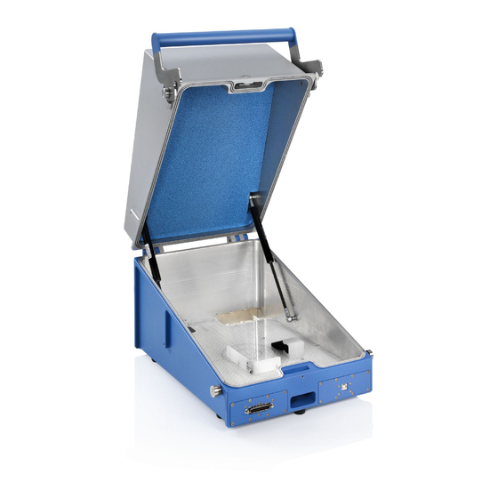
® R&S CMU-Z10/-Z11/-Z12/-Z13 Short Description ® Short Description of R&S CMU-Z10/-Z11/-Z12/-Z13 ® The R&S CMU-Z10/-Z11/-Z12/-Z13 test equipment is a complete solution for simple coupling and interference-free testing of mobile phones (MS) in the complete frequency range between 770 MHz and 2.2 GHz. -
Page 8: Rear Connectors
® Short Description R&S CMU-Z10/-Z11/-Z12/-Z13 Rear Connectors ® On its rear side the antenna coupler R&S CMU-Z10 is equipped with two N connectors for input and output of RF test signals, a sub-D connector for input and output of DC, AF or data signals, and an ®... -
Page 9: Coupling Factors
® R&S CMU-Z10/-Z11/-Z12/-Z13 Short Description The USB feed through must be connected to the test instrument and the MS under test using two appropriate, shielded USB cables according to standard USB 1.1. At present USB 2.0 is not supported. Note: Connecting USB cables and shielding The USB feed through causes no radiation that might impair the shielding effect of the chamber. -
Page 10: Input Coupling Factor (-> Ext. Att. Input)
Coupling Factors CMU-Z10/-Z11/-Z12 Input Coupling Factor (–> Ext. Att. Input) If an external input attenuation is reported to the instrument, all levels measured are referred to the output of the DUT and therefore shifted with respect to the actual level at the input connectors of the CMU. - Page 11 ® R&S CMU-Z10/-Z11/-Z12/-Z13 Coupling Factors 4. Access the GSMxxx-MS function group (where xxx corresponds to the GSM band of your MS), ® Signalling test mode, to establish a call between the R&S CMU 200 and the MS, setting the MS to a definite Power Control Level (PCL).
-
Page 12: Installation Instructions
Installation Instructions CMU-Z10/-Z11/-Z12 Fig. 4 GSM900 Signalling: AF/RF Installation Instructions ® ® It is recommended to use the antenna coupler R&S CMU-Z10 together with the shielding cover R&S CMU-Z11. The shielding cover may even be required in some places to comply with local EMC regulations;... - Page 13 ® R&S CMU-Z10/-Z11/-Z12/-Z13 Installation Instructions 4. Fix the round bushes for the closing mechanism of the cover on both sides of the antenna coupler using the large (M4x14) Phillips screws (only if they are not fixed ex factory). Transport lock for R&S CMU-Z11 Slot for closing the cover during operation,...
-
Page 14: Mounting The Bluetooth Antenna
Performance Test CMU-Z10/-Z11/-Z12 Mounting the Bluetooth Antenna ® ® To upgrade an antenna coupler R&S CMU-Z10 with a Bluetooth antenna R&S CMU-Z12 proceed as follows (see Fig. 5 above): 1. Unscrew the three Phillips screws at the rear of the coupler to remove the metal plate covering the opening for the antenna connector (see Fig. -
Page 15: Maintenance
® R&S CMU-Z10/-Z11/-Z12/-Z13 Maintenance Maintenance ® The electrical components of the antenna coupler R&S CMU-Z10 and the Bluetooth antenna do not require any particular maintenance. The mechanical expendable parts are shown in Fig. 6 below. Replacing the RF Sealing Cord ®... - Page 16 Maintenance CMU-Z10/-Z11/-Z12 HANDLE (1050.1120.00) LEVER (1050.1137.00) Fig. 6 Mechanical expendable parts with order numbers 1158.9537.12...
Need help?
Do you have a question about the R&S CMU-Z10 and is the answer not in the manual?
Questions and answers