Table of Contents
Advertisement
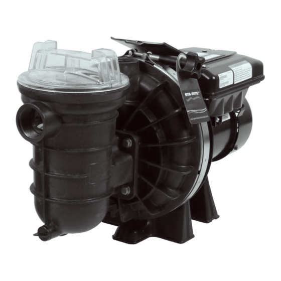
STA-RITE
VS
®
VARIABLE SPEED PUMPS
S5P1R-VS & S5P2R-VS
INSTALLATION GUIDE / INSTALLATIEHANDLEIDING
BEDIENUNGSANLEITUNG / GUIDE DE L'INSTALLATION
GUIA DE INSTALACION / GUIDE ALL'INSTALLAZIONE
IMPORTANT SAFETY INSTRUCTIONS READ AND FOLLOW ALL INSTRUCTIONS SAVE THESE INSTRUCTIONS
WATER SOLUTIONS P-INSB-STVS (Rev. 09/2016)
Advertisement
Table of Contents


Need help?
Do you have a question about the S5P1R-VS and is the answer not in the manual?
Questions and answers