Festo CMMS-ST-C8-7-G2 Mounting And Installation
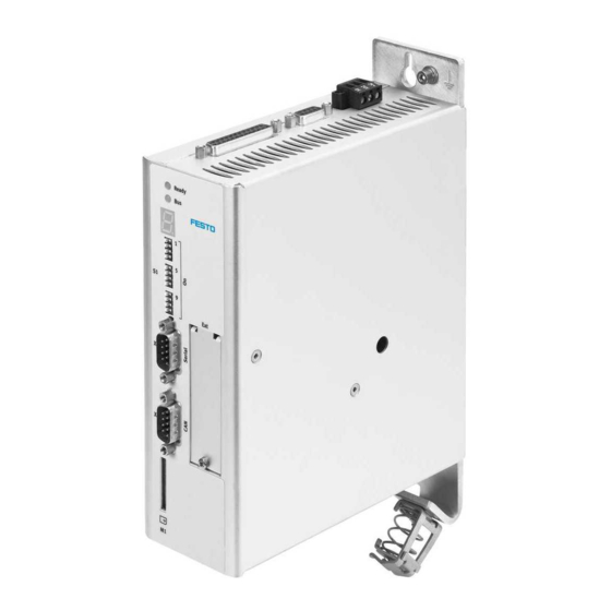
Motor controller
Hide thumbs
Also See for CMMS-ST-C8-7-G2:
- Manual (86 pages) ,
- Original instructions (4 pages) ,
- Description (246 pages)

Related Manuals for Festo CMMS-ST-C8-7-G2


Summary of Contents for Festo CMMS-ST-C8-7-G2
- Page 1 Motor controller CMMS-ST-C8-7-G2 Description Mounting and installation 8040101 1404NH [8034456]...
- Page 2 Essential or useful accessories. Information on environmentally sound usage. Text designations: • Activities that may be carried out in any order. 1. Activities that should be carried out in the order stated. – General lists. Festo – GDCP-CMMS-ST-G2-HW-EN – 1404NH –...
-
Page 3: Table Of Contents
............The entire system for the CMMS-ST-C8-7-G2 . - Page 4 ............Festo – GDCP-CMMS-ST-G2-HW-EN – 1404NH – English...
- Page 5 CMMS-ST-C8-7-G2 Notes on this documentation This documentation is intended to help you safely work with the motor controller CMMS-ST-C8-7-G2 and describes the functions, commissioning and error messages. Target group This documentation is intended exclusively for technicians trained in control and automation techno- logy, who have experience in installation, commissioning, programming and diagnostics of positioning systems.
- Page 6 Tab. 4 Manufacturing month Type codes CMMS – – – – Interfaces CMMS Motor controller, standard Motor technology Stepper motor Nominal current Input voltage 48 V DC Generation 2nd generation Fig. 1 Type codes Festo – GDCP-CMMS-ST-G2-HW-EN – 1404NH – English...
- Page 7 – Control and parameterisation via device profile CiA 402 (DS 402). Software help Help on the CMMS-AS plug-in CMMS-AS – Surface and functions in the Festo Help on the CMMD-AS plug-in CMMD-AS Configuration Tool for the plug-in Help for the CMMS-ST plug-in CMMS-ST Tab.
-
Page 8: Safety And Requirements For Product Use
• Perform a risk assessment in accordance with the EC machinery directive. • Based on this risk assessment, design the safety system for the entire machine, taking into account all integrated components. This also includes the electric drives. Bypassing of safety equipment is impermissible. Festo – GDCP-CMMS-ST-G2-HW-EN – 1404NH – English... -
Page 9: Intended Use
1.1.2 Intended use The motor controller CMMS-ST-C8-7-G2. is intended for use as a controller for two-phase step motors of the EMMS-ST and MTR-ST series. It enables closed loop control of torque (current), speed and posi- tion, as well as positioning control with stored positioning records. The motor controller is designed for installation in a control cabinet. -
Page 10: Requirements For Product Use
The motor controller carries the CE marking; for standards and test values Appendix A.1. The product-relevant EU directives can be found in the declaration of conformity. For certificates and the declaration of conformity for this product please refer to www.festo.com/sp. Festo – GDCP-CMMS-ST-G2-HW-EN – 1404NH – English... -
Page 11: Product Overview
Product overview Product overview The entire system for the CMMS-ST-C8-7-G2 Power switch Fuse – dependent on 3 and 4 24 V power supply unit for control voltage Power supply unit for power supply Motor controller CMMS-ST-C8-7-G2 PC with serial connecting cable for para-... -
Page 12: Scope Of Delivery
Motor controller CMMS-ST-C8-7-G2 Operator package – Brief description – CD-ROM with following contents: – Parameterisation software “Festo Configuration Tool” (FCT) – Documentation on the product – S7 module – Configuration files for the supported bus systems (e.g. device core data for PROFIBUS (GSD), electronic data sheet (EDS) for DeviceNet, etc.) -
Page 13: Device View
[EXT]: Slot for optional control interfaces (PROFIBUS DP, DeviceNet) [M1]: card slot for SD memory card [X4]: CAN bus [X5]: RS232/RS485 Earthing screw (central FU connection) Fig. 2.2 Front view CMMS-ST-C8-7-G2 front Festo – GDCP-CMMS-ST-G2-HW-EN – 1404NH – English... - Page 14 Product overview [X9] Power supply [X10] Master/slave (bi-directional interface) [X1] I/O interface Fig. 2.3 Top CMMS-ST-C8-7-G2 view [X3] STO interface [X2] Encoder [X6] Motor Shield connection terminal Fig. 2.4 Bottom CMMS-ST-C8-7-G2 view Festo – GDCP-CMMS-ST-G2-HW-EN – 1404NH – English...
-
Page 15: Display And Control Elements
Number: Two-position main index (x x), single-position subindex (y). Example: - 1 7 0 - Appendix B. 1) Several characters are displayed one after the other. Fig. 2.2 2 ) Tab. 2.2 Seven-segment operation and error display ( Festo – GDCP-CMMS-ST-G2-HW-EN – 1404NH – English... -
Page 16: Led Displays
S1.1 … 7 ON/OFF (example) Significance DIP switch S1.1 is the low-order bit. Example: address = 1011011 = 91 1) Additional information Description of functions and commissioning, GDCP-CMMS/D-FW-..Tab. 2.5 CAN bus address or MAC-ID Festo – GDCP-CMMS-ST-G2-HW-EN – 1404NH – English... -
Page 17: Slot [Ext]
Description of functions and commissioning, GDCP-CMMS/D-FW-..Tab. 2.6 CAN-bus transmission rate 2.4.4 Slot [EXT] Fig. 2.2 4 ) enables the option of expanding CMMS-ST-C8-7-G2 by other interfaces, e.g.: The slot ( – CAMC-PB: interface for PROFIBUS DP – CAMC-DN: interface for DeviceNet. -
Page 18: Mechanical Installation
Installation dimensions D1 @ D2 @ D3 @ Dim. [mm] Approx. 60 Approx. 56 Approx. 161 Dim. [mm] Approx. 257 Approx. 224 Approx. 206.25 Approx. 181 12.5 10.5 Tab. 3.1 CMMS-ST-C8-7-G2: Installation dimensions Festo – GDCP-CMMS-ST-G2-HW-EN – 1404NH – English... -
Page 19: Mounting
For vertical mounting onto a control cabinet mounting plate: For the motor controller CMMS-ST-C8-7-G2 no mounting brack- ets are required. The back wall has mounting options. The back wall is part of the radiator profile and transfers heat to the mounting plate. -
Page 20: Disassembly
Danger of burns from hot surfaces Dependent on the load of the motor controller, housing temperatures > 80 °C are pos- sible in operation. • Touch them only in a switched-off, cooled-off status. Festo – GDCP-CMMS-ST-G2-HW-EN – 1404NH – English... -
Page 21: Electrical Installation
• Before installation: Earth the system parts and use appropriate ESD equipment (e.g. shoes, earthing straps etc.). • After installation: Seal unassigned D-sub plug connectors with protective caps (available at authorized dealers). • Observe the handling specifications for electrostatically sensitive devices. Festo – GDCP-CMMS-ST-G2-HW-EN – 1404NH – English... -
Page 22: Instructions For Safe And Emc-Compliant Installation
Instructions for safe and EMC-compliant installation The CMMS-ST-C8-7-G2 motor controllers have been approved in accordance with product standard EN 61800-3 that is applicable to electric drives. Components from Festo have been used for this purpose (e.g. motor/encoder cables). The declaration of conformity for the EMC directive (electromagnetic compatibility) is available at www.festo.com. -
Page 23: Emc-Compliant Wiring
1) Permitted total line length of field bus at a bit rate of 1 Mbit/s. Observe details in the documentation of your control system or bus interface. 2) With motor cables with a length of > 15 m, only use cables with a capacity lining of < 200 pF/m. Tab. 4.2 EMC-compliant wiring Festo – GDCP-CMMS-ST-G2-HW-EN – 1404NH – English... -
Page 24: Protective Earthing Of The Motor Controller
• Apply the cable screening of the motor cable to the shield connection terminal of the motor controller Chapter 4.8.2. • Apply the cable screening of the encoder cable flat on the plug housing of the con- nection [X2] Chapter 4.4. Festo – GDCP-CMMS-ST-G2-HW-EN – 1404NH – English... -
Page 25: I/O Interface [X1]
DIN 12 Pin allocation Positioning (single record) Tab. 4.5 Jog/teach Tab. 4.6 Record linking Tab. 4.7 Synchronisation Tab. 4.8 1) Standard allocation of the I/O interface Tab. 4.4 Function-dependent configuration of digital inputs Festo – GDCP-CMMS-ST-G2-HW-EN – 1404NH – English... - Page 26 DOUT2 24 V 100 mA Start acknowledged (low active) 1) Default setting, configurable in the Festo Configuration Tool (FCT). 2) Pin allocation with control via analogue input 3) Pin allocation for flying measurement Tab. 4.5 Pin allocation of the I/O interface [X1], positioning (single record)
- Page 27 24 V 100 mA Output: Controller ready for operation (high active) DOUT2 24 V 100 mA Teach confirmed 1) Default setting, configurable in the Festo Configuration Tool (FCT). Tab. 4.6 Pin allocation: I/O interface [X1], jog/teach Festo – GDCP-CMMS-ST-G2-HW-EN – 1404NH – English...
- Page 28 Output: Controller ready for operation (high active) DOUT2 24 V 100 mA Start confirmed (high active) 1) Default setting, configurable in the Festo Configuration Tool (FCT). Tab. 4.7 Pin allocation: I/O interface [X1], record linking Festo – GDCP-CMMS-ST-G2-HW-EN – 1404NH – English...
- Page 29 Output: Controller ready for operation (high active) DOUT2 24 V 100 mA Output: position synchronous (high active) 1) Default setting, configurable in the Festo Configuration Tool (FCT). Tab. 4.8 Pin allocation: I/O interface [X1], synchronisation Festo – GDCP-CMMS-ST-G2-HW-EN – 1404NH – English...
-
Page 30: Encoder [X2]
Increment generator signal B, negative polarity 5 V, Ri = 120 Ohm Increment generator zero pulse N, neg- ative polarity Internal screen for the connecting cable 1) R Internal resistance Tab. 4.10 Pin allocation: encoder [X2] Festo – GDCP-CMMS-ST-G2-HW-EN – 1404NH – English... - Page 31 Electrical installation The motor controller supports the activation of Festo two-phase hybrid step motors with an encoder mounted on the motor shaft (see www.festo.com/catalogue). The encoder is used to control cur- rent, speed and position. Commutation of the motor is also controlled with the encoder.
-
Page 32: Sto Interface [X3]
Pin 1 and Pin 2 at the X3 interface to operate the motor controller Tab. 4.12. This deactivates the integrated safety function! When using this circuitry for the CMMS-ST-C8-7-G2, safety in the application must be ensured through other appropriate measures. Festo – GDCP-CMMS-ST-G2-HW-EN – 1404NH – English... -
Page 33: Circuitry With Use Of The Sto Safety Function [X3]
• Make sure that no jumpers or the like can be used parallel to the safety wiring, e.g. through the use of the maximum wire cross sections or appropriate wire end sleeves with insulating collars. • Use twin wire end sleeves for looping through lines between neighbouring devices. Festo – GDCP-CMMS-ST-G2-HW-EN – 1404NH – English... -
Page 34: Can [X4]
To prevent transmission faults caused by signal overlap: • When communicating via the serial interface only use separate lines that are con- figured according to the specified pin allocation for RS485 or RS232. Festo – GDCP-CMMS-ST-G2-HW-EN – 1404NH – English... - Page 35 Positive transmission and reception signal Reference potential 0 V DC, not galvanically isolated – – – – – – – – – RS485_B – Negative transmission and reception signal Tab. 4.17 Pin allocation RS485 [X5] Festo – GDCP-CMMS-ST-G2-HW-EN – 1404NH – English...
-
Page 36: Motor [X6]
2) Recommendation: When using cables made by other manufacturers, only use motor cables on which the cables for the temperat- ure sensor (T–, T+) and the cable for the holding brake (BR–, BR+) are in twisted pairs and screened. Tab. 4.19 Pin allocation: Motor [X6] Festo – GDCP-CMMS-ST-G2-HW-EN – 1404NH – English... -
Page 37: Connecting The Screening Of The Motor Cable
• Make sure the nominal voltage tolerances are maintained at the terminals of the holding brake ( Tab. A.8, logic supply). • Observe the maximum output current provided by the motor controller ( Tab. A.8). Festo – GDCP-CMMS-ST-G2-HW-EN – 1404NH – English... -
Page 38: Power Supply [X9]
Intermediate circuit voltage (power) 24 V DC ± 20% Power supply to control unit (logic) 24 V Common reference potential for the 0 V intermediate circuit and the control section Tab. 4.21 Pin allocation: voltage supply [X9] Festo – GDCP-CMMS-ST-G2-HW-EN – 1404NH – English... -
Page 39: Connection To The Supply Voltage
– Ensure that the intermediate circuit voltage does not continue to rise beyond the level stipulated for logic power supply in the technical data. Festo – GDCP-CMMS-ST-G2-HW-EN – 1404NH – English... -
Page 40: Master/Slave Interface [X10]
– Negative polarity in accordance with Ri = 120 Ω RS422 max. 150 kHz – Screening for the connecting cable 1) Pin 4 and pin 9 are connected internally Tab. 4.23 Pin allocation: Master/slave interface [X10] Festo – GDCP-CMMS-ST-G2-HW-EN – 1404NH – English... -
Page 41: Commissioning
Danger from unexpected movement of the motor or axis • Make sure that the movement does not endanger anyone. • Parameterise the motor controller with the Festo Configuration Tool (FCT) before enabling the controller via DIN5 [X1.9]. – Bypassing of safety equipment is impermissible. -
Page 42: Maintenance, Updating, Repair And Replacement
Observe the disassembly instructions in section . 3.3. 6.3.1 Disassembly and installation Information on removing and installing can be found here: – Mounting Section 3.2 – Disassembly Section 3.3. – Commissioning Section 5. Festo – GDCP-CMMS-ST-G2-HW-EN – 1404NH – English... -
Page 43: Disposal
Maintenance, updating, repair and replacement 6.3.2 Disposal Observe the local regulations for environmentally appropriate disposal of electronic modules. The product is RoHS-compliant. Festo – GDCP-CMMS-ST-G2-HW-EN – 1404NH – English... -
Page 44: A Technical Appendix
1) The device is intended for use in an industrial environment. Outside of industrial environments, e.g. in commercial and mixed-res- idential areas, actions to suppress interference may have to be taken. Tab. A.1 Technical data, general Festo – GDCP-CMMS-ST-G2-HW-EN – 1404NH – English... - Page 45 Switch-off temperature, heat sink [°C] Power section Vibration and shock resistance Operation in accordance with EN 61800-5-1, section 5.2.6.4 Transport in accordance with EN 61800-2, section 4.3.3 Tab. A.2 Technical data: Operating and ambient conditions Festo – GDCP-CMMS-ST-G2-HW-EN – 1404NH – English...
-
Page 46: Connection Data
[V DC] Output reaction time [ms] Protective function Against polarity reversal, feedback, automatic shutdown of the output in the event of an over- load; automatic restart when the short circuit has been remedied Festo – GDCP-CMMS-ST-G2-HW-EN – 1404NH – English... -
Page 47: Encoder [X2]
Number of lines 1000, 500, 400, 200 Critical frequency [kHz] > 100 Encoder supply (from the controller) Voltage [V DC] 5 (-5 % … +5 %) Current [mA] Tab. A.4 Connection data: Encoder [X2] (input) Festo – GDCP-CMMS-ST-G2-HW-EN – 1404NH – English... -
Page 48: Sto Interface [X3]
Transmission rate [bps] 9600…115200 Factory setting Transmission rate [bps] 9600 Data bits Parity none Stop bit ESD protection Driver protected against electrostatic discharge up to 16 kV Tab. A.6 Connection data: RS232/RS485 [X5] Festo – GDCP-CMMS-ST-G2-HW-EN – 1404NH – English... -
Page 49: Motor [X6]
10 (typical) Capacitive [nF] Switching delay [ms] Motor temperature monitoring Digital sensor (N/C contact) Cold Analogue sensor (Silicon temperature sensor, e.g. KTY81 ... 84) 1 or 2 Tab. A.7 Connection data: Motor connection [X6] Festo – GDCP-CMMS-ST-G2-HW-EN – 1404NH – English... -
Page 50: Power Supply [X9]
24 ± 20% Max. ripple in input voltage 1.0 at 100 Hz Nominal current – Outputs load-free – Without current for holding brake Max. current (incl. holding brake) Tab. A.8 Connection data: Power supply [X9] Festo – GDCP-CMMS-ST-G2-HW-EN – 1404NH – English... -
Page 51: Master/Slave Interface [X10]
According to RS422 standard Input signals A/B, CW/CCW, CLK/DIR Output signals A/B/N Angle resolution/number of lines 1 … 2048 Output impedance [Ω] Critical frequency [kHz] > 150 Tab. A.10 Connection data: Master/slave interface [X10] Festo – GDCP-CMMS-ST-G2-HW-EN – 1404NH – English... -
Page 52: B Diagnostic Messages
Under section B.3, you will find the error codes in accordance with CiA301/402 and the error bit num- bers with allocation to the error numbers of the diagnostic messages. Under section B.4, you will find the PROFIBUS diagnostic bits with allocation to the error numbers of the diagnostic messages. Festo – GDCP-CMMS-ST-G2-HW-EN – 1404NH – English... -
Page 53: Diagnostic Messages With Instructions For Fault Clearance
Cause Motor overloaded, temperature too high. – Motor too hot. – Sensor defective? Action • Check parameters (current regulator, current limits). If the error persists when the sensor is bypassed: Device defective. Festo – GDCP-CMMS-ST-G2-HW-EN – 1404NH – English... - Page 54 Action • Separate device from the entire peripheral equipment and check whether the error is still present after reset. If so, an internal defect is present Repair by the manufacturer. Festo – GDCP-CMMS-ST-G2-HW-EN – 1404NH – English...
- Page 55 – external stop signal (termination of a homing phase). Action • Check homing sequence. • Check arrangement of the switches. • If applicable, lock the STOP input during homing if it is not desired. Festo – GDCP-CMMS-ST-G2-HW-EN – 1404NH – English...
- Page 56 Over a period of 2 SYNC intervals, the SYNC telegram or the PDO of the controller has failed. Action • Re-start CAN controller. • Check CAN configuration in the controller (SYNC telegram must be parameterised). • Check wiring. Festo – GDCP-CMMS-ST-G2-HW-EN – 1404NH – English...
- Page 57 Output stage temperature 5 °C below maximum configurable Cause The output stage temperature is greater than 90 °C. Action • Check installation conditions, cooling through the housing surface, integrated heat sink and back wall. Festo – GDCP-CMMS-ST-G2-HW-EN – 1404NH – English...
- Page 58 Data flash Code Message Reaction 26-1 5581h Checksum error PS off Cause Checksum error of a parameter set. Action • Load factory setting. • If the error is still present, the hardware is defective. Festo – GDCP-CMMS-ST-G2-HW-EN – 1404NH – English...
- Page 59 Error group 32 Intermediate circuit Code Message Reaction 32-8 3285h Power supply failure during controller enable PS off Cause Interruption/power failure while the controller enable was active. Action • Check mains voltage/power supply. Festo – GDCP-CMMS-ST-G2-HW-EN – 1404NH – English...
- Page 60 Unknown command found during record continuation. Action • Check parameterisation. 41-9 6192h Error in path program jump destination configurable Cause Jump to a positioning record outside the permitted range. Action • Check parameterisation. Festo – GDCP-CMMS-ST-G2-HW-EN – 1404NH – English...
- Page 61 Positive hardware limit switch reached. Action • Check parameterisation, wiring and limit switches. 43-9 8612h Error in limit switch configurable Cause Both hardware limit switches are active simultaneously. Action • Check parameterisation, wiring and limit switches. Festo – GDCP-CMMS-ST-G2-HW-EN – 1404NH – English...
- Page 62 24 V DC. 64-2 DeviceNet communication error 7582h PS off Cause – Receive buffer overflow. – Too many messages received within a short period. Action • Reduce the scan rate. Festo – GDCP-CMMS-ST-G2-HW-EN – 1404NH – English...
- Page 63 • Check that the network is connected correctly and does not malfunction. 65-1 7582h DeviceNet communication error configurable Cause I/O connection timeout. No I/O message received within the expected time. Action • Please contact Technical Support. Festo – GDCP-CMMS-ST-G2-HW-EN – 1404NH – English...
- Page 64 Not every change is permissible. Error group 79 RS232 error Code Message Reaction 79-0 RS232 communication error 7510h configurable Cause Overflow when receiving RS232 commands. Action • Check wiring. • Check the transmitted data. Festo – GDCP-CMMS-ST-G2-HW-EN – 1404NH – English...
-
Page 65: Error Codes Via Cia 301/402
6380h 70-3 Operating mode error configurable 7380h 08-0 Error in encoder supply PS off 7500h 22-0 Error in PROFIBUS initialization PS off 22-2 PROFIBUS communication error configurable 7510h 79-0 RS232 communication error configurable Festo – GDCP-CMMS-ST-G2-HW-EN – 1404NH – English... - Page 66 43-0 Negative limit switch error configurable 43-1 Positive limit switch error configurable 43-9 Error in limit switch configurable 8681h 42-1 Positioning: Error in pre-computation configurable 8A81h 11-1 Homing error PS off Festo – GDCP-CMMS-ST-G2-HW-EN – 1404NH – English...
-
Page 67: B.4 Profibus Diagnostics
Time out with fast stop PS off E111 “Error during homing” 11-1 Homing error PS off E149 “Motor identification” 14-9 Error, motor identification PS off E190 “I2t at 80 %” 19-0 I²t at 80 % configurable Festo – GDCP-CMMS-ST-G2-HW-EN – 1404NH – English... - Page 68 PS off stage” cuit E03x “Overheating error 03-1 Temperature monitoring, motor configurable (motor)” E040 “Overtemperature 04-0 Excess/low temperature of power configurable power stage” electronics E080 “Encoder supply” 08-0 Error in encoder supply PS off Festo – GDCP-CMMS-ST-G2-HW-EN – 1404NH – English...
- Page 69 ....... . Installation clearance ....Festo – GDCP-CMMS-ST-G2-HW-EN – 1404NH – English...
- Page 70 Copyright: Festo AG & Co. KG Postfach 73726 Esslingen Germany Phone: +49 711 347-0 Fax: +49 711 347-2144 e-mail: service_international@festo.com Reproduction, distribution or sale of this document or communica- tion of its contents to others without express authorization is Internet: prohibited.
Need help?
Do you have a question about the CMMS-ST-C8-7-G2 and is the answer not in the manual?
Questions and answers