Table of Contents
Advertisement
Quick Links
Advertisement
Table of Contents

Related Manuals for Kusam-meco 405


Summary of Contents for Kusam-meco 405
- Page 1 DIGITAL MULTIMETER...
-
Page 2: Table Of Contents
Table of Contents TAKE MEASUREMENT CAREFULLY AND YOU’LL SPARE YOUR METER AND YOURSELF, SOME PAIN Title Page Nearly every electrical engineer has a hand held Overview digital multimeter (DMM). We sometimes take them Unpacking Inspection for granted, until we damage them or “burn them out” Features if you incorrectly connect your DMM to a circuit, or if General Specification... -
Page 3: Unpacking Inspection
Description Qty. Operation”carefully before using the Meter. English Operating Manual 1 piece Digital Multimeter Model - 405 (hereafter referred to as “the Meter”) is a 4½ digits TRMS Multimeter with Test Lead 1 pair steady operations, and highly reliable hand-held... -
Page 4: Features
FEATURES : GENERAL SPECIFICATIONS : Low power consumption CMOS double : 4½ digit LCD. Disp Maximum reading 19999 integration, A/D transform integrated circuit, with Function and unit sign Auto Zero Calibration, Auto Polarity display, annunciators. Data Hold, Low Battery & Over range Digit Size : 17mm(H) indication. -
Page 5: Electrical Specification
ELECTRICAL SPECIFICATION : AC CURRENT (TRUE RMS) Range Resolution Accuracy DC VOLTAGE Range Resolution Accuracy ±(0.8% rdg + 10 dgts) 200 mA ±(0.05% rdg + 3dgts) ±(2.5% rdg + 10 dgts) Burden Voltage : 300mV for 200 A, 2mA, 20mA 1000 600mV for 200mA &... -
Page 6: Frequency
FREQUENCY Rules For Safe Operation (1) Range Accuracy Input Imped. Resolution Warning ±(0.5% rdg+3dgts) 10M // 10pF To avoid possible electric shock or personal 20 KHz 200KHz injury, and to avoid possible damage to the Meter or to the equipment under test, adhere to Sensitivity : 50mV rms (Sine Wave), 400mV rms at >... -
Page 7: International Electrical Symbols
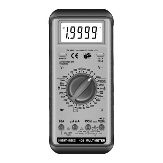
CAT. II International Electrical Symbols 200mA MAX 1000V FUSED 20A MAX 750V FUSED 405 MULTIMETER AC (Alternating Current). DC (Direct Current). ( Figure 1) Both DC & AC. 1) LCD DISPLAY : A 4½ digit display (maximum reading 19999) Grounding. -
Page 8: Functional Buttons
Functional Buttons Display Symbols (see figure 2) Below table indicates the functional button operations Operation Performed Buttons 1.9.9.9.9 Switch the Meter on and off. POWER Press the POWER button to (Black Button) switch on the Meter. Press the POWER button to turn off the Meter. -
Page 9: Measurement Operation
FUSED 20A MAX 750V FUSED select a higher range in order to obtain a correct 405 MULTIMETER reading. In each range, the Meter has an input impedance ( Figure 3 ) of approx. 10M . This loading effect can cause measurement errors in high impedance circuits. -
Page 10: Ac Voltage Measurement
CAT. II Black 200mA MAX 1000V FUSED 20A MAX 750V FUSED 405 MULTIMETER C) AC Current Measurement (see figure 5) ( figure 4) LOGIC Warning : 1.9999 To avoid harm to you or damages to the Meter from electric shock, please do not attempt to... -
Page 11: Dc Current Measurement
High - Voltage capacitors. 200mA MAX 1000V FUSED 20A MAX 750V FUSED 405 MULTIMETER Insert the red test lead into the mA or 20A terminal and the black test lead into the COM terminal. (figure 6) rotary switch to an appropriate Warning : measurement position in Current range. -
Page 12: Measuring Resistance
20A MAX FUSED 750V FUSED The measured value is shown on the display. 405 MULTIMETER (figure 7) Caution The resistance range has 6 measurement positions If the value of current to be measured is on the rotary switch : 200... - Page 13 200mA MAX 1000V FUSED 20A MAX 750V FUSED 405 MULTIMETER Using Resistance measurement function in a Live circuit will produce false results and may damage the instrument. In many cases (figure 8) the suspect component must be disconnected The frequency measurement range is 2kHz, 20kHz, from the circuit to obtain an accurate reading.
-
Page 14: Duty Cycle Measurement
750V FUSED 3) Connect the BLACK probe tip to the Common 405 MULTIMETER Bus of the logic circuitry to be measured. 4) Connect the RED probe tip to the point to be Insert the red test lead into the V terminal and the black test lead into the COM terminal. -
Page 15: Maintenance
Maintenance Caution : In a circuit, a good diode will produce a Warning forward voltage drop reading of 0.5V to 0.8V; To avoid false reading, replace the battery as soon However ; the reverse voltage drop reading can as the battery indicator appears. -
Page 16: Test Certificate
The instrument has been calibrated by using equipment which has already been calibrated to standards traceable to national standards. MODEL NO. ___________ SERIAL NO. ___________ DATE: ___________ ISO 9001 KUSAM-MECO REGISTERED PASS... -
Page 17: Warranty
WARRANTY THIS WARRANTY IS BUYER’S SOLE AND EXCLUSIVE REMEDY AND IS IN LIEU OF ALL Each “KUSAM-MECO” product is warranted to be OTHER WARRANTIES, EXPRESS OR IMPLIED, free from defects in material and workmanship INCLUDING BUT NOT LIMITED TO ANY IMPLIED under normal use &...
Need help?
Do you have a question about the 405 and is the answer not in the manual?
Questions and answers