Table of Contents
Advertisement
Quick Links
Advertisement
Table of Contents

Subscribe to Our Youtube Channel
Related Manuals for Kusam-meco M3500A


Summary of Contents for Kusam-meco M3500A
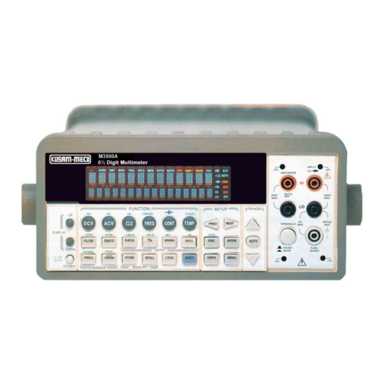
- Page 1 An ISO 9001:2000 Company 6 ½ Digit Multimeter M3500A Operation Manual...
- Page 2 Operation Manual M3500A DMM...
-
Page 3: Table Of Contents
EATURE VERVIEW ..................... 6 1.2 W ARRANTY NFORMATION ................... 7 1.3 P RECAUTION OF PERATION ..................8 1.4 U M3500A ....................9 PKEEP OF 1.5 S AFETY NFORMATION ....................9 1.6 S YMBOLS AND ERMS ....................10 1.7 I NSPECTION ........................ - Page 4 3.7.2.1 2-Wire RTD Measurements..............43 3.7.2.2 3-Wire RTD Measurements..............44 3.7.2.3 4-Wire RTD Measurements..............46 4 FRONT PANEL OPERATIONS..................49 4.1 M EASUREMENT ONFIGURATION ................49 4.1.1 Set ADC (Auto Zero & Auto Gain) ........... 49 4.1.2 Filter ......................52 4.1.2.1 AC Filter ......................
- Page 5 4.4.7 Initial Mode....................98 4.4.8 Language....................99 4.4.9 Error Condition..................100 4.4.10 Firmware Revision................101 4.4.11 Calibration .................... 102 5 REMOTE INTERFACE OPERATIONS................103 5.1 P USB C UTPUT ONNECTOR ............103 5.2 S ETTING EMOTE NTERFACE ..............104 5.3 R EMOTE NTERFACE OMMANDS...
- Page 12 Part Name Part Number Multi-point Scanner Card M3500-opt01 Thermocouple adapter M3500-opt02 Adapters (Banana to BNC Adapter) M3500-opt03 GPIB Card M3500-opt04 RTD Probe Adapter M3500-opt05 Table 1-1...
-
Page 13: Overview
2.1 Setting up Your M3500A Digital Multimeter The purpose of this section is to prepare users for using M3500A DMM. You may want to check if you have all the parts with your multimeter. All our products are handled and inspected professionally before shipping out to our customers. - Page 14 Figure 1-1 【Step 2】(Pull out the handle) When the handle is turned up to 90° with the multimeter, pull out the handle from the multimeter as shown in Figure 1-2. Figure 1-2 Ⅱ. Adjusting the position for your convenience Here are some example positions to suit users’ needs. 【Position 1】...
- Page 15 Figure 1-3 【Position 2】 The adjusted position is for operation as shown in Figure 1-4。 Figure 1-4 【Position 3】 The carrying position is with the handle as shown in Figure 1-5。 Figure 1-5...
-
Page 16: To Connect The Power
AC power. An incorrect voltage setting may cause severe damage to your instrument. Warning! The power cord supplied with M3500A contains a separate ground wire for use with grounded outlets. When proper connections are made, instrument chassis is connected to power line ground through the ground wire in the power cord. - Page 17 Figure 2-1 【Step 2】 Open the voltage setting selector cap as shown in Figure 2-2. (You might need a screwdriver to do so.) Figure 2-2 【Step 3】 Remove the red voltage setting selector from the right middle seam as shown in Figure 2-3. (You might need a screwdriver to do so.)
- Page 18 Figure 2-3 【Step 4】 Turn it over to 220V position as shown in Figure 2-4. Figure 2-4 【Step 5】 Insert the voltage setting selector back into the socket and close the cap as shown in Figure 2-5. Figure 2-5...
-
Page 19: To Change The Fuse
2.1.2.2 To change the fuse Warning! Before replacing the power-line fuse, make sure the multimeter is disconnected from the AC power. You must be a qualified personnel to perform this action. Warning! For continued protection against fire or instrument damage, only replace fuse with the same type and rating. If the instrument repeatedly blows fuses, locate and correct the cause of the trouble before replacing the fuse. - Page 20 【Step 2】 Open the voltage setting selector cap as shown in Figure 2-7. (You might need a screwdriver to do so.) Figure 2-7 【Step 3】 Remove the red voltage setting selector from the right middle seam as shown in Figure 2-8. (You might need a screwdriver to do so.) Figure 2-8...
- Page 21 【Step 4】 Remove the broken fuse from the selector as shown in Figure 2-9. Figure 2-9 【Step 5】 Replace with the new fuse as shown in Figure 2-10. Figure 2-10 【Step 6】 Insert the voltage setting selector back into the socket and close the cap as shown in Figure 2-11.
- Page 22 【Step 7】 Make sure the power switch on the front panel is in “Power OFF” condition before plugging as shown in Figure 2-12. Figure 2-12 Power switch: “POWER OFF” 【Step 8】 After finishing the above procedures, you can plug in your power cord as shown in Figure 2-13.
-
Page 23: Factory Default When Power-On
【Step 9】 Press on the power switch on the front panel for activating M3500A as shown in Figure 2-14. Figure 2-14 Power switch: - “POWER ON” 2.1.3 Factory Default When Power-ON Table 2-1 shows the factory default of M3500A. Function... - Page 24 AC Digits Slow 5.5 Voltage DC digits (1 PLC) Range Auto AC Digits Slow 5.5 Current DC Digits (1 PLC) Range Auto Digits Frequency Range AUTO and Period Medium Rate (100ms) Digits Diode Test Range Rate 0.1 PLC Slow 5.5 Resistance Digits (1 PLC)
-
Page 25: Features
Easy & Free PC applications. 2.3 M3500A Function Introduction For users to become familiar with the M3500A DMM, we will give a brief introduction to the basic operations of M3500A DMM. There are three major parts of M3500A: (2.3.1) the front panel, (2.3.2) the display, and (2.3.3) the rear panel. - Page 27 2-3. Second row without SHIFT button: FILTER: Enable or disable the digital filter. DIGITS: Changes resolution. RATIO: Enables the dcv:dcv ratio function. %: Calculates the ratio to a target value in percentage. MIN/MAX: Captures the minimum or maximum readings from the measurement.
- Page 28 3-1. The first row in SETUP section ◁▷: Scrolls through buffer, conceals or reveals the digits while measuring. 3-2. The second row in SETUP section: ESC: Cancels selection, moving back to measurement display. ENTER: Accepts selection, moving to next choice or back to measurement display.
-
Page 29: The Display
2.3.2 The Display M3500A has a 5x7 dot matrix, dual-display with three-color (White, Red and Yellow) annunciators for a better view. There are two rows in the dual-display screen. The upper row displays readings and units. A maximum 13 characters are allowed for upper row dot-matrix display. -
Page 30: Annunciators At Right Side
OFF: Indicates the front panel display is turned off. Figure 2-18 2.3.3 The Rear Panel The rear panel of the M3500A is shown in Figure 2-19. This figure includes important abbreviated information that should be reviewed before using the instrument. - Page 31 LO & I: Used for making DC and AC current measurements. Rear Fuse: Secures your Meter against damage of strong current pulse. 2. BNC Connections: VM COMP: Voltmeter Complete Output Terminal. Outputs a low-true pulse after the completion of each measurement. EXT TRIG: External Trigger Input Terminal.
-
Page 32: Basic Measurement Function
Basic Measurement Function This chapter introduces some basic measurement functions in M3500A. You will learn how to use your M3500A multimeter to measure voltage, current, resistance, frequency, period, continuity, diode temperature in this chapter. 3.1 Voltage Measurements (DC & AC) The ranges for DC voltage measurements in M3500A are 100mV, 1V, 10V, 100V and 1000V. -
Page 36: Resistance Measurements
3.3 Resistance Measurements (2 & 4-wire) The ranges for resistance measurement are 100 Ω, 1KΩ, 10kΩ, 100kΩ, 1MΩ, 10MΩ, and 100MΩ, with a sensitivity of 100 μΩ (on 100 Ω range.) There are two modes for measuring the resistance: 2-wire mode as shown in Figure 3-6 and 4-wire mode as shown in Figure 3-7. -
Page 41: Temperature Measurements
(Refer to 4.1.8 for how to make the sensor configuration). In general, RTDs have a better accuracy and long-term stability than thermocouples. The default RTD type in M3500A is PT100 and the thermocouple is type K. Sensor Type... -
Page 46: 4-Wire Rtd Measurements
Figure 3-16 3.7.2.3 4-Wire RTD Measurements How to measure temperature with 4-Wire RTD The following Figure 3-17 shows theory diagram of 4-Wire RTD measurement. Use terminals switch to select front terminals. ① Insert a specified adapter into the front terminals. Connect the low ②... - Page 48 Figure 3-18...
-
Page 49: Front Panel Operations
The purpose of Auto Zero and Auto Gain functions are used for minimizing the offset influence on your measurements. When Auto Zero or Auto Gain is enabled, M3500A takes the input signal reading as a base value and then internally disconnects the input signal, and takes a offset reading (a null offset). - Page 50 Defaults The default settings for Auto Zero and Auto Gain are enabled. The user selected values for Auto Zero and Auto Gain are stored in a volatile memory and the default settings will be restored when the meter is power-off. How to set Auto Zero and Auto Gain You can change the Auto Zero and Auto Gain setting through the front panel or through the remote interface operation.
- Page 51 Fast 5 ½ digits Slow 5 ½ digits Fast 6 ½ digits Slow 6 ½ digits Table 4-1 ※ Note: To change resolution, refer to Section 4.1.3: Resolution Setting in this chapter. Figure 4-1 Remote Interface Operation To set Auto Zero and Auto Gain through the remote interface, use the following commands: SENSe:ZERO:AUTO {OFF|ONCE|ON} SENSe:GAIN:AUTO {OFF|ONCE|ON}...
-
Page 52: Filter
4.1.2 Filter Filter is used to remove noises in measurement readings. M3500A is equipped with two types of filters: AC filter and digital filter. AC filter is for AC measurements only. It also affects the speed of the multimeter to yield a measurement reading. -
Page 53: Digital Filter
DETector:BANDwidth {3|20|200|MIN|MAX} 4.1.2.2 Digital Filter Definition: M3500A uses an averaging digital filter to yield a reading for display from a specified number of measurement readings in the past. The past measurement readings are stored in a stack of memory. The number may be in the range of 2 to 100. - Page 54 the stack. In the repeating average mode, the multimeter waits for the measurement reading stack to fill up and then take an average to produce a reading for display. It then flushes the stack and starts over with an empty stack. Consequently, the repeating digital filter yields one reading for display every specified number of measurement readings.
-
Page 55: Resolution Setting (Digits)
SENSe:AVERage:COUNt {<value>|MINimum|MAXimum} SENSe:AVERage:COUNt? [MINimum|MAXimum] SENSe:AVERage:STATe {OFF|ON} SENSe:AVERage:STATe? 4.1.3 Resolution Setting (Digits) Definition Resolution is the number of digits a multimeter can measure. User can select the resolution for a specific measurement. The choices for the resolution setting are: fast 4.5, slow 4.5, fast 5.5, slow 5.5, fast 6.5 and slow 6.5. - Page 56 Front Panel Operation There are two ways to set the resolution. The locations of the buttons are shown with red rectangle frames in Figure 4-3. First select your desired measurement function by pressing one of the function buttons located on the first row of your meter's front panel. Press DIGITS button to select your desired resolution for your measurement.
-
Page 57: Dc Input Resistance
Definition To reduce the effect of loading errors due to the input resistance, M3500A allows user to select a much larger input resistance (> 10G Ω) for low input DC voltage (100mV, 1V and 10V) measurements. This feature is only available for DC voltage measurements and it is not applicable to other measurement functions. -
Page 58: Threshold Resistance (Continuity)
Figure 4-4 Remote Interface Operation The automatic input resistance mode can be enabled / disabled. With AUTO OFF (default), the input resistance is fixed at 10MΩ for all ranges. With AUTO ON, the input resistance is set to >10GΩ for the three lowest DC voltage ranges (100mV, 1V and 10V). -
Page 59: Range (Manual And Auto)
Press CONFIG button and then CONT button. Use ◁ and ▷ buttons to move through the digits and lower or increase the number to your desired value using △ and ▽ buttons , then press ENTER button to set the value. The locations of these buttons are shown with red rectangle frames in Figure 4-5. -
Page 60: Rate (Integration Time)
How to set the auto / manual range: You can set the auto / manual range either through the front panel operation or through the remote interface operation. Front Panel Operation First choose a measurement function on the front panel, then press “AUTO”... - Page 61 PLC (power line cycles). One PLC for 60 Hz is 16.67 ms, and for 50 Hz is 20 ms. There are 4 different integration times in M3500A for user to select from: 0.02, 0.1, 1 and 10 PLCs.
-
Page 62: Sensor Selection For Temperature Measurements
SENSe:FRESistance:DC:NPLCycles {0.02|0.1|1|10|MINimum|MAXimum} SENSe:FRESistance:DC:NPLCycles? [MINimum|MAXimum] For frequency and period measurements, aperture time (or gate time) is analogous to integration time, and you can use the following commands to set it. Specify 10 ms (4.5 digits), 100 ms (default; 5.5 digits), or 1 second (6.5 digits). - Page 63 RTD calibration, refer to NIST Technical Note 1265 “Guidelines For Realizing the International Temperature Scale of 1990”. In each subrange, the calibration constants required for that subrange are listed. Default The default sensor type in M3500A is PT100.
- Page 64 How to set up RTD You can set up the RTD configuration either through the front panel operation or through the remote interface operation. Front Panel Operation If you are using RTD, press CONFIG and then TEMP. Use ◁ and ▷ to locate SENSOR submenu.
- Page 65 Thermocouple Definition If you are using the thermocouple, the options are: type E, J, K, N, R, S and T. After selecting your thermocouple type, you need to configure the reference junction also. Typically, each thermocouple card uses one reference junction. If the junction type is simulated, the defined simulated junction temperature is used.
-
Page 66: Remote Interface Selection
TCOuple:RJUNcion:SIMulated {<value>|MINimum|MAXimum} SENSe: TCOuple:RJUNcion:REAL:OFFSet {<value>|MINimum|MAXimum} SENSe: 4.1.9 Remote Interface Selection The multimeter supports both GPIB and USB interfaces, but only one interface can be activated at a time. If you are using GPIB, you must set the address for the multimeter. You can set the address to any value from 0 and 31. -
Page 67: Trigger Operations
Figure 4-7 4.2 Trigger Operations In this section we will discuss the triggering system in M3500A. M3500A provides a variety of trigger operations for user. User can select a trigger mode, a trigger source and different trigger settings for a specific measurement. -
Page 68: Trigger Mode
The rate of taking readings depends on the current settings. This function is only available through the front panel. The auto triggering is also the default for trigger mode in M3500A. How to use Auto Trigger Press ATUO TRIGGER on the front panel to toggle for enabling auto trigger mode. - Page 69 How to use Immediate Trigger Use the following command in your PC terminal to set the internal immediate trigger. TRIGger:SOURce IMMediate C. Single Trigger Mode (accessible only through the front panel) Definition Single trigger mode takes one reading (or specified number of readings) each time when user presses SINGLE key.
-
Page 70: Trigger Source
4.2.2 Trigger Source In M3500A, user can specify the trigger source to be one of these three options: front panel operations, external hardware trigger source and remote interface operations. Front Panel Operation Use the front panel buttons - AUTO TRIGGER for auto triggering and SINGLE for single triggering. -
Page 71: Trigger Setting
4.2.3 Trigger Setting In M3500A, user can specify a variety of trigger settings including the number of samples per trigger, the number of triggers per event, reading hold, and the trigger delay for their measurements. A. Number of samples on each trigger... - Page 72 Remote Interface Operation Use the following command to set the number of samples from your PC terminal. SAMPle:COUNt <value> B. Number of triggers Although the meter normally takes one trigger before returning to the “idle” state, user can manually specify the number of triggers it accepts before the “idle”...
- Page 73 Defaults The default of the trigger delay is automatic. M3500A automatically selects a delay time for you according to the setting of the measurement if you do not specify a delay. A list of the default for each measurement function is shown on Table 4-4.
- Page 74 (Front Panel w/ Auto 20 Hz 200 ms Trigger On) 200 Hz 100 ms Remote Interface / 1.0 s External Frequency/Period Front Panel w/ Auto Trigger ON Table 4-4 How to specify a delay time User can set the delay time from either the front panel operations or the remote interface operations.
-
Page 75: Math Operations
TRIGger:DELay {<seconds>|MINimum|MAXimum} TRIGger:DELay:AUTO {OFF|ON} 4.3 Math Operations This section will introduce the mathematical operations in M3500A. There are eight math operations: RITIO, %, Min/Max, NULL, Limits, MX+B, dB and dBm testing. They either store data for later use or perform mathematical operations on the readings. Note that these math operations are available to all measurement functions except continuity and diode testing. -
Page 76: (Percent)
Front Panel Operation Use TERMINALS button to select the front terminals or the rear terminals. Press CONFIG + RATIO, and then use ◁ and ▷ buttons to locate “RESOLUTION” option (Refer to 4.1.3) and “FILTER” option (Refer to 4.1.2.2). Press ENTER to make choices. Then select desired value for it by pressing ◁, ▷, △... - Page 77 The specified target value is store in a volatile memory and will be cleared after the meter has been turned off or a remote interface reset. How to use % (Percent) function There are two ways to make a percent measurement: Through the front panel operation or through the remote interface operation.
-
Page 78: Min/Max
4.3.3 Min/Max Definition When the Min/Max function is enabled, the multimeter takes in a series of readings from the measurements, stores the minimum and maximum readings in the memory, and then calculates the average value of all readings. The number of readings taken since Min/Max operation is enabled is recorded as well. -
Page 79: Null
Remote Interface Operation The following commands show you how to use the Min/Max operation from your PC terminal. CALCulate:FUNCtion AVERage CALCulate:STATe {OFF|ON} CALCulate:STATe? CALCulate:AVERage:MINimum? CALCulate:AVERage:MAXimum? CALCulate:AVERage:AVERage? CALCulate:AVERage:COUNt? 4.3.4 Null Definition When null function is enabled, the displayed measurement reading is the difference between the measured input signal reading and the stored null (also called relative) value. -
Page 80: Limits Test
CONFIG then NULL. Use ◁ and ▷ buttons to move through the digits and use △ and ▽ buttons to increase or decrease the numbers to a desired value. Press ENTER to set the value. The locations of the buttons are shown with red rectangle frames in Figure 4-17. - Page 81 How to set the limits You can set the limits or make a limit testing either through the front panel or the remote interface operation. Front Panel Operation To set the limits, user needs to configure the LIMITS math function by pressing CONFIG + SHIFT + RATIO, and then use ◁...
-
Page 82: Mx+B
Figure 4-19 Remote Interface Operation Use the following commands to enable the limits function or to set the limits: CALCulate:FUNCtion LIMit CALCulate:STATe {OFF|ON} CALCulate:STATe? CALCulate:LIMit:LOWer {<value>|MINimum|MAXimum} CALCulate:LIMit:UPPer {<value>|MINimum|MAXimum} 4.3.6 MX+B Definition This mathematical function multiplies a measurement reading (X) by a specified scale factor (M) and add an offset (B) automatically. - Page 83 function and set these two constant. How to use MX+B function You can use MX+B function from the front panel operation or the remote interface operation. Front Panel Operation To set the values of M and B, user needs to configure this math function by pressing CONFIG and SHIFT + %.
-
Page 84: Db/Dbm
4.3.7 dB/dBm A. dB Definition The dB feature takes a DC or AC voltage measurement and displays it in decibel unit in correspondence to a relative reference value. The calculation of dB is listed below: × log( Vref dB = (Input signal in dBm) – (relative value in dBm) ※... - Page 85 CALCulate:STATe {OFF|ON} CALCulate:STATe? CALCulate:DB:REFerence {<value>|MINimum|MAXimum} B. dBm Definition With dBm selected, a voltage measurement is displayed as the level of power, relative to 1 milliwatt, dissipated through a reference resistance. The reference resistance is adjustable in M3500A. The calculation of dBm...
- Page 86 is defined as below: ⎛ ⎞ × ⎜ ⎟ ⎝ ⎠ ※ Note: is the input signal voltage. is the reference resistance. ※ Note: Change of reference resistance will not affect the stored relative reference value. The Zref is adjustable with a range from 50Ω to 8000 Ω. The default value is 600 Ω.
- Page 87 How to make a dBm measurement Select a measurement function by pressing DCV or ACV button. The dBm feature is only available for DCV and ACV only. To enable dBm, press SHIFT + MIN/MAX buttons. After enabling the dBm operation, user can select the reference resistance as mentioned above.
-
Page 88: Other System Related Operations
4.4.1 Display M3500A has a 5x7 dot matrix, dual-display with three-color (White, Red and Yellow) annunciators for a better view. A maximum 13 characters are allowed for upper row dot-matrix display and a maximum 16 characters are allowed for lower row dot-matrix display as shown on Figure 4-25. - Page 89 How to control the display You can control the display through the front panel operation or through the remote interface operation. The remote interface operation has higher priority over the front panel operation. Front Panel Operation Use the following steps to control the display: Press MENU button then use ◁...
-
Page 90: Beeper
4.4.2 Beeper M3500A multimeter beeps when some certain conditions are met or when an error occurs. But there may be time you want to disable the beeper for some operations. Although you can turn off the beeper, the click sound you hear when a button is pressed will not be disabled. The... -
Page 91: Reading Memory (Store & Recall)
User can store the readings and access to the stored readings through either the front panel operation or the remote interface operation. Note: Each datum stored from M3500A to remote interface will be in ※ a first in and first out condition. - Page 92 Front Panel Operation Before using the reading memory feature, user needs to select a measurement function (or the math function) first and then select the trigger mode. To store readings, use the following steps: Press STORE button, and the multimeter will start to store the readings produced until the specified number of readings is reached.
-
Page 93: Sensitivity Band (Hold)
buttons to move from the first reading to the last reading the meter has stored. The locations of the buttons are shown with red rectangle frames in Figure 4-29. Figure 4-29 Remote Interface Operation Users can use the following commands from their PC terminals to store or retrieve readings in the memory. -
Page 94: Scanning (Scan)
4.4.5 Scanning (Scan) User can purchase an optional internal scanner card to be used with M3500A as the following picture shown. This multipoint scanner card lets you switch and scan up to 10 channels of input signals. User can open... - Page 96 Scanner Card is in the following statement. Maximum Signal Level: DC Signals: 60V DC, 0.5A switched, 30VA maximum (resistive load). AC Signals: 30V AC rms or 42.4V AC peak, 100kHz maximum, 0.5A switched, 15VA maximum (resistive load). Contact Life: >105 operations at maximum signal level; >108 operations cold switching.
-
Page 97: Stepping (Step)
◁ and ▷ to move through the digits and △ and ▽ to increase or decrease the numbers to the desired channel number. Press ENTER to close the channel. To open all channels, simply press ENTER on “OPEN ALL” option. Press SHIFT + DIGITS to scan. The locations of the buttons are shown with red rectangle frames in Figure 4-31. -
Page 98: Initial Mode
The section contains two selections: “DEFAULT” and “SAVE DATA”. You can select “SAVE DATE” to save the current configuration or select “DEFAULT” to restore the factory value after restarting M3500A. The valid range of “SAVE DATA” is listed in Table 4-5. -
Page 99: Language
The locations of the buttons are shown with red rectangle frames in Figure 4-33. Figure 4-33 4.4.8 Language M3500A supports two languages: M3500 and A34401. How to set up the language Press MENU and then use ◁ and ▷ to locate “SYSTEM” submenu. Press... -
Page 100: Error Condition
ENTER to select it. Again use ◁ and ▷ to locate “LANGUAGE” submenu. Press ENTER to select it. Use ◁ and ▷ to switch from M3500 and A34401. Press ENTER on your selection. The locations of the buttons are shown with red rectangle frames in Figure 4-34. -
Page 101: Firmware Revision
The locations of the buttons are shown with red rectangle frames in Figure 4-35. Figure 4-35 4.4.10 Firmware Revision M3500A has three microprocessors for various internal systems. You can query the multimeter to determine which revision of firmware is installed for each microprocessor. How to check the firmware revision Press MENU and then use ◁... -
Page 102: Calibration
Figure 4-36 4.4.11 Calibration M3500A will show the latest calibrated date and the next calibration date on the display after following the operation below. The location of the buttons is shown with red rectangle frames in Figure 4-37. How to see the calibration information Press MENU then locate “CALIBRATE”... -
Page 103: Remote Interface Operations
5.1 Pass/Fail Output From USB Connector The USB connector on the rear panel of M3500A is a series “B” connector. When the USB interface is disabled (IEEE-488 interface is selected), the internal pass and fail TTL output signals (limit testing) will be connected to the USB connector. -
Page 105: Remote Interface Commands
How to set up for GPIB interface Insert GPIB interface card into the interface slot on the rear panel. Install the M3500A application in your PC and execute the program. Click Tool tab for Command Control, then type in your command. The icons and buttons are shown with red rectangle frames in Figures 5-1, 5-2 and 5-3. - Page 106 automatically sets the other parameters for you, make the measurement and send the result to the output buffer. MEASure: VOLTage:DC? {<range>|MIN|MAX|DEF},{<resolution>|MIN|MAX|DEF} VOLTage:DC:RATio? {<range>|MIN|MAX|DEF },{<resolution>|MIN|MAX|DEF} VOLTage:AC? {<range>|MIN|MAX|DEF},{<resolution>|MIN|MAX|DEF} CURRent:DC? {<range>|MIN|MAX|DEF},{<resolution>|MIN|MAX|DEF} CURRent:AC? {<range>|MIN|MAX|DEF},{<resolution>|MIN|MAX|DEF} RESistance? {<range>|MIN|MAX|DEF},{<resolution>|MIN|MAX|DEF} FRESistance? {<range>|MIN|MAX|DEF},{<resolution>|MIN|MAX|DEF} FREQuency? {<range>|MIN|MAX|DEF},{<resolution>|MIN|MAX|DEF} PERiod? {<range>|MIN|MAX|DEF},{<resolution>|MIN|MAX|DEF} CONTinuity? DIODe? TCOuple TEMPerature? The CONFigure Command...
- Page 107 DIODe TCOuple TEMPerature CONFigure? The READ? Command The READ? Command changes the state of the trigger system from the “idle” state to the “wait-for-trigger” state. When the specified trigger condition requirements are met after the multimeter receives the READ? command, the measurement will be initiated. The results are sent to the output buffer right away.
- Page 108 [SENSe:] FUNCtion “VOLTage:DC” FUNCtion “VOLTage:DC:RATio” FUNCtion “VOLTage:AC” FUNCtion “CURRent:DC” FUNCtion “CURRent:AC” FUNCtion “RESistance” (2-wire Ω) FUNCtion “FRESistance” (4-wire Ω) FUNCtion “FREQuency” FUNCtion “PERiod” FUNCtion “CONTinuity” FUNCtion “DIODe” FUNCtion “TCOuple” FUNCtion “TEMPerature” FUNCtion? [SENSe:] VOLTage:DC:RANGe {<range>|MINimum|MAXimum} VOLTage:DC:RANGe? [MINimum|MAXimum] VOLTage:AC:RANGe {<range>|MINimum|MAXimum} VOLTage:AC:RANGe? [MINimum|MAXimum] CURRent:DC:RANGe {<range>|MINimum|MAXimum} CURRent:DC:RANGe? [MINimum|MAXimum] CURRent:AC:RANGe {<range>|MINimum|MAXimum}...
- Page 109 VOLTage:AC:RANGe:AUTO {OFF|ON} VOLTage:AC:RANGe:AUTO? CURRent:DC:RANGe:AUTO {OFF|ON} CURRent:DC:RANGeAUTO? CURRent:AC:RANGe:AUTO {OFF|ON} CURRent:AC:RANGe:AUTO? RESistance:RANGe:AUTO {OFF|ON} RESistance:RANGe:AUTO? FRESistance:RANGe:AUTO {OFF|ON} FRESistance:RANGe:AUTO? FREQuency:VOLTage:RANGe:AUTO {OFF|ON} FREQuency:VOLTage:RANGe:AUTO? PERiod:VOLTage:RANGe:AUTO {OFF|ON} PERiod:VOLTage:RANGe:AUTO? [SENSe:] VOLTage:DC:RESolution {<resolution>|MINimum|MAXimum} VOLTage:DC:RESolution? [MINimum|MAXimum] VOLTage:AC:RESolution {<resolution>|MINimum|MAXimum} VOLTage:AC:RESolution? [MINimum|MAXimum] CURRent:DC:RESolution {<resolution>|MINimum|MAXimum} CURRent:DC:RESolution? [MINimum|MAXimum] CURRent:AC:RESolution {<resolution>|MINimum|MAXimum} CURRent:AC:RESolutioin? [MINimum|MAXimum] RESistance:RESolution {<resolution>|MINimum|MAXimum} RESistance:RESolution? [MINimum|MAXimum] FRESistance:RESolution {<resolution>|MINimum|MAXimum} FRESistance:RESolution? [MINimum|MAXimum]...
- Page 110 TCOuple:RJUNction:SIMulated? TCOuple:RJUNction:REAL:OFFSet {<value>|MINimum|MAXimum} TCOuple:RJUNction:REAL:OFFSet? [MINimum|MAXimum] [SENSe:] TEMPerature:RTD:TYPE {PT100|D100|F100|PT385|PT3916|USER|SPRTD|NTCT} TEMPerature:RTD:TYPE? TEMPerature:RTD:RZERo {<value>|MINimum|MAXimum} TEMPerature:RTD:RZERo? [MINimum|MAXimum] TEMPerature:RTD:ALPHa {<value>|MINimum|MAXimum} TEMPerature:RTD:ALPHa? [MINimum|MAXimum] TEMPerature:RTD:BETA {<value>|MINimum|MAXimum} TEMPerature:RTD:BETA? [MINimum|MAXimum] TEMPerature:RTD:DELTa {<value>|MINimum|MAXimum} TEMPerature:RTD:DELTa? [MINimum|MAXimum] TEMPerature:SPRTD:RZERo {<value>|MINimum|MAXimum} TEMPerature:SPRTD:RZERo? [MINimum|MAXimum] TEMPerature:SPRTD:A4 {<value>|MINimum|MAXimum} TEMPerature:SPRTD:A4? [MINimum|MAXimum] TEMPerature:SPRTD:B4 {<value>|MINimum|MAXimum} TEMPerature:SPRTD:B4? [MINimum|MAXimum] TEMPerature:SPRTD:AX {<value>|MINimum|MAXimum} TEMPerature:SPRTD:AX? [MINimum|MAXimum] TEMPerature:SPRTD:BX {<value>|MINimum|MAXimum} TEMPerature:SPRTD:BX? [MINimum|MAXimum] TEMPerature:SPRTD:CX {<value>|MINimum|MAXimum}...
-
Page 111: Other Measurement Configuration Commands
FRESistance:NPLCycles {0.02|0.1|1|10|MINimum|MAXimum} FRESistance:NPLCycles? [MINimum|MAXimum] [SENSe:] FREQuency:APERture {0.01|0.1|1|MINimum|MAXimum} FREQuency:APERture? [MINimum|MAXimum] PERiod:APERture {0.01|0.1|1|MINimum|MAXimum} PERiod:APERture? [MINimum|MAXimum] [SENSe:] DETector:BANDwidth {3|20|200|MINimum|MAXimum} DETector:BANDwidth? [MINimum|MAXimum] [SENSe:] AVERage:TCONtrol {MOVing|REPeat} AVERage:TCONtrol? AVERage:COUNt {<value>|MINimum|MAXimum} AVERage:COUNt? [MINimum|MAXimum] AVERage:STATe {OFF|ON} AVERage:STATe? [SENSe:] ZERO:AUTO {OFF|ONCE|ON} ZERO:AUTO? GAIN:AUTO {OFF|ONCE|ON} GAIN:AUTO? Other Measurement Configuration Commands INPut: IMPedance:AUTO {OFF|ON} IMPedance:AUTO? - Page 112 ROUTe:SCAN:FUNCtion <channel>,{<function>|“VOLT:DC”|“VOLT:AC”| “FREQuency”|“RESistance”|“FRESistance”|“TEMPerature”|“TCOuple”|“NONE”} ROUTe:STATe? MATH OPERATION Commands There are eight math operations. Only one of them can be enabled at a time. They either store data for later use or perform mathematical operations on the readings. Note that these eight math operations are available to all measurement functions except continuity and diode testing.
- Page 113 DATA:FEED RDG_STORE,{“CALCulate”|””} DATA:FEED? TRIGGERING M3500A provides a variety of trigger operations for user. User can select a trigger mode, a trigger source and different trigger settings for a specific measurement. Refer to Figure 4-8 for triggering system flow chart. Triggering from a remote interface is a multi-step sequence. You must first configure the mulitmeter by choosing the desired function, range and resolution.
-
Page 114: Triggering Commands
measurement. The INITiate, READ? and MEASure? commands all place the multimeter to the “wait-for-trigger” state. Triggering Commands INITiate READ? TRIGger: SOURce {BUS|IMMediate|EXTernal} SOURce? TRIGger: DELay {<seconds>|MINimum|MAXimum} DELay? [MINimum|MAXimum] TRIGger: DELay:AUTO {OFF|ON} DELay:AUTO? SAMPle: COUNt {<value>| MINimum|MAXimum } COUNt? [MINmum|MAXimum ] TRIGger: COUNt {<value>| MINimum|MAXimum|INFinite } COUNt? [MINmum|MAXimum]... - Page 115 DISPlay: TEXT <quoted string> TEXT? TEXT:CLEar SYSTem: BEEPer BEEPer:STATe {OFF|ON} BEEPer:STATe? SYSTem:ERRor? SYSTem:VERSion? DATA:POINts? *RST *IDN? STATUS REPORTING Commands SYSTem:ERRor? STATus: QUEStionable:ENABle <enable value> QUEStionable:ENABle? QUEStionable:EVENt? STATus:PRESet *CLS *ESE <enable value> *ESE? *ESR? *OPC *OPC? *PSC {0|1} *PSC? *SRE <enable value>...
- Page 116 *SRE? *STB? Other Interface Commands SYSTem:LOCal SYSTem:REMote IEEE-488.2 COMMON Commands *CLS *ESE <enable value> *ESE? *ESR? *IDN? *OPC *OPC? *PSC {0|1} *PSC? *RST *SRE <enable value> *SRE? *STB? *TRG...
-
Page 117: Error Messages
Errors are retrieved in first-in-first-out (FIFO) order. The first error returned is the first error that was stored. When user has read all errors from the queue, the ERROR annunciator turns off. M3500A beeps once each time an error occurs. - Page 118 -104 Data type error A parameter type error was found in the command string. -105 GET not allowed A Group Execute Trigger (GET) is not allowed in the command string. -108 Parameter not allowed More parameters were found than needed for the command . -109 Missing parameter Not enough parameters were received for the command.
- Page 119 -148 Character not allowed A discrete parameter was received but a character string or a numeric parameter was expected. -151 Invalid string data An invalid character string was received. -158 String data not allowed A character string was received but not allowed for the command. -160~-168 Block data errors Block data is not acceptable.
- Page 120 -222 Data out of range A numeric parameter value is out of range. -223 Too much data A character string was too long. -224 Illegal parameter value A discrete parameter was received which was not a valid choice for the command.
- Page 121 531 Insufficient memory There is not enough memory to store the requested number of readings in internal memory using the INITiate command. The product of the sample count (SAMPle:COUNt) and the trigger count (TRIGger:COUNt) must not exceed 512 readings. 532 Cannot achieve requested resolution The multimeter cannot achieve the requested measurement resolution.
-
Page 122: Appendix
Appendix This appendix contains the performance specifications of the M3500A. It covers the AC, DC, Resistance, Temperature, and Frequency/Period characteristics under a variety of conditions. It also contains the general characteristics and accuracy calculations for your convenience. A lot of efforts are made to make sure these specifications serve your needs for production, engineering and/or research purposes. - Page 123 1 Year Function Range Test Current Resolution (23°C ± 1°C) 100.0000 Ω 100 uΩ 1 mA 0.010 + 0.004 1.000000 KΩ 1 mΩ 1 mA 0.010 + 0.001 Resistance (Specificatio 10.00000 KΩ 10 mΩ 100 uA 0.010 + 0.001 ns are for 100.0000 KΩ...
-
Page 124: Remote Interface Reference
1.00 + 0.04 5-10 0.35 + 0.04 10-20K 0.06 + 0.04 100.0000mV 0.1 uV 40-300K 0.12 + 0.05 50K – 100K 0.60 + 0.08 100K – 300K 4.00 + 0.50 (AC RMS 1.00 + 0.03 Voltage) 5-10 0.35 + 0.03 1.000000V 10-20K 0.06 + 0.03... -
Page 125: An Introduction To The Scpi Language
B. Remote Interface Reference B.1 An Introduction to the SCPI Language SCPI (Standard Commands for Programmable Instruments) is an ASCII-based instrument command language designed for test and measurement instruments. Refer “Simplified Programming Overview,” for an introduction to the basic techniques used to program the multimeter over the remote interface. - Page 126 keywords. A colon ( : ) separates a command keyword from a lower-level keyword. Command Format Used in This Manual The format used to show commands in this manual is shown below: VOLTage:DC:RANGe {<range>|MINimum|MAXimum} The command syntax shows most commands (and some parameters) as a mixture of upper- and lower-case letters.
- Page 127 Instead of selecting a specific voltage range, you can substitute MIN to set the range to its minimum value or MAX to set the range to its maximum value. Querying Parameter Settings You can query the current value of most parameters by adding a question mark ( ? ) to the command.
- Page 128 IEEE-488.2 Common Commands The IEEE-488.2 standard defines a set of common commands that perform functions like reset, self-test, and status operations. Common commands always begin with an asterisk ( * ), are four to five characters in length, and may include one or more parameters. The command keyword is separated from the first parameter by a blank space.
-
Page 129: Output Data Formats
“ON” or “1”. When you query a boolean setting, the instrument will always return “0” or “1”. The following command uses a boolean parameter: INPut:IMPedance:AUTO {OFF|ON} String Parameters String parameters can contain virtually any set of ASCII characters. A string must begin and end with matching quotes; either with a single quote or with a double quote. -
Page 130: The Measure? Command
B.3 The MEASure? Command MEASure:VOLTage:DC? {<range>|MIN|MAX|DEF},{<resolution>|MIN|MAX|DEF} Preset and make a dc voltage measurement with the specified range and resolution. The reading is sent to the output buffer. MEASure:VOLTage:DC:RATio? {<range>|MIN|MAX|DEF },{<resolution>|MIN|MAX|DEF} Preset and make a dc:dc ratio measurement with the specified range and resolution. -
Page 131: The Configure Command
resolution. The reading is sent to the output buffer. For frequency measurements, the meter uses only one “range” for all inputs between 3Hz and 300kHz. With no input signal applied, frequency measurements return “0”. MEASure:PERiod? {<range>|MIN|MAX|DEF},{<resolution>|MIN|MAX|DEF} Preset and make a period measurement with the specified range and resolution. The reading is sent to the output buffer. - Page 132 measurement. The specified range applies to the source signal and autorange is selected for the reference signal. CONFigure:VOLTage:AC {<range>|MIN|MAX|DEF},{<resolution>|MIN|MAX|DEF} Preset and configure the multimeter for AC voltage measurements with the specified range and resolution. This command does not initiate the measurement.
-
Page 133: The Measurement Configuration Command
CONFigure:PERiod {<range>|MIN|MAX|DEF},{<resolution>|MIN|MAX|DEF} Preset and configure a period measurement with the specified range and resolution. This command does not initiate the measurement. For period measurements, the meter uses only one “range” for all inputs between 0.33 seconds and 3.3 µsec. With no input signal applied, period measurements return “0”. CONFigure:CONTinuity Preset and configure for a continuity measurement. - Page 134 [SENSe:]FUNCtion? Query the measurement function and return a quoted string. [SENSe:]<function>:RANGe {<range>|MINimum|MAXimum} Select a range for the selected function. For frequency and period measurements, range applies signal’s input voltage, frequency (use FREQuency:VOLTage or PERiod:VOLTage). MIN selects the lowest range for the selected function. MAX selects the highest range. [SENSe:]<function>:RANGe? [MINimum|MAXimum] Query the range for the selected function.
- Page 135 [SENSe:]TCOuple:TYPE {E|J|K|N|R|S|T} Select thermocouple sensor type. [SENSe:]TCOuple:TYPE? Query thermocouple sensor type. [SENSe:]TCOuple:RJUNction:RSELect {REAL|SIMulated } Select a reference junction type, real or simulated. [SENSe:]TCOuple:RJUNction:RSELect? Query the reference junction type, real or simulated. [SENSe:]TCOuple:RJUNction:SIMulated {<value>|MINimum|MAXimum} Set the default temperature of the simulated reference junction. [SENSe:]TCOuple:RJUNction:SIMulated? Query the default temperature of the simulated reference junction.
- Page 136 [SENSe:]TEMPerature:RTD:ALPHa? [MINimum|MAXimum] Query the alpha constant for the user type. [SENSe:]TEMPerature:RTD:BETA {<value>|MINimum|MAXimum} Set the beta constant for the user type. [SENSe:]TEMPerature:RTD:BETA? [MINimum|MAXimum] Query the beta constant for the user type. [SENSe:]TEMPerature:RTD:DELTa {<value>|MINimum|MAXimum} Set the delta constant for the user type. [SENSe:]TEMPerature:RTD:DELTa? [MINimum|MAXimum] Query the delta constant for the user type.
- Page 137 [SENSe:]TEMPerature:SPRTD:AX? [MINimum|MAXimum] Query the A coefficient. [SENSe:]TEMPerature:SPRTD:BX {<value>|MINimum|MAXimum} Set the B coefficient. [SENSe:]TEMPerature:SPRTD:BX? [MINimum|MAXimum] Query the B coefficient. [SENSe:]TEMPerature:SPRTD:CX {<value>|MINimum|MAXimum} Set the C coefficient. [SENSe:]TEMPerature:SPRTD:CX? [MINimum|MAXimum] Query the C coefficient. [SENSe:]TEMPerature:SPRTD:DX {<value>|MINimum|MAXimum} Set the D coefficient. [SENSe:]TEMPerature:SPRTD:DX? [MINimum|MAXimum] Query the D coefficient. [SENSe:]<function>:NPLCycles {0.02|0.
- Page 138 digits), 100 ms (default; 5.5 digits), or 1 second (6.5 digits). [SENSe:]PERiod:APERture? [MINimum|MAXimum] Query the gate time (or aperture time) for period function. [SENSe:]DETector:BANDwidth {3|20|200|MINimum|MAXimum} Specify the lowest frequency expected in the input signal. The meter selects the slow, medium or fast ac filter based on the frequency you specify. [SENSe:]DETector:BANDwidth? [MINimum|MAXimum] Query the ac filter and return the bandwidth.
-
Page 139: The Math Operation Command
INPut:IMPedance:AUTO? Query the input resistance mode. Returns “1”(ON) or “0”(OFF). ROUTe:TERMinals? Query the multimeter to determine if the front or rear input terminals are selected. Returns "FRON" or "REAR" B.6 The Math Operation Command CALCulate:FUNCtion {PERCent|AVERage|NULL|LIMit|MXB|DB|DBM} Select the math function. Only one function can be enabled at a time. The default function is percent. - Page 140 CALCulate:AVERage:MAXimum? Read the maximum value found during the Min/Max operation. The multimeter clears the value when Min/Max is turned on, when the power has been off or a remote interface reset. CALCulate:AVERage:AVERage? Read the average value of all readings taken since the Min/Max operation has been enabled.
- Page 141 CALCulate:MXB:MMFactor {<value>|MINimum|MAXimum} Set the value of M. CALCulate:MXB:MMFactor? [MINimum|MAXimum] Query the value of M. CALCulate:MXB:MBFactor {<value>|MINimum|MAXimum} Set the value of B. CALCulate:MXB:MBFactor? [MINimum|MAXimum] Query the value of B. CALCulate:DB:REFerence {<value>|MINimum|MAXimum} Store a relative value in the dB Relative Register. You must turn on the math operation before writing to the math register.
-
Page 142: The Triggering Commands
DATA:FEED? Query the reading memory state. Return “CALC” or “”. B.7 The Triggering Commands INITiate Change the state of the triggering system from the “idle” state to “wait-for-trigger” state. The meter will start to make measurements when a required triggering condition is met after the INITiate command is received. Readings are stored in memory until you are ready to read them. -
Page 143: The System-Related Commands
TRIGger:DELay:AUTO? Query the automatic trigger delay mode. Returns “0” (OFF) or “1” (ON). SAMPle:COUNt {<value>|MINimum|MAXimum} Set the number of readings (samples) the multimeter takes per trigger. Select a number from 1 to 50,000 readings per trigger. SAMPle:COUNt ? [MINimum|MAXimum] Query the sample count. TRIGger:COUNt {<value>|MINimum|MAXimum|INFinite} Specify the number of triggers the multimeter will accept before returning to the “idle”... - Page 144 DISPlay:TEXT <quoted string> Show a message on the front panel display. The allowed message can be up to 16 characters in the lower row display; any additional characters will be truncated. DISPlay:TEXT? Query the message sent to the front panel display. DISPlay:TEXT:CLEar Clear the message shown on the front panel display.
- Page 145 variable with at least 35 characters). Other Interface Commands SYSTem:LOCal Place the multimeter in the local mode. All buttons on the front panel are fully functional. SYSTem:REMote Place the multimeter in the remote mode. All buttons on the front panel, except the LOCAL button, are disabled.
- Page 146 *ESE <enable value> Enable bits in the Standard Event enable register. The selected bits are then reported to the Status Byte. *ESE? Query the Standard Event enable register. The multimeter returns a decimal value which corresponds to the binary-weighted sum of all bits set in the register.
-
Page 147: Scpi Compliance Information
B.10 SCPI Compliance Information This section encloses a list of commands that are device-specific to the M3500A. Although not included in the 1999.0 version of the SCPI standard, these commands are designed with the SCPI format in mind and they follow all of the syntax rules of the standard. -
Page 148: Ieee-488 Compliance Information
ZERO:AUTO? CALCulate: PERCent:TARGet {<value>|MINimum|MAXimum} PERCent:TARGet? [MINimum|MAXimum] AVERage:MINimum? AVERage:MAXimum? AVERage:AVERage? AVERage:COUNt? NULL:OFFSet {<value>|MINimum|MAXimum} NULL:OFFSet? [MINimum|MAXimum] LIMit:LOWer {<value>|MINimum|MAXimum} LIMit:LOWer? [MINimum|MAXimum] LIMit:UPPer {<value>|MINimum|MAXimum} LIMit:UPPer? [MINimum|MAXimum] MXB:MMFactor {<value>|MINimum|MAXimum} MXB:MMFactor? [MINimum|MAXimum] MXB:MBFactor {<value>|MINimum|MAXimum} MXB:MBFactor? [MINimum|MAXimum] DB:REFerence {<value>|MINimum|MAXimum} DB:REFerence? [MINimum|MAXimum] DBM:REFerence {<value>|MINimum|MAXimum} DBM:REFerence? [MINimum|MAXimum] CONFigure: CONTinuity DIODe INPut: IMPedance:AUTO {OFF|ON}... - Page 149 *ESE? *ESR? *IDN? *OPC *OPC? *PSC {0|1} *PSC? *RST *SRE <enable value> *SRE? *STB? *TRG Dedicated Hardware Lines Addressed Commands Attention Interface Clear Remote Enable Service Request Interrupt Device Clear End or Identify Message Terminator Group Execute Trigger Go to Local Local Lock-Out Selected Device Clear...
-
Page 150: Using Device Clear To Halt Measurements
Serial Poll Disable Serial Poll Enable Using Device Clear to Halt Measurements Device clear is an IEEE-488 low-level bus message which can be used to halt measurements in progress. Different programming languages and IEEE-488 interface cards provide access to this capability through their own unique commands. - Page 152 4. Select Sub Main from the Startup object drop-down list. LISTING C.1. MEASure.bas--THE Sub Main FUNCTION IS WHERE YOU NEED TO ADD INITIALIZATION CODE. Sub main() Dim M3500A As Object Dim Rdg As Double ' To assign an object reference using CreateObject Set M3500A = CreateObject("INS001.IOUtils")
-
Page 153: Using Configure With A Math Operation
M3500A.Index = 0 With M3500A .Output = "*RST" ' Reset M3500A .Output = "*CLS" ' Clear M3500A status registers .Output = "meas:curr:AC? 1A,0.001MA" ' Set to 1 amp ac range End With Rdg = Val(M3500A.Input) Debug.Print " Rdg = "; Rdg M3500A.Close... - Page 154 ' Clear M3500A status registers .Output = "CALC:DBM:REF 50" ' 50 ohm reference resistance .Output = "CONF:VOLT:AC 1,0.001" ' Set M3500A to 1 amp ac range .Output = "DET:BAND 200" ' Select 200 Hz (fast) ac filter .Output = "SAMP:COUN 5"...
- Page 156 //The IIO function 'ConnectToInstrument' will return the IIO interface //this is an instance of the instrument. const IID IID_IOUtils= {0xD3327DF2,0xB390,0x4888,{0x8D,0x89,0xB8,0x1D,0xBD,0x8A,0x9D,0x7F}}; //The following are the definitions needed to program the instrument. //They can be placed in a header file for but are shown here to allow // ease of perusal /*********************************************************/ //This definition is to complete the IIO interface below.
- Page 157 IIO->Count(&count); if ( count == 0 ) printf("\n M3500A USB connect failed (USB).\n"); return 0; // Assigned the first M3500A device (USB port) for command test IIO->Index(dev_idx); IIO->TimeOut(&timeout); // Write command "*IDN?" and read the M3500A identification string myCmd = "*IDN?";...
- Page 158 : *IDN?\n"); printf(" input : %s\n\n",(char *)_bstr_t(bstr)); myCmd = "SAMP:COUN 1"; IIO->Output(_bstr_t(myCmd)); // Fetch the M3500A measure value ( screen value ) // Set Voltage AC measure myCmd = "CONF:VOLT:AC 1,0.001"; IIO->Output(_bstr_t(myCmd)); myCmd = "READ?"; IIO->Output(_bstr_t(myCmd)); IIO->Input(&bstr); printf("...
Need help?
Do you have a question about the M3500A and is the answer not in the manual?
Questions and answers