
Related Manuals for urmet domus Easy Dome 1092/679


Summary of Contents for urmet domus Easy Dome 1092/679
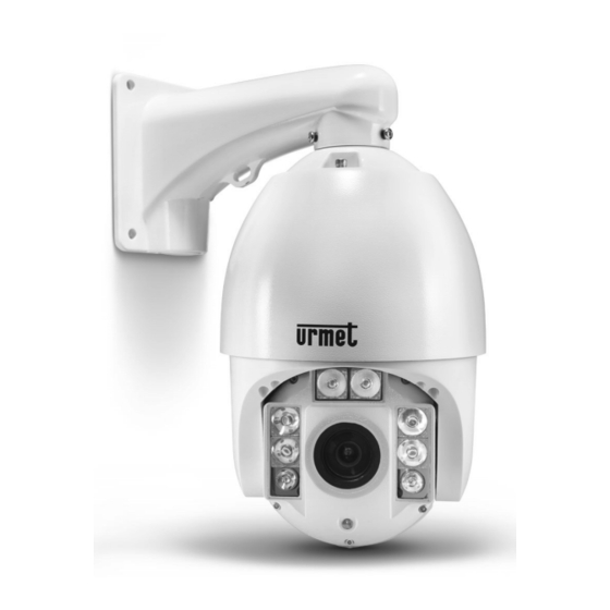
- Page 1 Mod. 1092 DS1092-229 EASY DOME CAMERA AHD 20X WITH IR ILLUMINATOR Ref.1092/679 USER AND INSTALLATION MANUAL...
-
Page 2: Table Of Contents
ENGLISH TABLE OF CONTENTS General Information ..........................3 Product description ......................... 3 1.1.1 General features ..........................3 Important safety notes ........................... 4 Opening the box ............................. 6 3.1.1 Contents of the box ..........................6 Installation procedure ..........................6 Easy Dome minimum configuration ..................6 4.1.1 Wall installation ............................ -
Page 3: General Information
Dear Customer, Thank your for purchasing this product. This document shows how to install and use the URMET Domus Easy Dome 20X Ref.1092/679. Read this manual which contains information for correct, safe use carefully. Keep this manual at hand so that you can refer to it when needed. -
Page 4: Important Safety Notes
IMPORTANT SAFETY NOTES The following important notes must be followed carefully to work the Ref.1092/679 camera and respective accessories in total safety. The term “video system” here means a camera and all components needed for its operation (e.g., power, leads, supports, control board and more). - Page 5 In this case, only use the controls described in the manual because improper use of other controls could make the situation worse. More work may be required by the qualified technician to restore normal working conditions of the device. If the device was dropped, subjected to heavy shocks or if the camera packaging was damaged. If the device performance changes considerably.
-
Page 6: Opening The Box
Accessories may be changed without prior notice. INSTALLATION PROCEDURE This section contain detailed instructions for installing Urmet Domus 1092/679. These instructions assume that the installer has a good knowledge of installation techniques and is capable of adopting safe installation methods. -
Page 7: Wall Installation
4.1.1 WALL INSTALLATION Identify the camera installation point and proceed as follows: Include a connection box for making connections and fitting the power unit, if required. Drill holes according to the type of wall (cement, wood, etc.) and the fastening devices used. If the type of installation includes laying of cables in sight, unscrew the plug on the lower part of the bracket with a slot type screwdriver and insert all the functioning cable of the dome inside the bracket, providing a suitable protection conduit for the cables. -
Page 8: Wall Installation With Power Box Ip66 Ref. 1092/708
4.1.2 WALL INSTALLATION WITH POWER BOX IP66 REF. 1092/708 Identify the camera installation point and proceed as follows: Drill holes according to the type of wall (cement, wood, etc.) and the fastening devices used. Fasten the connection box to the wall, making sure that the wire grommets are facing downwards. Open the Power Box by unscrewing the four screws on the cover corners. -
Page 9: Cables Specifications
Fix the the barcket of the Easy Dome to the Power Box (wth 4 screws and 8 washers available with the Power Box) Take the cable supplied withe the Dome off Connect the cable coming from the bracket to the Dome connector Fix the glass to to the housing screwing the 3 screws Open the metal cover inside the plastic housing to find the configuration switch. -
Page 10: Operation At Power-Up
The camera will run a calibration procedure and a message showing the following information will appear on the video output OSD (On Screen Display): protocol, communication parameters, camera address and software version. EASY DOME 1092/679 CAMERA: CTU20AM108 ADDRESS: 1 BAUDRATE: 2400 PROTOCOL: AUTO VERSION: 1.0... -
Page 11: Control Keypad Command Types
Control keypad command syntax Controls can use the joystick, single keys or key combinations. The key command syntax is shown below. Key command syntax The syntax used in this manual for controls using keys consists of various elements (words and three digit numbers). Each command is always in braces and each element is separated by commas. -
Page 12: Select Camera
SELECT CAMERA The camera to be controlled must be selected first. For example, the following command selects camera 1: 1 + CAM (1092/621) ADDR + 1 + ENTER (1092/693) After this operation, the message CAM 1 will appear on the control panel display. CAMERA MOTIONS After selecting a camera, it can be moved either directly using the control panel as described below: −... -
Page 13: Focusing Functions
The subject is too big. 5.4.4 IRIS OPENING FUNCTIONS The iris cannot be manually open in the Easy Dome 1092/679. 5.4.5 PRESET POSITIONS PROGRAM AND RECALLING The Easy Dome 20X camera can store up to 128 panning, tilting and zooming configurations (called preset positions) which can be recalled at any time. -
Page 14: Function Programming Menu
FUNCTION PROGRAMMING MENU Use the following 1092/621 - 1092/693 control panel command to access the function programming menu. 95 + SHOT (1092/621) SHOT + 95 (+ ENTER) (1092/693) At this point, if no password is required for access, the following first level menu will appear on the screen: EASY IV 1092/679 1 Language English... -
Page 15: Product Information Menu
5.5.1 PRODUCT INFORMATION MENU In the first level menu, select <DOME INFORMATION> to display information concerning the protocol, the camera address, the presetting number, the language of use and the measured temperature EASY DOME IV 1092/679 Dome Hard ID: 1 Baudrate: 2400 none Protocol:... -
Page 16: Camera Configuration Menu (Control Options) - Settings Of Dome
5.5.3 CAMERA CONFIGURATION MENU (CONTROL OPTIONS) – SETTINGS OF DOME From the first level menu, choice <CONTROL OPTIONS> to select the options concerning dome displaying modes and motions. CONTROL OPTIONS 1 Dome Addr Setup 2 Auto Flip 3 Proportional Spd 4 Pan Reverse 5 Tilt Reverse 6 V Scan Still... - Page 17 If active with ON, the Dome tilt limit increases of 5 degrees, going + 5 TILT LIMIT ON/OFF from 90° to 95°. If active with ON, limits Dome speed of movement to half the SPEED LIMIT ON/OFF maximum speed. It permits to set the modes for the IR illumination IRLED CONTROL Closes OSD menu RETURN...
-
Page 18: Dome Addr Setup Submenu Of Control Options Menu
5.5.4 DOME ADDR SETUP SUBMENU OF CONTROL OPTIONS MENU DOME ADDR SETUP 1 Dome ID Mode HARD ID 2 Input soft id 3 Input S/N 00000000 4 S/N 78648108 5 IRIS- to Save Exit 6 FOCUS- to Exit Option Value Explanation When ADDRESS TYPE is HARD, the address is assigned by setting the dip-switches present on the... -
Page 19: Camera Options Menu
5.5.5 CAMERA OPTIONS menu From the first level menu, select <CAMERA OPTIONS> to choose the functions to change the dome lens parameters. CAMERA OPTIONS 1 Zoom and Focus 2 Camera Exposure 3 Others 4 Return Option Value Explanation Zoom/Focus settings submenu (see below) ZOOM AND FOCUS Camera module exposure settings submenu (see below) CAMERA EXPOSURE... - Page 20 Option Value Explanation In this mode: The shutter opening time cannot be set and is automatically adjusted. AUTO Autoiris opening is automatically adjusted. Gain control is automatic (AGC ON). In this mode: The shutter opening time may be varied as programmed in the ”...
- Page 21 OTHERS submenu OTHERS 1 Sharpness 2 BLC 3 WB Mode Auto 4 R Gain Auto 5 B Gain Auto 6 V-Mirror PAGINA 2 7 H-Mirror 8 D/N Mode Auto 9 Stabilization 10Noise Reduction 11Function OSD 12Motion Detect 13WDR Return Option Value Explanation The sharpness of the image may be adjusted automatically...
-
Page 22: Function Programming Menu - Setting For The Functions Available On The Dome
5.5.6 FUNCTION PROGRAMMING MENU – SETTING FOR THE FUNCTIONS AVAILABLE ON THE DOME From the first level menu, choose <FUNCTION PROGRAMMING> to select the functions available on the dome. FUNCTION PROGRAM 1 Preset 2 VectorScan 3 Pattern 4 Sector Setup 5 Mask Zone Setup 6 Motion 7 Auto Scan Setup... - Page 23 5.5.6.2 PROGRAM VECTORSCAN submenu of FUNCTION PROGRAMMING menu The VectorScan function allows to program video surveillance sequences (VectorScan), composed by different Presets, Pattern or also other VectorScan created before, with programmable movement speed between positions and dwelling time. VECTORSCAN 1 Number 2 Program a VectorScan 3 Run a VectorScan 4 Delete a VectorScan...
- Page 24 5.5.6.3 PATTERN submenu of FUNCTION PROGRAM menu A Pattern is a sequence of movements and functions that can be stored and repeated by a command of an operator or automatically. PROGRAM VECTORSCAN 1 Number 2 Program 3 Run 4 Delete 5 Name ------ 6 Name Display...
- Page 25 Option Value Explanation This option allows to select the zone where to enter a descriptive text. This operation is allowed for 8 zones max. With the joystick, NUMBER set the preset number to be stored. This option allows to define the PAN start position. With the joystick select the zone start position and confirm with IRIS-.
-
Page 26: Park Action Submenu Of Motion Submenu
5.5.7 PARK ACTION SUBMENU OF MOTION SUBMENU PARK ACTION 1 Action Preset 2 Number 3 Delay 4 Operattion 6 Return Option Value Explanation Allows to select the action to be carried out after power on. Please note: the selected action will be carried out only if NONE/PRESET/VECTORSCAN/ PARK ACTION (see previous settings) is different from ACTION... -
Page 27: Power On Action Submenu Of Motion Submenu
5.5.8 POWER ON ACTION SUBMENU OF MOTION SUBMENU POWER ON ACTION 1 Action 2 Number 3 Return Option Value Explanation NONE/PRESET/VECTORSCAN/ This option allows to select the action to be activated. ACTION PATTERN/PANSCAN/AUTOSCAN This option allows to define in detail which single action has to be activated. -
Page 28: Auto Scan Setup Submenu Of Function Program
5.5.10 AUTO SCAN SETUP SUBMENU OF FUNCTION PROGRAM This function determines a continuous rotation of the camera. AUTO SCAN SETUP 1 Auto Scan Pos Set 2 Speed 3 Direction Left 4 Run 5 Return Option Value Explanation Allows to memorize the coordinates before starting PAN and AUTO SCAN POS SET TILT function. - Page 29 5.5.11.1 ALARM PROGRAMMING SUBMENU OF FUNCTION PROGRAM This menu allows the selection of the alarms enabled with the additional remote alarm system. After selecting one option the specific menu will be displayed. ALARM PROGRAMMING 1 Number 2 Name ----- 3 Name Display 4 Channel Enable 5 Action Preset...
-
Page 30: System Setup Programming Menu - Authorization Settings For Camera Usage
5.5.12 SYSTEM SETUP programming menu – authorization settings for camera usage. To use this menu you have to enter a password. This password is a numeric combination (max 6 digits). The password digits are selected by moving the joystick horizontally. The "▲" symbol indicates the digit that will be entered. - Page 31 Option Value Explanation This option allows to edit a first level password (max. MASTER SETUP authorization level) (see below). This option allows to edit a second level password (see OPERATOR SETUP below). This option allows to define which operations can be performed by the operator and which ones are forbidden (see AUTHORIZATION below).
- Page 32 OPERATOR SETUP submenu of SYSTEM SETUP menu GUEST SETUP 1 Password Edit 2 Operation Lock OFF 3 Wait Option Value Explanation This option allows to edit a second level password that enables or disables options and functions available for the PASSWORD EDIT dome.
-
Page 33: Setup Of The Dome
SETUP OF THE DOME Here are the parameters about Protocol and Baud Rate. Address Baud Rate Dip Switch Dip Switch Protocol Baud rate Auto 2400 DYNACOLOR 4800 9600 19200 DS1092-229... - Page 34 Always use the “AUTO” protocol. Using the compatible products in the Urmet Domus catalogue, it is advisable to select PELO-D protocol at 2400 bps baud rate to ensure the correct operation of the Easy Dome 20X. In this case, the PELCO D protocol will be automatically recognized.
-
Page 35: Special Control Panel Commands Ref.1092/621 - 1092/693
SPECIAL CONTROL PANEL COMMANDS REF.1092/621 - 1092/693 The Easy Dome 20X camera can be programmed and operated using various quick control panel commands. To use them press the buttons (keyboard 1092/621 / keyboard 1982/693) in the sequence indicated in the following table. - Page 36 171+SHOT/SHOT+171+ENTER Simulates the N° 1 alarm input activation 172+SHOT/SHOT+172+ENTER Simulates the N° 2 alarm input activation 173+SHOT/SHOT+173+ENTER Simulates the N° 3 alarm input activation 174+SHOT/SHOT+174+ENTER Simulates the N° 4 alarm input activation 175+SHOT/SHOT+175+ENTER Simulates the N° 5 alarm input activation 176+SHOT/SHOT+176+ENTER Simulates the N°...
-
Page 37: Specification
SPECIFICATION The main technical features of the 1092/679 cameras are summarised below. General features Value Camera module Sony CMOS IMX238 1/2.8” 720p / 1080p Resolution Sensitivity (lux) 0.2 Lux color / 0.02Lux B/W, F1.6 IR Cut mechanic filter Lens Value Optical Zoom 20X, f=3.5mm –... - Page 38 Mechanical characteristics Value Installation Wall mounted, bracket included Horizontal rotation angle/speed 360° (continuous) / 180°/s Vertical rotation angle/speed 0° - 90° (Flip) / 100°/s Horizontal rotation speed /°sec. 200°/s Proportional moving speed Available Auto flip Waterproof level IP66 Remote control Value Interface RS485...
Need help?
Do you have a question about the Easy Dome 1092/679 and is the answer not in the manual?
Questions and answers