Allen-Bradley Stratix 8300 User Manual
Ethernet managed switches
1783-ms06t,1783-ms10t,1783-rms06t,1783-rms10t,1783-mx08t, 1783-mx08f
Hide thumbs
Also See for Stratix 8300:
- Manual (14 pages) ,
- User manual (548 pages) ,
- Installation instructions manual (20 pages)

Subscribe to Our Youtube Channel
Related Manuals for Allen-Bradley Stratix 8300


Summary of Contents for Allen-Bradley Stratix 8300
- Page 1 User Manual Stratix 8000 and Stratix 8300 Ethernet Managed Switches Catalog Numbers 1783-MS06T, 1783-MS10T, 1783-RMS06T, 1783-RMS10T, 1783-MX08T, 1783-MX08F...
-
Page 2: Important User Information
Identifies information that is critical for successful application and understanding of the product. IMPORTANT Allen-Bradley, Rockwell Automation, RSLinx, RSLogix 5000, RSNetWorx, Stratix 8000, Stratix 8300, and TechConnect are trademarks of Rockwell Automation, Inc. Trademarks not belonging to Rockwell Automation are property of their respective companies. -
Page 3: Summary Of Changes
These changes are associated with CIP revision 6.001, IOS Image 15.0(2)SEIES of the Stratix 8000 and Stratix 8300 Ethernet Managed Switches. New and Updated This table contains the changes made to this revision. -
Page 4: Rockwell Automation Publication 1783-Um003G-En-P - December
Summary of Changes Notes: Rockwell Automation Publication 1783-UM003G-EN-P - December 2012... -
Page 5: Table Of Contents
Introduction........... . . 11 Stratix 8000 and Stratix 8300 Ethernet Managed Switches and Related Products. - Page 6 REP Open Segment ......... . . 41 REP Ring Segment.
- Page 7 Dashboard Dialog Box..........89 Switch Information.
- Page 8 Chapter 5 Troubleshoot the Switch Introduction ........... . 139 Run a Diagnostic Test .
-
Page 9: Preface
About This Publication This publication describes the embedded software features and tools for configuring and managing the Stratix 8000 and Stratix 8300 Ethernet Managed Switches with the RSLogix 5000 software Add-on Profile (AOP), or the Device Manager Web interface. In addition, this publication provides troubleshooting information to help you resolve basic switch and network issues. -
Page 10: Additional Resources
To order paper copies of technical documentation, contact your local literature Allen-Bradley distributor or Rockwell Automation sales representative. Other manuals that may be of use to you are available at http://www.Cisco.com. These include the following: • Cisco IE-3000 Command Line Reference Manual •... -
Page 11: Getting Started
(PLCs), human-machine interfaces (HMIs), drives, sensors, and I/O. The Stratix 8000 Ethernet Managed Switch is a Layer 2 switch. The Stratix 8300 Ethernet Managed Switch adds Layer 3 routing to the Stratix 8000 switch The Stratix 8300 switch contains all the features of the Stratix 8000 switch, plus a number of IP routing protocols, along with enhanced security and QoS features. -
Page 12: Stratix 8000 And Stratix 8300 Ethernet Managed Switches And Related
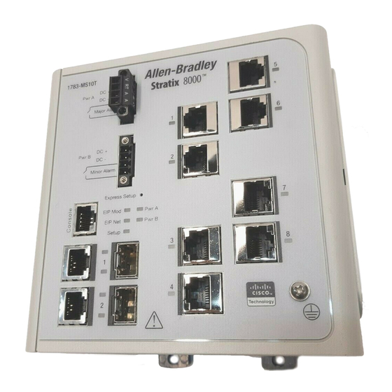
Cat. No. Description 1783-MCF Stratix 8000 CompactFlash card (spare) 1783-RMCF Stratix 8300 CompactFlash card (spare) Cryptographic IOS Cat. No. Description 1783-MCS Cryptographic IOS for Stratix 8000 switches 1783-RMCS Cryptographic IOS for Stratix 8300 switches Rockwell Automation Publication 1783-UM003G-EN-P - December 2012... - Page 13 Getting Started Chapter 1 The switch front panel contains the ports, the status indicators, and the power and relay connectors. The following figures show the 1783-MS10T switch and expansion module front panels. Figure 1 - 1783-MS10T Switch Power and relay connectors Console port Dual-purpose ports 10/100 ports...
-
Page 14: Hardware Features
Figure 3 - 1783-MX08F Switch Fiber Expansion Module 31797-M 100BASE-FX ports Hardware Features These features are common to both the Stratix 8000 and Stratix 8300 switches. See the figures on pages 13…14 for an illustration of these features. Hardware Features... -
Page 15: Compactflash Memory Card
Getting Started Chapter 1 Hardware Features Feature Description 100BASE-FX ports The IEEE 802.3-2002 100BASE-FX ports (on the 1783-MX08F expansion module) provide Full-duplex 100 Mbps connectivity over multi-mode fiber (MMF) cables. These ports use a built-in, small-form- factor fixed (SFF) fiber-optic transceiver module that accepts a dual LC connector. The cable can be up to 2 km (1.24 mi.) in length. - Page 16 Chapter 1 Getting Started • A straight-through or crossover Category 5 Ethernet cable to connect your personal computer to the switch Do the following to configure your computer: • Disable any wireless interface running on your personal computer. • Disable other networks in your system. •...
- Page 17 Getting Started Chapter 1 6. While the Setup status indicator flashes green, start an Internet browser session on the personal computer and navigate to http://169.254.0.1/express-setup.htm. If you have a home page configured, the switch configuration will load instead of your normal home page. The switch prompts you for the default switch username and password.
- Page 18 Chapter 1 Getting Started Field Description Management Interface (VLAN ID) The name and ID of the management VLAN through which the switch will be managed. Select an existing VLAN to be the management VLAN. The default ID is 1. The default name for the management VLAN is default. The number can be from 1…1001. Be sure that the switch and your network management station are in the same VLAN.
- Page 19 Getting Started Chapter 1 11. Enter the optional settings now, or enter them later by using the Device Manager web interface. In this field Do this Host Name A name for the switch. The name can have up to 31 alphanumeric characters. The name cannot contain a ?, a space, or a tab. The default is Switch.
-
Page 20: Switch Memory Allocation
Chapter 1 Getting Started Switch Memory Allocation The following table provides details on default memory allocation for the switches. You can use SDM templates to configure system resources in the switch to optimize support for specific features, depending on how the switch is used in the network. -
Page 21: Hardware Requirements
Getting Started Chapter 1 You can display the Device Manager Web interface from anywhere in your network through a Web browser such as Microsoft Internet Explorer. Hardware Requirements Attribute Requirement Processor speed 233 MHz min 1 GHz recommended 512 MB min 1 GB recommended Free hard drive space 50 MB... -
Page 22: Rslogix 5000 Software Interface
Chapter 1 Getting Started RSLogix 5000 Software You can manage the switch by using the RSLogix 5000 software to configure and monitor the switch. RSLogix 5000 software is an IEC 61131-3 compliant Interface software package that offers relay ladder, structured text, function block diagram, and sequential function chart editors for you to develop application programs. -
Page 23: Command Line Interface
Getting Started Chapter 1 Command Line Interface You can manage the switch from the command-line interface (CLI) by connecting your personal computer directly to the switch console port or through the network by using Telnet. Follow these steps to access the CLI through the console port. 1. - Page 24 Chapter 1 Getting Started Notes: Rockwell Automation Publication 1783-UM003G-EN-P - December 2012...
-
Page 25: Switch Software Features
Chapter Switch Software Features Introduction The Stratix 8000 and Stratix 8300 switches contain common Ethernet software features, unless otherwise specified. Topic Page Port Numbering Global Macro Smartports VLANs IGMP Snooping With Querier Spanning Tree Protocol Storm Control Port Security EtherChannels... -
Page 26: Port Numbering
Chapter 2 Switch Software Features Port Numbering The port ID consists of port type (Gigabit Ethernet for Gigabit ports and Fast Ethernet for 10/100 Mbps ports), unit number (1, 2, or 3) and port number (1-2 for Gigabits, 1-4 for the 6 port base and 1-8 for all others). Gigabit Ethernet is abbreviated as Gi and Fast Ethernet as Fa. -
Page 27: Global Macro
Switch Software Features Chapter 2 Global Macro Once you complete Express Setup (refer to Set Up the Switch Initially with Express Setup on page 15), a global macro (macro name: ab-global) will execute. This macro configures the switch for typical industrial automation applications using the EtherNet/IP protocol. - Page 28 Chapter 2 Switch Software Features By default, the switch ports are set with the No (None) port role. Port Roles Port Role Description Apply this role to ports to be connected to EtherNet/IP (Ethernet Industrial Protocol) devices. It can be used for industrial automation devices, such as logic controllers and I/O. •...
-
Page 29: Avoid Smartports Mismatches
Switch Software Features Chapter 2 Avoid Smartports Mismatches A Smartports mismatch occurs when an attached device does not match the Smartports role applied to the switch port. Mismatches can have adverse effects on devices and your network. Mismatches can result in the following conditions: •... -
Page 30: Isolate Traffic And Users
Chapter 2 Switch Software Features Isolate Traffic and Users By using VLANs, you can isolate different types of traffic (such as voice and data) to preserve the quality of the transmission and to minimize excess traffic among the logical segments. You can also use VLANs to isolate different types of users. For example, you can restrict specific data broadcasts to specific logical workgroups for security purposes, such as keeping information about employee salaries only on devices in a VLAN created for payroll-related communication. -
Page 31: Isolate Different Traffic Types
Switch Software Features Chapter 2 Isolate Different Traffic Types Isolating data traffic from delay-sensitive traffic, such as voice traffic, ensures the quality of the voice transmission. In the figure on page 30, VLANs in a Stratix 8000 Switch Network, switch ports connected to the IP phones belong to VLAN 3, a VLAN that is configured to provide Voice over IP (VoIP) services on these connections, meaning priority is given to voice traffic over regular IP data traffic. -
Page 32: Igmp Snooping With Querier
The default number of multicast groups allowed in the switches is as follows: • Stratix 8000 switch: 256 • Stratix 8300 switch: 1024 You can modify the number of multicast groups supported by using the command line interface. If you have over 180 multicast groups on a Stratix 8000 we suggest modifying the number of multicast groups by changing the SDM template to the lanbase routing template. -
Page 33: Spanning Tree Protocol
Switch Software Features Chapter 2 Spanning Tree Protocol Spanning Tree Protocol (STP) is a Layer 2 link management protocol that provides path redundancy while preventing loops in the network. For a Layer 2 Ethernet network to function properly, only one active path can exist between any two stations. -
Page 34: Storm Control
Chapter 2 Switch Software Features Storm Control Storm control prevents traffic on a LAN from being disrupted by a broadcast, multicast, or unicast storm on one of the physical interfaces. A LAN storm occurs when packets flood the LAN, creating excessive traffic and degrading network performance. -
Page 35: Default Storm Control Configuration
Switch Software Features Chapter 2 Figure 5 - Storm Control Example Forwarded Traffic Blocked Traffic Total number of Threshold broadcast packets or bytes Time The combination of the storm-control suppression level and the 1-second time interval controls the way the storm control algorithm works. A higher threshold lets more packets pass through. -
Page 36: Static Secure Mac Address (Mac Id)
Chapter 2 Switch Software Features If the link becomes inactive, the switch will dynamically relearn the MAC ID to be secured. The following table shows the Smartport role and the maximum allowable MAC IDs. Smartport Role Number of MAC IDs (max) Automation Device Desktop for Automation Switch for Automation... -
Page 37: Etherchannels
Switch Software Features Chapter 2 When a violation occurs, the port goes into the Restrict mode. In this mode, packets with unknown source addresses are dropped and you are notified that a security violation has occurred. An SNMP trap is sent, a syslog message is logged, and the violation counter increments. - Page 38 Chapter 2 Switch Software Features Figure 6 - EtherChannels between Stratix 8000 Switches You can configure an EtherChannel in one of these modes: Port Aggregation Protocol (PAgP), Link Aggregation Control Protocol (LACP), or On. Configure both ends of the EtherChannel in the same mode. •...
-
Page 39: Dhcp Persistence
Switch Software Features Chapter 2 DHCP Persistence Every device in an IP-based network must have a unique IP address. The Dynamic Host Configuration Protocol (DHCP) automatically assigns IP address information from a pool of available addresses to newly connected devices (DHCP clients) in the network. - Page 40 Chapter 2 Switch Software Features You can construct almost any type of network based on REP segments. REP also supports VLAN load-balancing, controlled by the primary edge port but occurring at any port in the segment. These types of REP ports are selectable in the Device Manager Web interface: •...
-
Page 41: Rep Open Segment
Switch Software Features Chapter 2 REP Open Segment The segment shown below is an open segment; there is no connectivity between the two edge ports. The REP segment cannot cause a bridging loop and it is safe to connect the segment edges to any network. All hosts connected to switches inside the segment have two possible connections to the rest of the network through the edge ports, but only one connection is accessible at any time. -
Page 42: Access Ring Topologies
Chapter 2 Switch Software Features REP segments have these characteristics: • If all ports in the segment are operational, one port (referred to as the alternate port) is in the blocked state for each VLAN. • If VLAN load balancing is configured, two ports in the segment control the blocked state of VLANs. -
Page 43: Link Integrity
Switch Software Features Chapter 2 You should configure REP only in networks with redundancy. Configuring REP in a network without redundancy causes loss of connectivity. Link Integrity REP does not use an end-to-end polling mechanism between edge ports to verify link integrity. -
Page 44: Supported Mibs
• Confidential information, for example, SNMP Set command packets that change a router configuration, can be encrypted to prevent the contents from being exposed on the network. Supported MIBs The following MIBs are supported by the Stratix 8000 and Stratix 8300 switches. BRIDGE-MIB (RFC1493) CISCO-BULK-FILE-MIB CISCO-BRIDGE-EXT-MIB... - Page 45 Switch Software Features Chapter 2 CISCO-ENVMON-MIB CISCO-ETHERNET-ACCESS-MIB CISCO-FLASH-MIB CISCO-FTP-CLIENT-MIB CISCO-HSRP-MIB CISCO-HSRP-EXT-MIB CISCO-IGMP-FILTER-MIB CISCO-IETF-IP-MIB CISCO-IETF-IP-FORWARD-MIB CISCO-L2L3-INTERFACE-CONFIG-MIB CISCO-LAG-MIB CISCO-IMAGE-MIB CISCO-MAC-NOTIFICATION-MIB CISCO-MEMORY-POOL-MIB CISCO-PAE-MIB CISCO-PAGP-MIB CISCO-PING-MIB CISCO-PORT-SECURITY-MIB CISCO-PORTSTORM-CONTROL-MIB CISCO-PORT-QOS-MIB CISCO-PRIVATE-VLAN-MIB CISCO-PROCESS-MIB CISCO-RTTMON-MIB CISCO-STACK-MIB CISCO-STP-EXTENSIONS-MIB Rockwell Automation Publication 1783-UM003G-EN-P - December 2012...
- Page 46 Chapter 2 Switch Software Features CISCO-SYSLOG-MIB CISCO-TCP-MIB CISCO-UDLDP-MIB CISCO-VLAN-IFTABLE-RELATIONSHIP-MIB CISCO-VLAN-MEMBERSHIP-MIB CISCO-VTP-MIB ENTITY-MIB (RFC2737) ETHERLIKE-MIB (RFC1398) IEEE8023-LAG-MIB IEEE8021-PEA-MIB IF-MIB (RFC1573) IGMP-MIB IPMROUTE-MIB OSPF-MIB (RFC1253) OLD-CISCO-CHASSIS-MIB OLD-CISCO-INTERFACES-MIB OLD-CISCO-IP-MIB OLD-CISCO-SYS-MIB OLD-CISCO-TS-MIB PIM-MIB MIB-II (RFC1213) RMON-MIB (RFC1757) RMON2-MIB (RFC2021) SNMP-FRAMEWORK-MIB (RFC2571) SNMP-MPD-MIB (RFC2572) Rockwell Automation Publication 1783-UM003G-EN-P - December 2012...
-
Page 47: Port Mirroring
The Stratix 83000 Ethernet Managed Switch uses IP address routing to map subnetworks (subnets) to an individual VLAN. In some network environments, (Stratix 8300 Switch Only) VLANs are associated with individual networks or subnetworks. In an IP network, each subnetwork is mapped to an individual VLAN. Configuring VLANs helps control the size of the broadcast domain and keeps local traffic local. -
Page 48: Types Of Routing
The Layer 3 switch checks the routing table, finds the correct outgoing interface, and forwards the packet on the VLAN 20 interface to Switch B. Switch B receives the packet and forwards it to Host C. Types of Routing Stratix 8300 switches can route packets by using these methods. Routing Feature Description... -
Page 49: Static Routing
Static Routing Static routing is implemented both on the Stratix 8000 and Stratix 8300 switches. Static routing is a Layer 3 (IP) protocol that lets the user to manually define routes between Layer 3 devices (routers and switches). When static routing is... -
Page 50: Alarms
– Port not operating – Frame Check Sequence (FCS) bit error rate Cryptographic IOS The Stratix 8000 and Stratix 8300 cryptographic IOS (available as a separate catalog number for downloading) provides network security by encrypting Software (Optional) administrator traffic during Telnet and SNMP sessions. The cryptographic IOS supports all features of the standard IOS, as well as these protocols: •... -
Page 51: Manage The Switch Via The Device Manager Web Interface
Chapter Manage the Switch via the Device Manager Web Interface Introduction After you complete Express Setup, you can manage the switch by using the Device Manager Web interface (supplied with the switch). On all dialog boxes accessible from the Configure menu, when you click Submit, changes are applied to the switch and stored on the CompactFlash card. -
Page 52: Access The Device Manager Web Interface
Chapter 3 Manage the Switch via the Device Manager Web Interface Access the Device Follow these steps to use the Device Manager Web interface to configure and monitor the switch. Manager Web Interface 1. Launch a Web browser on your personal computer or workstation. 2. -
Page 53: Front Panel View And Status Indicators
Manage the Switch via the Device Manager Web Interface Chapter 3 Front Panel View and The Front Panel view is a graphical display of the front panels of the base switch and attached switch expansion modules, and it is always visible during the Device Status Indicators Manager Web interface session. - Page 54 Chapter 3 Manage the Switch via the Device Manager Web Interface Status Indicators Indicator Status Description Pwr A and The Pwr status indicators show the DC power status. Pwr B Power to the switch is off or is not properly connected. Solid green Power is present.
- Page 55 Manage the Switch via the Device Manager Web Interface Chapter 3 Status Indicators Indicator Status Description Status In this mode, the port status indicators show the status of the ports. This is the default mode. No link Solid green No activity on link. Flashing green Link activity.
-
Page 56: Status Field
Chapter 3 Manage the Switch via the Device Manager Web Interface • The Smartport type and VLAN type and name are displayed when Smartport Port mode is selected. • The Uptime field shows how long the switch has been operating since it was last powered on or was restarted. -
Page 57: Assign Port Roles
Manage the Switch via the Device Manager Web Interface Chapter 3 Assign Port Roles Use the Smartports dialog box to assign port roles to the switch ports. Follow these guidelines when using Smartports: • Before using Smartports, decide which switch port will be connected to which device type. -
Page 58: Customize Port Role Attributes
Chapter 3 Manage the Switch via the Device Manager Web Interface To assign a Smartport role, follow this procedure. 1. Choose Configure >Smartports from the Device Manager Web interface menu. 2. Select the port role. 3. Click the desired port to which you want to apply the Smartport. 4. - Page 59 Manage the Switch via the Device Manager Web Interface Chapter 3 Use the Port Settings dialog box to change basic port settings. To display this dialog box, choose Configure>Port Settings from the Device Manager Web interface menu. The following table lists the basic settings for the switch ports. Port Settings Setting Description...
- Page 60 Chapter 3 Manage the Switch via the Device Manager Web Interface Port Settings Setting Description Speed The operating speed of the switch port. Choose the speed from the pull-down menu. You can choose Auto (autonegotiation) if the connected device can negotiate the link speed with the switch port. The default is Auto. We recommend that you use the default so that the speed setting on the switch port automatically matches the setting on the connected device.
-
Page 61: Configure Ports To Use Quickconnect Technology
Configure Ports to Use QuickConnect Technology EtherNet/IP QuickConnect technology enables EtherNet/IP devices to quickly power up and join an EtherNet/IP network. The Stratix 8000 and Stratix 8300 switches can be an integral part of a network configuration that uses QuickConnect technology. To use the switches in a network that supports QuickConnect technology, you must apply certain port settings to the switch. - Page 62 Chapter 3 Manage the Switch via the Device Manager Web Interface The following tables show switch network settings displayed on the Express Setup dialog box. Switch Network Settings Setting Description Management Interface The name and ID of the management VLAN through which the switch will be managed. Select an existing VLAN to be the (VLAN ID) management VLAN.
-
Page 63: Configure Vlans
Manage the Switch via the Device Manager Web Interface Chapter 3 CIP VLAN Settings Setting description CIP VLAN The VLAN on which CIP will be enabled. The CIP VLAN can be the same as the management VLAN or you can isolate CIP traffic on another VLAN that is already configured on the switch. - Page 64 Chapter 3 Manage the Switch via the Device Manager Web Interface After creating VLANs, you can then assign the appropriate ports to those VLANs. Before assigning ports to VLANs, make sure that each port is applied with the appropriate port role. Rockwell Automation Publication 1783-UM003G-EN-P - December 2012...
-
Page 65: Assign Ports To Vlans
Manage the Switch via the Device Manager Web Interface Chapter 3 Assign Ports to VLANs To display this dialog box, choose Configure>Smartports from the Device Manager Web interface menu, and click Customize on the Smartports dialog box. Advanced VLAN Configuration The advanced VLAN options are the Rapid Spanning Tree Protocol (RSTP) and the Internet Group Management Protocol (IGMP) snooping features on the switch ports. - Page 66 Chapter 3 Manage the Switch via the Device Manager Web Interface With IGMP snooping, only ports that are members of specific IP multicast groups receive multicast messages. The result is a more efficient use of bandwidth. Use the VLANs Advanced dialog box to change the RSTP and IGMP snooping settings.
-
Page 67: Configure Snmp
Manage the Switch via the Device Manager Web Interface Chapter 3 Enable SNMP if you plan to have the switch managed through another network Configure SNMP management application. By default, SNMP is disabled. Other general SNMP settings include the name of the switch or the network administrator and the switch location. -
Page 68: Use Snmp Management Applications
Chapter 3 Manage the Switch via the Device Manager Web Interface Click the Community Strings tab to display the Community Strings dialog box. Enable SNMP must be unchecked so that the Community Strings tab appears. • The Read-Only community string enables the switch to validate Get (read- only) requests from a network management station. -
Page 69: Configure Etherchannels
Manage the Switch via the Device Manager Web Interface Chapter 3 Configure EtherChannels You can create up to six EtherChannels, and you can configure each EtherChannel in one of these modes. • IEEE 802.3ad (LACP) mode (default) This lets the switch create one end of the EtherChannel if the other switch requests it. - Page 70 Chapter 3 Manage the Switch via the Device Manager Web Interface See the Device Manager Web interface online help for additional guidelines and procedures. All ports in an EtherChannel must have the same characteristics. • All are either 10/100 ports, or all are 10/100/1000 ports. You cannot group a mix of 10/100 and 10/100/1000 ports in an EtherChannel.
-
Page 71: Configure Dhcp Persistence
Manage the Switch via the Device Manager Web Interface Chapter 3 Configure DHCP To use DHCP persistence, you must first enable DHCP and set up the IP address pool. Then you must assign a specific IP addresses to each port. Persistence Set up the DHCP Server To enable or disable the DHCP Server mode on the switch, do the following. - Page 72 Chapter 3 Manage the Switch via the Device Manager Web Interface 3. Enter DHCP server settings, as appropriate. DHCP Server Settings Setting Description Enable DHCP This option enables the DHCP Server globally for the switch. When the DHCP server is enabled and one or more pools are created, the switch will serve IP addresses to clients on the network.
-
Page 73: Configure A Dhcp Ip Address Pool
Manage the Switch via the Device Manager Web Interface Chapter 3 Configure a DHCP IP Address Pool Once DHCP is enabled, you can create the DHCP address pool from the DHCP dialog box. 1. Click Create. 2. Enable DHCP snooping on a specific VLAN. 3. - Page 74 Chapter 3 Manage the Switch via the Device Manager Web Interface DHCP Address Pool Settings Setting Description Ending IP Address The ending IP address that defines the range of addresses in the DHCP IP address pool. The format is a 32-bit numeric address written as four numbers separated by periods.
-
Page 75: Reserve Ip Addresses Through Dhcp Persistence
DHCP snooping on the appropriate VLAN. Doing this blocks the broadcast of this DHCP request so that no other server (including another Stratix 8000 or Stratix 8300 switch with DHCP persistence enabled) will respond. If you are using DHCP persistence, we recommend that you initially assign static IP addresses to end devices. - Page 76 Chapter 3 Manage the Switch via the Device Manager Web Interface The following figure and chart illustrate DHCP persistence behavior. Switch 1 Switch 2 FA4 FA5 FA6 FA8 FA1 FA2 FA3 FA7 DHCP Persistence Behavior Then • Switch 1 has ports FA1…FA3 in its persistence table A new device connected to switch 1 FA1 receives an IP address from the Switch 1 •...
- Page 77 Manage the Switch via the Device Manager Web Interface Chapter 3 Use the DHCP Persistence dialog box to assign, modify, or delete a switch port IP address. 1. Click the DHCP Persistence tab. 2. Enter DHCP Persistence settings, as appropriate. DHCP Persistence Settings Setting Description...
-
Page 78: Synchronize The Switch With Other Devices Via Ptp
Chapter 3 Manage the Switch via the Device Manager Web Interface Synchronize the Switch The IEEE 1588 standard defines a protocol, called Precision Time Protocol, or PTP, which enables precise synchronization of clocks in measurement and with Other Devices via PTP control systems. -
Page 79: Set The Synchronization Clock Mode
Manage the Switch via the Device Manager Web Interface Chapter 3 Set the Synchronization Clock Mode Follow this procedure to set the Synchronization Clock mode. 1. Click Configure>PTP from the Device Manager Web interface. 2. Select Boundary or Transparent mode. In This Mode The Switch Boundary... - Page 80 Chapter 3 Manage the Switch via the Device Manager Web Interface By default, PTP is in forwarding mode which means the switch doesn't take an active role in PTP communications. The switch expansion modules do not support PTP modes other than IMPORTANT forwarding.
-
Page 81: Change The Ptp Timing Message Settings
Manage the Switch via the Device Manager Web Interface Chapter 3 Change the PTP Timing Message Settings Use the PTP dialog box to change the timing message settings if the switch is in Boundary mode. 1. Choose Configure>PTP from the Device Manager Web interface menu. 2. - Page 82 Chapter 3 Manage the Switch via the Device Manager Web Interface PTP Timing Message Settings Setting Description Interface The number of the switch port, including port type (such as Fa for Fast Ethernet and Gi for Gigabit Ethernet), the base switch number (1), and the specific port number. For example: Fa1/1 is Fast Ethernet port 1 on the base switch.
-
Page 83: Configure Rep Segments
Manage the Switch via the Device Manager Web Interface Chapter 3 Configure REP Segments Use the REP window to configure REP segments and to display the REP segments configured on the switch. 1. To create a REP segment, set a segment ID and port type on the desired ports. - Page 84 Chapter 3 Manage the Switch via the Device Manager Web Interface REP Segments Settings Setting Description Port Type The REP port type of the port can be: Primary, Edge, Transit, No-neighbor Primary, No-neighbor, and None. The default is None. Following are Port Type definitions: •...
- Page 85 Manage the Switch via the Device Manager Web Interface Chapter 3 4. To review the REP topology for one or all network segments, choose Monitor>REP Topology from the Device Manager Web interface. You see the REP Topology dialog box. Rockwell Automation Publication 1783-UM003G-EN-P - December 2012...
-
Page 86: Configure Ip Addresses
Chapter 3 Manage the Switch via the Device Manager Web Interface Configure IP Addresses Use the Device Manager Web interface to configure IP addresses for VLANs. Assign IP Addresses to VLANs If the switch is operating as a DHCP server, the devices in a VLAN receive IP addresses from the DHCP IP address pool in the same subnet as the VLAN IP address. -
Page 87: Route Across Ports
Route Across Ports You can also route information across ports that are on different VLANs within the Stratix 8300 switch. To route across ports, use the IP Addresses dialog box to enable static routing. 1. Choose Configure > IP Addresses from the Device Manager Web interface. -
Page 88: Configure Port Mirroring
Chapter 3 Manage the Switch via the Device Manager Web Interface Configure Port Mirroring To enable port mirroring, follow this procedure. 1. From the Device Manager Web interface, choose Configure>Smartports. 2. Select the Port Mirroring role. 3. Apply the port that will be used as the monitoring port. 4. -
Page 89: Dashboard Dialog Box
Manage the Switch via the Device Manager Web Interface Chapter 3 Dashboard Dialog Box Use the dashboard to monitor switch status and performance. The dashboard is displayed when you start the Device Manager Web interface. The Dashboard gauges and graphs are like the graphs on the Trends dialog box. -
Page 90: Switch Information
Chapter 3 Manage the Switch via the Device Manager Web Interface Switch Information The Switch Information area on the Dashboard displays this information about the switch, as described in the following table. Dashboard Settings Field Description Host Name The name (Host Name) of this switch configured during the initial setup. If no name was provided, this field displays the default name, Switch. -
Page 91: Packet Error Gauge
Manage the Switch via the Device Manager Web Interface Chapter 3 To reduce congestion, consider segmenting the network into subnetworks that are connected by other switches or routers. Look for other causes, such as faulty devices or connections, that can also increase bandwidth utilization on the switch. -
Page 92: Temperature Status
Chapter 3 Manage the Switch via the Device Manager Web Interface Temperature Status The thermometer graphic displays this information. Indicator Status Description Green Switch internal temperature is within the acceptable temperature range. Faulty Switch internal temperature is above the upper temperature threshold. For information about the switch temperature range and the operating environment guidelines, see the Stratix 8000 Ethernet Managed Switches Installation Instructions, publication 1783-IN005. -
Page 93: Trends Graphs
Manage the Switch via the Device Manager Web Interface Chapter 3 Trends Graphs Use the Trends dialog box to display the historical trends graphs. Use these graphs to display the switch bandwidth, the port usage, and the percentage of packet errors detected by the switch. - Page 94 Chapter 3 Manage the Switch via the Device Manager Web Interface The Trends dialog box displays these graphs. Trends Graphs Graph Description Bandwidth utilization graph The Bandwidth Utilization graph shows the same information as the Bandwidth Used gauge on the Dashboard, but the graph can show the bandwidth usage patterns over incremental instances in time (by 60 seconds, 60 minutes, 24 hours, or 14 days).
-
Page 95: Port Status
Manage the Switch via the Device Manager Web Interface Chapter 3 Port Status If the switch has link issues, such as traffic that is not being received on a switch port, use the Port Status dialog box to verify that the port settings are correct. You should also verify the settings of switch port before connecting a device to it. -
Page 96: Port Statistics
Chapter 3 Manage the Switch via the Device Manager Web Interface Port Statistics The Port Statistics dialog box displays the statistics for data sent and received by the switch ports since the switch was last powered on, was restarted, or since the statistics were last cleared. - Page 97 Manage the Switch via the Device Manager Web Interface Chapter 3 If a port is sending an unusually high amount of traffic (such as multicast or broadcast packets), monitor the connected device to see if this traffic pattern is normal or if it could mean a problem. •...
-
Page 98: Alert Log
Chapter 3 Manage the Switch via the Device Manager Web Interface Alert Log The Alert Log dialog box displays switch problems that happened since the log was last cleared. The problems are issues that should be or have already been solved. -
Page 99: Cip Status
CIP is the application layer for the EtherNet/IP network. Stratix 8000 and Stratix 8300 switches contain an EtherNet/IP server that enables the switch to be part of the industrial automation and control system for basic management and monitoring. - Page 100 Chapter 3 Manage the Switch via the Device Manager Web Interface To display this dialog box, choose Monitor>CIP Status from the Device Manager Web interface menu. CIP Status Overview Settings Field Description CIP Status The state of the CIP protocol (Enabled or Disabled). CIP I/O Connection Owner The IP address of the device to and from which application-specific I/O output data is sent and received.
-
Page 101: Upgrade The Switch Firmware
Manage the Switch via the Device Manager Web Interface Chapter 3 Request Details Settings State Description Forward Open Requests Rejected Due The number of Forward Open requests directed to the switch that failed because the request is not in the proper to Format format. - Page 102 Chapter 3 Manage the Switch via the Device Manager Web Interface Verify that the latest firmware revision on the switch appears in the Software field in the Switch Information area of the Dashboard. See the Device Manager Web interface online help for additional guidelines and procedures.
-
Page 103: Manage The Switch Via Rslogix 5000 Software
Time Sync Information Overview Save and Restore Switch Configuration EtherNet/IP CIP Interface Stratix 8000 and Stratix 8300 switches contain an EtherNet/IP network interface. EtherNet/IP is an industrial automation network specification maintained by the Open DeviceNet Vendor Association (ODVA). It uses the Common Industrial Protocol (CIP) for its application layer, and TCP/UDP/IP for its transport and network layers. -
Page 104: Cip Network Connections
Chapter 4 Manage the Switch via RSLogix 5000 Software CIP Network Connections CIP is an object-oriented connection-based protocol that supports two basic types of messaging: Explicit and Implicit (I/O) connections. A maximum of 32 connections is available. Both connection types must use the switch password before any switch parameters can be written. -
Page 105: Rslinx Software And Network Who Support
Manage the Switch via RSLogix 5000 Software Chapter 4 RSLinx Software and Network Who Support The EtherNet/IP network interface also supports the List Identity command, used by CIP-based network tools such as the RSLinx software RSWho function. RSWho enables you to locate and identify your switch on the network, using electronic data sheet (EDS) files. -
Page 106: Data Accessible With Cip
Chapter 4 Manage the Switch via RSLogix 5000 Software You can also obtain the EDS files in either of these two ways: • By downloading it from http://www.rockwellautomation.com/resources/ eds/. To locate a specific EDS file, do the following. 1. Select EtherNet/IP in the Network type field. 2. - Page 107 Manage the Switch via RSLogix 5000 Software Chapter 4 • Other Status Data –Switch Internal Temperature: degrees Centigrade –Power Supply A present: yes, no –Power Supply B present: yes, no –Identity Info: VendorID, DeviceType, ProductCode, ProductName, Revision, SerialNumber –IOS Release version –Switch Uptime (since last restart) –Management CPU Utilization: in % –CIP Connection Counters: open/close requests, open/close rejects,...
-
Page 108: Add A Switch To The I/O Configuration Tree
Chapter 4 Manage the Switch via RSLogix 5000 Software Add a Switch to the I/O Follow this procedure to add the switch to the controller’s I/O tree. Configuration Tree These steps are required before you can go online to configure IMPORTANT and monitor the switch. -
Page 109: Select Module Type Dialog Box
Manage the Switch via RSLogix 5000 Software Chapter 4 4. You see the Select Module Type dialog box. You can do a text search for module types, or click the checkboxes to search by using the Category and Vendor filters. 5. -
Page 110: Configure Module Properties
Chapter 4 Manage the Switch via RSLogix 5000 Software You see the Module Properties dialog box, which contains these tabs: • General • Connection • Module Info • Switch Configuration • Switch Status • Port Configuration • Advanced - Port Configuration •... - Page 111 Manage the Switch via RSLogix 5000 Software Chapter 4 Module Properties In this field Enter Name A name you choose for the switch. Description A description that helps you remember something important about the switch. Choose one of the following IP Address The IP address you entered when you performed the Express Setup.
- Page 112 Chapter 4 Manage the Switch via RSLogix 5000 Software Module Definition In this field Select Revision The major and minor revision of the switch. Major revision: a number from 1...128. Minor revision: a number from 1...255. Electronic Keying • Compatible Module (default). •...
-
Page 113: Connection Properties
Manage the Switch via RSLogix 5000 Software Chapter 4 Connection Properties Connection In this field Values are Comments Requested Packet Interval 300…5000 (RPI) Inhibit Module Check to disable communication between the controller and the switch. Uncheck to restore communication. Check to have the controller create a major fault if connection Major Fault on Controller If fails in Run mode. -
Page 114: Switch Configuration Properties
Chapter 4 Manage the Switch via RSLogix 5000 Software Switch Configuration Use this tab to configure the parameters for the switch configuration. You must be online to perform these configurations. In Offline mode nothing is displayed Properties on this tab. The IP address can be manually assigned (static) or it can be automatically assigned by a Dynamic Host Configuration Protocol (DHCP) server. - Page 115 Manage the Switch via RSLogix 5000 Software Chapter 4 Switch Configuration In this field Values are Comments IP Address This value must match the IP address on the General tab. If you reconfigure your switch with a different IP address, you may lose communication with the switch when you click Set.
-
Page 116: Port Configuration Properties
Chapter 4 Manage the Switch via RSLogix 5000 Software Port Configuration Properties Use this tab to configure the basic switch port settings. These settings determine how data is received and sent between the switch and the attached device. You must be online to configure the port features. Most of the information on this tab is not displayed if you are offline. -
Page 117: Advanced Port Properties
Manage the Switch via RSLogix 5000 Software Chapter 4 Port Configuration In this field Values are Comments Auto-negotiate Check if you want the port and end-device to auto-negotiate the We recommend that you use the default (auto-negotiate) link speed and Duplex mode. so that the speed and duplex settings on the switch port automatically match the setting on the connected device. - Page 118 Chapter 4 Manage the Switch via RSLogix 5000 Software Advanced Port Properties In this field Values are Comments Unit • Base (for example, 1783-MS10T). Where the port resides. • Expansion module (for example, 1783-MX08T). Port The port number includes the port type (Fa for Fast Ethernet and The port selected for configuration.
- Page 119 Manage the Switch via RSLogix 5000 Software Chapter 4 Advanced Port Properties In this field Values are Comments VLAN Type and ID A virtual local area network (VLAN) is a logical segment of network users and resources grouped by function, team, or application.
-
Page 120: Port Thresholds (Storm Control)
Chapter 4 Manage the Switch via RSLogix 5000 Software Port Thresholds (Storm Use this tab to set the threshold limits for broadcast, unicast, and multicast traffic for each active port. The number of packets being sent is compared against the Control) threshold value. - Page 121 Manage the Switch via RSLogix 5000 Software Chapter 4 Port Thresholds In this field Values are Comments Port The port number includes the port type (Fa for Fast Ethernet and The port selected for configuration. Gi for Gigabit Ethernet), the base or expansion module number (1, 2, or 3), and the specific port number.
-
Page 122: Monitor And Reset The Switch
Chapter 4 Manage the Switch via RSLogix 5000 Software Monitor and Reset the Through RSLogix 5000 software, you can monitor and reset the switch by accessing the Module Properties screen. Switch Rockwell Automation Publication 1783-UM003G-EN-P - December 2012... - Page 123 Manage the Switch via RSLogix 5000 Software Chapter 4 Module Properties: Monitor and Reset the Switch In this field Values are Comments Identification • Vendor Read from the switch • Product Type • Product Code • Revision • Serial Number •...
-
Page 124: Switch Status
Chapter 4 Manage the Switch via RSLogix 5000 Software Switch Status Through RSLogix 5000 software, you can monitor switch status. Use this tab to monitor the switch and port conditions to quickly see if a fault or error condition exists. This tab also shows the overall health of the switch (temperature and power). -
Page 125: Port Status
Manage the Switch via RSLogix 5000 Software Chapter 4 Port Status The Port Status tab lets you monitor alarms, statuses, thresholds, and bandwidth utilization. As well, you can view port and cable diagnotics. Port Status In this field Values are Comments Unit •... -
Page 126: Port Diagnostics
Chapter 4 Manage the Switch via RSLogix 5000 Software Port Status In this field Values are Comments Threshold Exceeded • Unicast- Displays a yes or no value indicating whether the Displays unusual changes in the network traffic. If the current unicast traffic has exceeded the threshold value. threshold value (set in Advanced - Port Threshold tab) •... - Page 127 Manage the Switch via RSLogix 5000 Software Chapter 4 Port Diagnostics In this field Values are Comments Unit • Base (for example, 1783-MS10T). Where the port resides. • Expansion module (for example, 1783-MX08T). Port The port number includes the port type (Fa for Fast Ethernet The port selected for configuration.
-
Page 128: Cable Diagnostics
Chapter 4 Manage the Switch via RSLogix 5000 Software Cable Diagnostics The Cable Diagnostics dialog box provides information to diagnose a cable issue. The information on this dialog box is not displayed if you are offline. Cable Diagnostics In this field Values are Comments Port... - Page 129 Manage the Switch via RSLogix 5000 Software Chapter 4 Cable Diagnostics In this field Values are Comments Status Specifies the link state the last time the test was executed. If pair does not exist or test has never run, status is blank. For distance, if the pair is Normal status, ‘No Break Detected’...
-
Page 130: Dhcp Pool Display Overview
Chapter 4 Manage the Switch via RSLogix 5000 Software DHCP Pool Display Use the DHCP Pool Display tab to view the DHCP address pool information for the switch. From 0…15 pools can be displayed. This information is gathered Overview directly from the switch. Each row represents a single instance and instance values may not be consecutive. - Page 131 Manage the Switch via RSLogix 5000 Software Chapter 4 DHCP Pool In this field Values are Comments Delete Pool • Click this button to delete currently selected DHCP pool row. Afterwards, if you click the Set button, a confirmation dialog box is displayed and all of the •...
-
Page 132: Dhcp Address Assignment Overview
Chapter 4 Manage the Switch via RSLogix 5000 Software DHCP Address Assignment Use the DHCP Address Assignment tab to view and configure DHCP persistence. With DHCP persistence, you can assign a specific IP address to each Overview port, so that the device attached to a given port will get the same IP address. The information on this tab is not displayed if you are offline. - Page 133 Manage the Switch via RSLogix 5000 Software Chapter 4 DHCP Address Assignment In this field Values are Comments IP Address The IP address assigned to the switch port Displays the IP address assigned to the switch port. The format is a 32-bit numeric address written as four numbers separated by periods (for example, 255.255.255.255).
-
Page 134: Time Sync Configuration Overview
Chapter 4 Manage the Switch via RSLogix 5000 Software Time Sync Configuration Use this tab to synchronize the ports by using time synchronization (based on Precision Time Protocol [PTP]). PTP synchronizes within 25-nanosecond Overview accuracy the real-time clocks of the devices in a network. Using the best master clock algorithm, the switch identifies the switch port that is connected to a device with the best clock source. - Page 135 Manage the Switch via RSLogix 5000 Software Chapter 4 Time Sync Configuration In this field Values are Comments Time Sync Enable • Checked Check to enable time synchronization on the device. • Unchecked Only the ports on the base switch module are capable of time synchronization.
-
Page 136: Time Sync Information Overview
Chapter 4 Manage the Switch via RSLogix 5000 Software Time Sync Information Use the Time Sync Information tab to view current information about the real- time clocks in the network. The CIP Time Synchronization protocol provides a Overview standard mechanism to synchronize clocks across a network of distributed devices. - Page 137 Manage the Switch via RSLogix 5000 Software Chapter 4 Time Sync Information In this field Values are Comments Accuracy Indicates the expected absolute accuracy of the Grandmaster clock relative to CIP Sync time synchronization epoch (31 December, 1969 23:59:51.99918 UTC). The accuracy is specified as a graduated scale starting at 25 nanoseconds and ending at greater than 10 seconds or unknown.
-
Page 138: Save And Restore Switch Configuration
Chapter 4 Manage the Switch via RSLogix 5000 Software Save and Restore Switch Use this tab to save the switch configuration to a file for archiving, or restore a switch configuration stored locally on the computer, or within the RSLogix 5000 Configuration software project. -
Page 139: Introduction
Troubleshoot the Switch Introduction This chapter helps you resolve issues related to Stratix 8000 and Stratix 8300 switches, as well as perform common functions such as resetting the switch. To resolve hardware issues related to connectivity between the switch and other devices, see the Stratix 8000 and Stratix 8300 Ethernet Managed Switches Installation Instructions, publication 1783-IN005. - Page 140 Chapter 5 Troubleshoot the Switch • The link diagnostic test on a specific port detects speed mismatch and cable-related issues on the port or the circuit, such as: – Unconnected cable. – Cable too short or too long. – Faulty cable. The link test is run on a port that is not in a link-up state because it can interrupt traffic between the switch port and its connected device.
-
Page 141: Ip Address Issues
Troubleshoot the Switch Chapter 5 The diagnostics report includes this information. Diagnostics Report Field Description Severity Level A single-digit code (0…5) that reflects the severity of the issue. The lower the number, the more serious the condition and the need to take action. Emergency (0)—The switch is unusable. - Page 142 Chapter 5 Troubleshoot the Switch Device Manager Web Interface Issues Issue Resolution Device Manager Web interface does not display If you cannot display the Device Manager Web interface from your computer or laptop, make sure that you entered the correct switch IP address in the browser. If you entered the correct switch IP address in the browser, make sure that the switch and your computer or laptop are in the same network or subnetwork.
-
Page 143: Switch Performance
Troubleshoot the Switch Chapter 5 Switch Performance Following are some basic troubleshooting for issues related to switch performance. Switch Performance Issue Resolution Speed, Duplex, and Autonegotiation If the port statistics show a large amount of alignment errors, frame check sequence (FCS), or late- collisions errors, this might indicate a speed or duplex mismatch. -
Page 144: Access Direct Managed Mode
Chapter 5 Troubleshoot the Switch Access Direct Managed You can display the Device Manager Web interface and manage the switch through a physical connection between one of the switch ports and your Mode computer or laptop. This type of management connection is referred to as the Direct Managed mode. -
Page 145: Restart Or Reset The Switch
Troubleshoot the Switch Chapter 5 4. Start a Web browser on your computer or laptop. A password prompt, followed by the Device Manager Web interface page appears. If the Device Manager Web interface does not appear, make sure that any pop-up blockers or proxy settings in your browser software are disabled and that any wireless clients running on your computer or laptop are disabled. -
Page 146: Restart The Switch From The Device Manager Web Interface
Chapter 5 Troubleshoot the Switch Restart the Switch from the Device Manager Web Interface From the Device Manager Web interface, on the Restart/Reset dialog box, click Restart the Switch. This option restarts the switch without turning off power. The Device Manager Web interface is unavailable during the restart process. -
Page 147: Recover The Switch Firmware And Restore Factory Defaults
Troubleshoot the Switch Chapter 5 If you do not know the switch IP address, follow the procedure in the Access Direct Managed Mode section on page 144 to access Direct Managed mode. Then go back to step 1, above. Recover the Switch Before you can recover switch firmware, you must make sure of the following: •... -
Page 148: Troubleshoot A Firmware Upgrade
Chapter 5 Troubleshoot the Switch Troubleshoot a Firmware If you attempted to upgrade the switch firmware but received a message that the upgrade failed, make sure that you still have access to the switch. If you still have Upgrade switch access, follow these steps. 1. - Page 149 Appendix I/O Data Types Pre-defined RSLogix 5000 tags for Input and Output data types have a structure corresponding to the switch (module) selected when it was added to the I/O tree. Its members are named in accordance with the port names.For example, if a user selects the 18-port switch, the 18 port names corresponding to that module are visible.
-
Page 150: Appendix A
Appendix A I/O Data Types Input Data Types Tag Name Type Description I:PortFa1_7Connected BOOL Indicates that a particular port has link status active 0 = Link not active I:PortFa1_8Connected BOOL 1 = Link active I:PortFa2_1Connected BOOL I:PortFa2_2Connected BOOL I:PortFa2_3Connected BOOL I:PortFa2_4Connected BOOL I:PortFa2_5Connected... -
Page 151: Appendix A
I/O Data Types Appendix A Input Data Types Tag Name Type Description I:PortFa3_2UnauthorizedDevice BOOL Indicates that an unauthorized MAC ID has attempted to communicate on a particular port 0 = No mismatch I:PortFa3_3UnauthorizedDevice BOOL 1 = Mismatch I:PortFa3_4UnauthorizedDevice BOOL I:PortFa3_5UnauthorizedDevice BOOL I:PortFa3_6UnauthorizedDevice BOOL... -
Page 152: Appendix A
Appendix A I/O Data Types Input Data Types Tag Name Type Description I:PortFa1_2Utilization; SINT The percentage of the bandwidth utilized on a particular port I:PortFa1_3Utilization; SINT I:PortFa1_4Utilization; SINT I:PortFa1_5Utilization; SINT I:PortFa1_6Utilization; SINT I:PortFa1_7Utilization; SINT I:PortFa1_8Utilization; SINT I:PortFa2_1Utilization; SINT I:PortFa2_2Utilization; SINT I:PortFa2_3Utilization;... -
Page 153: Appendix A
I/O Data Types Appendix A Output Data Types Tag Name Type Description O:AllPortsDisable BOOL Setting this bit disables all ports on the switch 0 = Enable 1 = Disable O:PortGi1_1Disable BOOL Setting a particular bit disables that particular port 0 = Enable O:PortGi1_2Disable BOOL 1 = Disable... -
Page 154: Appendix A
Appendix A I/O Data Types Notes: Rockwell Automation Publication 1783-UM003G-EN-P - December 2012... - Page 155 Appendix Port Assignments for CIP Data This table identifies the instance numbers of the Ethernet link object associated with each port on the switch. Instance 0 does not apply to all the ports as it does for bit maps. The bit numbers identify each port when they are contained n a structure of all the ports, for example, in the output assembly.
-
Page 156: Appendix B
Appendix B Port Assignments for CIP Data Notes: Rockwell Automation Publication 1783-UM003G-EN-P - December 2012... -
Page 157: 10/100 And 10/100/1000 Ports
Appendix Cables and Connectors 10/100 and 10/100/1000 The 10/100 and 10/100/1000 Ethernet ports on switches use standard RJ45 connectors and Ethernet pinouts with internal crossovers. Ports The auto-MDIX feature is enabled by default. The following figure shows the connector pinouts. Figure 7 - 10/100 Connector Pinouts Label 4 5 6 7 8... -
Page 158: Connect To 10Base-T- And 100Base-Tx-Compatible Devices
Appendix C Cables and Connectors Connect to 10BASE-T- and 100BASE-TX-Compatible Devices When connecting the ports to 10BASE-T- and 100BASE-TX-compatible devices, such as servers, workstations, and routers, you can use a two or four twisted-pair, straight-through cable wired for 10BASE-T and 100BASE-TX. To identify a crossover cable, compare the two modular ends of the cable. - Page 159 Cables and Connectors Appendix C Use a straight-through cable to connect two ports only when one port is designated with an X. Use a crossover cable to connect two ports when both ports are designated with an X or when both ports do not have an X. You can use Category 3, 4, or 5 cabling when connecting to 10BASE-T- compatible devices.
-
Page 160: 100Base-Fx Ports
Appendix C Cables and Connectors 100BASE-FX Ports The 100BASE-FX ports use the following: • LC connectors, as shown in the following figure. • 50/125- or 62.5/125-micron multimode fiber-optic cables Figure 13 - Fiber-optic SFP Module LC Connector ATTENTION: Invisible laser radiation may be emitted from disconnected fibers or connectors. -
Page 161: Dual-Purpose Ports
Cables and Connectors Appendix C Dual-purpose Ports The Ethernet port on a dual-purpose port uses standard RJ45 connectors. The following figure shows the pinouts. Figure 14 - Ethernet Port RJ45 Connector Label 4 5 6 7 8 TP0+ TP0- TP1+ TP2+ TP2- TP1-... -
Page 162: Cable And Adapter Specifications
Appendix C Cables and Connectors Cable and Adapter These sections describe the cables and adapters used with the switches. Specifications SFP Module Cable Specifications The following lists the cable specifications for the rugged fiber-optic SFP module connections. Each port must match the wave-length specifications on the other end of the cable, and for reliable communication, the cable must not exceed the rated maximum cable length. - Page 163 Cables and Connectors Appendix C The following table lists the pinouts for the console port, RJ45-to-DB-25 female DTE adapter, and the console device. The RJ45-to-DB-25 female DTE adapter is not supplied with the switch. Pinouts Switch Console RJ45-to-DB-25 Console Port (DTE) Terminal Adapter Device Signal...
- Page 164 Appendix C Cables and Connectors Notes: Rockwell Automation Publication 1783-UM003G-EN-P - December 2012...
- Page 165 Index console port specifications 161 adapter pinouts crossover cable terminal pinout RJ45-to-DB-25 163 four twisted-pair, 1000BASE-T ports 159 RJ45-to-DB-9 162 cryptographic software additional resources 10 SSL 44 address aliasing 32 customization Alert Log 98 CIP VLAN 63 using 98 default gateway 62 announce interval 82 DHCP persistence 75 announce receipt timeout interval 82...
- Page 166 dual-purpose ports assigning 77 deleting 77 connectors and cables 161 modifying 77 duplex troubleshooting 141 troubleshooting 143 DHCP 141 Duplex mode wrong IP address 141 default 60 IP Assignment mode setting 60 customization 62 default 62 DHCP 62 Static 62 End-to-end Transparent mode 78 EtherChannels creating 69...
- Page 167 crossover cables RSLogix 5000 software 103 four twisted-pair, 1000BASE-T ports 159 RSTP RJ45-to-DB-25 terminal adapter 163 changing 65 RJ45-to-DB-9 features 65 terminal adapter 162 RSWho 105 SFP module 160 straight-through cables two twisted-pair 158 pool name 77 SC connector 160 pop-up blockers 21 Segment ID 83 port error graph 92...
- Page 168 monitoring why use 93 Alert Log 98 troubleshooting 139 network analyzer 47 Device Manager display 142 port mirroring 47 Device Manager not accessible 142 troubleshooting 139 Device Manager problems 141 Device Manager display 142 DHCP 141 Device Manager not accessible 142 Direct Managed mode 144 Device Manager problems 141 firmware upgrade 101...
-
Page 170: Documentation Feedback
Rockwell Automation Support Rockwell Automation provides technical information on the Web to assist you in using its products. At http://www.rockwellautomation.com/support/, you can find technical manuals, a knowledge base of FAQs, technical and application notes, sample code and links to software service packs, and a MySupport feature that you can customize to make the best use of these tools.
Need help?
Do you have a question about the Stratix 8300 and is the answer not in the manual?
Questions and answers