Table of Contents
Advertisement
Installation Instructions
Universal Disconnect Switch Installation Instructions (400A)
(Cat 1494U-D400; Series A)
WARNING: To prevent electrical shock, disconnect from power source before installing or servicing. Follow NFPA 70E requirements. Install in suitable enclosure. Keep free from
contaminants.
Installation, adjustments, putting into service, use, assembly, disassembly, and maintenance shall be carried out by suitably trained personnel in accordance with applicable code of
practice. In case of malfunction or damage, no attempts at repair should be made. The product should be returned to the manufacturer for repair. Do not dismantle the product.
WARNING: The following procedures are critical to the proper operation of the disconnect handle and switch. Failure to follow these steps can result in damage to the equipment and/or
serious injury or death to the operator.
Tools Needed: 1/2" Socket, 5/16" Allen Wrench, Hammer, Center Punch, File, Flat Head Screwdriver, Phillips Screwdriver, 9/32" Drill Bit, Needlenose Pliers, Hacksaw
Table of Contents
Rod Operated Switch Installation................................................................................................................................................................................................. 2
Switch Installation..........................................................................................................................................................................................................................2
Handle Installation.........................................................................................................................................................................................................................2
Cutting Connecting Rod..............................................................................................................................................................................................................2
Connecting Rod Installation.......................................................................................................................................................................................................3
Cable Operated Mechanism Installation...................................................................................................................................................................................4
Cable Operated Switch Installation.........................................................................................................................................................................................5
Handle Installation.........................................................................................................................................................................................................................5
Handle Mechanism Installation.................................................................................................................................................................................................5
Connecting Rod Adjustment Procedure....................................................................................................................................................................................6
Enclosure without Handle Cutout................................................................................................................................................................................................7
Door Catch Bracket Installation.....................................................................................................................................................................................................7
Line Terminal Guard Installation...................................................................................................................................................................................................8
Lug Installation....................................................................................................................................................................................................................................8
Line Terminal Adapter Installation...............................................................................................................................................................................................8
Trailer Fuse Block Installation.........................................................................................................................................................................................................9
Direct Mount Fuse Installation..................................................................................................................................................................................................9
Fuse Clip Installation...................................................................................................................................................................................................................10
Protective Cover Installation........................................................................................................................................................................................................10
Bulletin 1494U Disconnect Switch Kit Optional Accessory List.......................................................................................................................................11
Page
Advertisement
Table of Contents

Related Manuals for Allen-Bradley 1494U-D400


Summary of Contents for Allen-Bradley 1494U-D400
-
Page 1: Table Of Contents
Installation Instructions Universal Disconnect Switch Installation Instructions (400A) (Cat 1494U-D400; Series A) WARNING: To prevent electrical shock, disconnect from power source before installing or servicing. Follow NFPA 70E requirements. Install in suitable enclosure. Keep free from contaminants. Installation, adjustments, putting into service, use, assembly, disassembly, and maintenance shall be carried out by suitably trained personnel in accordance with applicable code of practice. -
Page 2: Rod Operated Switch Installation
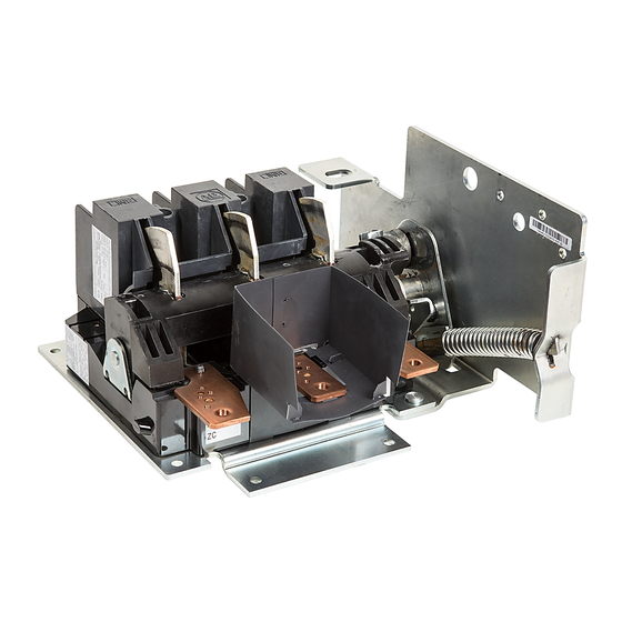
Universal Disconnect Switch Installation Instructions (400A) Rod Operated Switch Installation Switch Installation Overlay template E (400 A) over D . Install disconnect switch. Use template D to locate handle holes on mounting plate. 1 /2 l e s it c le s w it 1 /2... -
Page 3: Connecting Rod Installation
Universal Disconnect Switch Installation Instructions (400A) Connecting Rod Installation First rod connects the handle to the switch Verify that disconnect switch and handle are in "OFF" Rotate rod to adjust. position. (Switch blades will be visible) Adjust to create minimal gap with spring bracket. -
Page 4: Cable Operated Mechanism Installation
Universal Disconnect Switch Installation Instructions (400A) Cable Operated Mechanism Installation IMPORTANT: Verify that the cable assembly does not interfere with any mechanical and moving parts. Keep the cable conduit away from all heat sources and current carrying terminals, fuses, transformers, etc. IMPORTANT: When locating the 400A switch, verify that the minimum diameter for the loop of the cable between the switch mechanism and the handle mechanism is not less than 10 inches. -
Page 5: Cable Operated Switch Installation
Universal Disconnect Switch Installation Instructions (400A) Cable Operated Switch Installation Locate Switch. Use template E Assemble disconnect switch assembly to mounting plate. where desired. 2" 1 /2 11" l e s it c w it 1 /2 t i n 2 "... -
Page 6: Connecting Rod Adjustment Procedure
Universal Disconnect Switch Installation Instructions (400A) Handle Mechanism Installation (Cont'd) Install hitch pin clip. Turn disconnect handle "OFF" and install handle mechanism spring. Hitch Pin Clip ATTENTION: CHECK FOR PROPER OPERATION. Connecting Rod Adjustment Procedure Adjustment Procedure if switch does not turn "ON". Adjustment Procedure if switch does not turn "OFF". -
Page 7: Enclosure Without Handle Cutout
Universal Disconnect Switch Installation Instructions (400A) Enclosure without Handle Cutout • Enclosures with a Flange Thickness less than 3/16" use dimensions below to install disconnect handle. Locate Handle Drill Handle Holes Locate Disconnect Switch 2" 5" 1-1/8" 1-3/8" (2) .328" Dia. Holes 14-3/8"... -
Page 8: Line Terminal Guard Installation
Universal Disconnect Switch Installation Instructions (400A) Line Terminal Guard Installation Assemble and Install Line Terminal Guard Lug Installation Line Terminal Adapter Installation Wire Clamp 175-200 lb-in Adapter 20-23 Nm 175-200 lb-in 20-23 Nm Lug Adapter Kit Wire Catalog Number Torque Range (1) 14-10 STR/SOL (1) 8 STR... -
Page 9: Trailer Fuse Block Installation
Universal Disconnect Switch Installation Instructions (400A) Direct Mount Fuse Installation Trailer Fuse Block Installation 400A Fuses (Class J Only) Trailer Fuse Block Location Cut phase barriers along line. (400A Class H, J, R Fuses) Thread forming screws 4 - 3/4" 400 Amp Trailer Fuse Block (1494U-F400) Torque 175-200 lb-in... -
Page 10: Fuse Clip Installation
Universal Disconnect Switch Installation Instructions (400A) Fuse Clip Installation 400A Fuses (Class H, J, R) 23-37 lb-in 16-22 lb-in 200A Fuse Clips 200A Fuse Clips 2.6-4.2 Nm 1.8-2.5 Nm 40-55 lb-in 22-37 lb-in 400A Fuse Clips 400A Fuse Clips 4.5-6.2 Nm 2.5-4.2 Nm Protective Cover Installation Punch and drill (4) 11/64"... -
Page 11: Bulletin 1494U Disconnect Switch Kit Optional Accessory List
Universal Disconnect Switch Installation Instructions (400A) Bulletin 1494U Disconnect Switch Kit Optional Accessory List Disconnect Switch Kit Catalog Number and Description 1494U-D400 Switch 1494F-M2 (7-1/2" Painted Metal) (400A / 600A) Handle 1494F-S2 (7-1/2" Stainless Steel) (400A / 600A) 1494V-RB3 (Standard) (400A / 600A) Enclosure Working Depth: 9-1/2"... - Page 12 Cover Rockwell Automation maintains current product environmental information on its website at http://www.rockwellautomation.com/rockwellautomation/about-us/sustainability-ethics/product-environmental-compliance.page. Allen-Bradley, Rockwell Software, and Rockwell Automation are trademarks of Rockwell Automation, Inc. Trademarks not belonging to Rockwell Automation are property of their respective companies. EEE Yönetmeliğine Uygundur.
Need help?
Do you have a question about the 1494U-D400 and is the answer not in the manual?
Questions and answers