
Related Manuals for RM Italy BLA600


Summary of Contents for RM Italy BLA600
-
Page 1: User Manual
Solid State HF & 6m 500W Linear Power Amplifier BLA600 User Manual Rev 1.0 June 2017 Costruzioni Elettroniche http://www.rmitaly.com... -
Page 4: Introduction
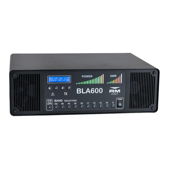
Introduction The RM Italy BLA600 is a fully automatic HF & 6m 500W solid state linear amplifier suitable for seamless integration with all modern trans- ceivers. BLA600 utilises rugged Freescale MRF6VP5600H 50V device for high power and high reliability operation. -
Page 5: Table Of Contents
Contents 1. Front Panel Description............2 2. Rear Panel Description............3 3. Introduction................4 4. Warning................6 5. Unpacking................7 6. Installation................7 7. Antenna Output Selection............ 9 8. Operation................10 9. Modulation Modes............... 13 10. Menu..................13 ............... 14 .............. -
Page 6: Warning
4. Warning! Before connecting this product to the AC supply verify that the model supplied is configured for the correct line voltage be it 115Vac 230Vac or 240Vac. Failure to do this may cause extensive damage to the amplifier. Dangerous voltages are present inside this product, AC Line Voltage 230/240Vac, HV 380Vdc and RF voltages. -
Page 7: Unpacking
As the amplifier is quite heavy make sure that the supporting structure is capable of supporting the weight. Connection: The BLA600 requires the following connections in order to function. The output of the transceiver should be connected to the RTX input on the rear panel with a suitable 50 Ohm patch cable terminated in PL259 UHF connectors. - Page 8 In TX input to the amplifier is 50 ohms. The BLA600 also requires a PTT input from the transceiver to switch between RX and TX. Without this input the amplifier cannot be used. Look in the manual of your transceiver for how to connect to the PTT Output.
-
Page 9: Antenna Output Selection
7. Antenna Output Selection The BLA600 has 3 user configurable antenna outputs. As supplied from the factory the default antenna output is Ant:1 for all bands. Each band may be independently configured to any one of the three outputs. To change any particular band to different antenna output it is necessary to be in ‘Standby’... -
Page 10: Operation
160m and 6m for full output. Due to the accurate frequency reading and high speed band switching of the BLA600 a CAT interface connection is not required for automatic band change. A high speed PIN Diode switch is used so... - Page 11 selected manually prior to transmission, but not essential). Manual band filter selection can only be made when the amplifier is in ‘Standby’ mode. When the Amplifier is switched to ‘OPR’ (Operate) no manual band change can be made, the amplifier will automatically switch bands as soon as the radio begins to transmit after a band change.
- Page 12 It is of course possible to make a final adjustment manually so long as the adjustments are small. The BLA600 is protected against high VSWR loads but it is very bad practice to tune the antenna at high power and there is always the risk of damage to both the amplifier and ATU as well as creating unneccessary interference on the bands.
-
Page 13: Modulation Modes
See menu 5:CW QSK for further details. 10. Menu: To enter into the menu system the BLA600 must be in ‘Standby’ mode. It is not possible to enter the menu when in ‘Operate’ mode. To enter the menu system press the ‘Enter’ key ^ Press the ‘Navigate’... -
Page 14: 1:Alc
10V range, that is suitable for all modern transceivers. If using the ALC menu make sure that the BLA600 ALC Output on the rear panel ^ is connected to the radios ALC input. See your radios instruction manual for further details. - Page 15 Press the ‘Enter’ key ^: Adjustment of Max Power. Adjust the ALC ‘MAX’ trimmer on the rear panel in TX until the transceiver power just starts to reduce. At this point readjust the ‘MAX’ trimmer in the opposite direction to just above the point where the power starts to fall, so that the output power is not affected.
-
Page 16: 2: Temp
2: TEMP Change the display temperature between degrees Fahrenheit and degrees Celsius. Select menu ‘2: Temp’ with the ‘Navigate’ key a, press the ‘Enter’ key ^ to access the menu. An arrow cursor will be shown at the end of the line indicating which is the currently active setting. -
Page 17: 4: Contrast
4: CONTRAST Change the contrast of the LCD display. There are 3 options Low, Medium and High. Select menu ‘4:Contrast’ with the ‘Navigate’ key a. Press ‘Enter’ key ^ to access the menu. You can now use the ‘+’ key ` to increase the contrast and the ‘-‘ key _ to reduce the contrast. -
Page 18: 6: Standby (Stb) Parameters
6: Standby Parameters During RX it is possible to monitor two of the following parameters on the LCD display: Pin T1 (Input Power and T1, (T1- Temperature of Heatsink at transistor) Pin T2 (Input Power and T2, (T2 Temperature of Heatsink at exhaust exit) T2 T1 (T2-Temperature of Heatsink at exhaust and T1-Temperature of Heatsink at the transistor) Use the ‘Navigate’... -
Page 19: 8: Default
Use the ‘Navigate’ key a to select menu ‘7:TX Parameters’. Press the ‘Enter’ key ^ to access the menu and use the ‘+’ ` and ‘-‘ ` keys to choose from the above ten choices. Press the ‘Enter’ key ^ again to save the current selection and return to the menu list. -
Page 20: Protection
11. Protection: The BLA600 has a comprehensive and rapid reacting protection system. The following parameters are continually monitored during operation. RF input frequency, (within limits of operation bandwidth), RF drive level (40W 160m, 25W all other bands). Forward and Reflected voltages, from which the VSWR is calculated, (maximum VSWR 2.5-3:1). -
Page 21: Operational Errors
3 seconds along with an audible alarm (5 short tones). The Alarm indication LED will illuminate and remain on. The BLA600 will continue to function, as all of the other safety measures are still protecting the amplifier, however we recommend that the cause of the problem be investigated before further use. - Page 22 This indicates excessive input power from the Transceiver on the bands from 80 to 10m. The amplifier will sound 5 short error tones and the Alarm LED will illuminate. Reduce the input power and press the STB/OPR key to reset the amplifier. This indicates excessive input power from the Transceiver on the bands 160 and 6m.
-
Page 23: Grounding
12. Grounding: It is beyond the scope of this manual to provide a definitive guide into the controversial subject of RF grounding, as it is a subject all to itself and very much depends on how the equipment is connected and types of antenna used. There are both arguments for and against the stereotypical RF station ground. - Page 24 Radio etc. Another example is using an antenna tuner with a balanced feeder to the antenna. It’s balanced right? Well, maybe not. If the tuner uses a ‘VOLTAGE’ BALUN, (typically a 4:1 Ruthroff mounted in the ATU), and you have a high VSWR on the balanced feeder, much greater than 50 ohms, the voltage BALUN can saturate, and cause all manner of problems with balance, as can the balanced feeder if not properly routed, coupling with close proximity to metallic objects.
-
Page 25: Warranty
13. Warranty. 3 Costruzioni Elettroniche S.n.c. Guarantees that the product is free from manufacturing defects both parts and workmanship for a period of 12 months. The warranty commences on the date of purchase. Any work undertaken for the warranty must be carried out by 3 or an authorised 3 service centre. -
Page 26: Specifications
14. Specifications: Frequency: 1.8-30 MHz & 50-54 MHz LPF’s Optimised for 1.800-2.000 MHz the following Bands: 3.500-4.000 MHz 7.000-7.300 MHz 10.100-10.150 MHz 14.000-14.350 MHz 18.068-18.168 MHz 21.000-21.450 MHz 24.890-24.990 MHz 28.000-29.700 MHz 50.000-54.000 MHz Active Device: NXP / Freescale MRFE6VP5600H (50V) Output Power: 500W+ PEP P1dB Input Power:... - Page 27 PTT Input: Close to ground TX, Open Circuit RX, (Suitable for Open Drain / Collector / Relay switching). Output +5V S/C current <15mA in TX. ALC Output: Negative going voltage, (0 to –10V), Adjustable. Dimensions: 430mm x 142mm x 324mm (Width x Height x Depth) Weight: 21.5 kg...
Need help?
Do you have a question about the BLA600 and is the answer not in the manual?
Questions and answers