Advertisement
Table of Contents
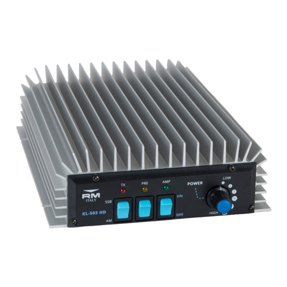
KL503 HD
HF 25—30 MHz Linear Amplifier
Specifications:
Operation Frequency:
Modulation Types:
Transistor:
Max I/P Current:
Power Supply:
Input Fuse (Internal):
Input RF Power:
Output RF Power:
Maximum bypass power (Amplifier off): 50W max
Input VSWR:
Output VSWR Maximum:
Harmonic Output:
WARNING:
Before using this product please read carefully all of
the information in this manual or at least the quick start guide!!! To avoid dam-
age or incorrect operation this is extremely important!!!
Ver 1.0 May 2018
25—30 MHz (10m Amateur HF Band)
SSB,CW,AM, FM, data etc (All narrowband modes)
8x RM 3 MOSFET + 1x RM 4 MOSFET Driver
30A
13VDC+/- 1V 40A
3x10A (5x20mm Fast)
1-35W max (All modes)
300W max
1.1—1.5:1
2.5:1
>-50dBc 25-30MHz
Quick Start Guide:
A more complete guide to the installation is featured later
1.
Connect the RTX input connector to transceiver with
50 Ohm patch cable
2.
Connect the ANT Output of the Amplifier to SWR
Bridge / Wattmeter (If required), and then the Antenna
(50 Ohm load Impedance)
3.
Connect the Amplifier DC power Cable to a suitable
13VDC (± 1V) Power Supply or Auto Battery. Pay at-
tention to the correct polarity
4.
Make sure that the amplifier is switched off
5.
Adjust the Transceivers RF output power to 25W
(35W max) if it is capable of more than 25W output
6.
Switch on the Amplifier and start operating
7.
Check that the antenna VSWR is acceptable with the
amplifier in use. Any large increase in VSWR indi-
cates that the Antenna is not suitable for the power
being used. Operation should be halted immediately
to avoid damage to the Amplifier / Radio / ATU etc.
2
Advertisement
Table of Contents

Related Manuals for RM Italy KL503 HD


Summary of Contents for RM Italy KL503 HD
- Page 1 KL503 HD Quick Start Guide: HF 25—30 MHz Linear Amplifier A more complete guide to the installation is featured later Connect the RTX input connector to transceiver with 50 Ohm patch cable Connect the ANT Output of the Amplifier to SWR...
-
Page 2: Front / Rear Panel Description
Installation: Front / Rear Panel Description Unpack the amplifier from it’s shipping carton and inspect for any signs of damage. The ampli- fier should be installed (either fixed or mobile installation), in a place that allows good ventila- tion and provides a suitable base to support it. Failure to allow for reasonable ventilation will Front Panel cause the amplifier to overheat and shutdown prematurely. -
Page 3: Operation
35W is the maximum permissible input power to The KL503 HD is fitted with an RX preamp, that when activated can help to increase the re- the amplifier, but approximately 25W input should be sufficient to realise full output, and an ceived signal level. - Page 4 The amplifier should give full output with approximately 25W input. Excessive input power should be avoided and the amplifier should always be operated in a responsible manner. The KL503 HD features an input attenuator that may be used to reduce the output of the am- plifier if the drive radio does not have the facility to reduce its output power.
- Page 5 Typical Harmonic Output Att1 7dB Schematic Diagram KL503...
-
Page 6: Warranty
Attention: The use of Linear Amplifiers are controlled by specific laws within the country of use. These laws must be known to the user and are entirely the responsibility of the user. The manufacturer declines any responsibility from unlawful use. Warranty: This product is covered by a 24 month warranty commencing from the date of purchase.
Need help?
Do you have a question about the KL503 HD and is the answer not in the manual?
Questions and answers