Advertisement
Quick Links
Remote Control:
The remote head is not supplied from RM Italy however the circuit diagram below shows the requirements
of creating a remote front panel if required. The connector is an RJ45 type and cable length should be no
more than 3m in length. The remote front panel controls offer the same functionality as the front panel of
the KL506.
The function of the pins present on the remote connector as as follows:
1.
Ground
2.
Preamplifier ON input
3.
Wattmeter signal output
4.
Power output for the remote command
5.
Hi power input
6.
Linear amplifier ON input
7.
Low power input
8.
SSB input
At no time should should voltage appear on pins 5 & 7 at the same time.
When using the remote control, the switches on the front panel should be set as follows:
Preamplifier OFF
Linear Amplifier OFF
SSB / AM - AM Mode
Power set to Mid, (center), position.
The digram below shows the circuit diagram of the remote control circuit and pin out of the RJ46 front
Warranty:
The KL506 is covered by a 24 month warranty against manuafacturing defects, from the
date of purchase. The RF transistors, external and asthetic damage are not included in the
warranty.
www.rmitaly.com info@rmitaly.com
Pin1
Pin 8
KL506
HF 10m Linear Amplifier
Specifications:
Operation Frequency:
Modulation Types:
Transistor:
Max I/P Current:
Power Supply:
Input Fuse (Internal):
Input RF Power:
Output RF Power:
Maximum bypass power (Amplifier off): 50W max
Input VSWR:
Output VSWR Maximum:
Harmonic Output:
WARNING:
Before using this product please read carefully all of
the information in this manual or at least the quick start guide!!! To avoid
damage or incorrect operation this is extremely important!!!
Ver 1.0 Oct. 2020
10m Amateur Band, (1.8-30MHz with LPF)
SSB,CW,AM, FM, (All narrowband modes)
4x RM SD1446 Transistor
35A
13.8VDC+/- 1V 50A
3x12A (5x20mm Fast Blow Glass Fuse)
1-10W max (All modes)
230W max CW/FM
1.1—1.5:1
2.5:1
>-50dBc 25-30MHz
Advertisement

Subscribe to Our Youtube Channel
Related Manuals for RM Italy KL506


Summary of Contents for RM Italy KL506
- Page 1 Remote Control: KL506 The remote head is not supplied from RM Italy however the circuit diagram below shows the requirements of creating a remote front panel if required. The connector is an RJ45 type and cable length should be no more than 3m in length.
- Page 2 Any large increase in VSWR indi- cates that the Antenna is not suitable for the power being used. Operation should be halted immediately to avoid damage to the Amplifier / Radio / ATU etc. Schematic Diagram KL506...
-
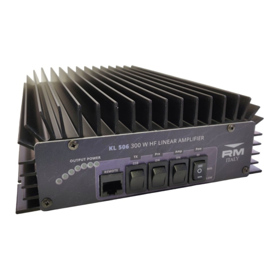
Page 3: Front / Rear Panel Description
Front / Rear Panel Description Front Panel Output Power Level display Amplifier ON LED Remote Control port Preamplifier ON LED SSB Delay switch TX LED RX Preamplifier ON /OFF Switch Amplifier ON / OFF switch Input Power Attenuator Output Power Level LED indicator Green Low Power Orange... - Page 4 Installation: KL506 Broadband use: Unpack the amplifier from it’s shipping carton and inspect for any signs of damage. The ampli- The KL505 is designed for operation on the 10m Amateur radio band, from fier should be installed (either fixed or mobile installation), in a place that allows good ventila- 28.000MHz to 29.700MHz however the amplifer has useful gain covering all of...
- Page 5 (if used). This is very important safety requirement for any radio transmission equipment but as power increases becomes increasingly important. A good RF ground will also Typical Output Power KL506 10m help to prevent any returned RF from causing problems with the equipment. Usually erratic (28.850MHz)
- Page 6 Running the amplifier a little under max output will also allow the amplifier to run cooler and make it more reliable for many years of use. The KL506 may be used for all of the common narrow band transmission modes such as SSB, CW,AM,FM, SSTV and data modes etc.
Need help?
Do you have a question about the KL506 and is the answer not in the manual?
Questions and answers