Advertisement
Quick Links
Specifications:
Operation Frequency:
Modulation Types:
Transistor:
Max I/P Current:
Power Supply:
Input Fuse (Internal):
Input RF Power:
Output RF Power:
Maximum bypass power (Amplifier off): 50W max
Input VSWR:
Output VSWR Maximum:
WARNING:
all of the information in this manual or at least the quick start guide!!! To
avoid damage or incorrect operation this is extremely important!!!
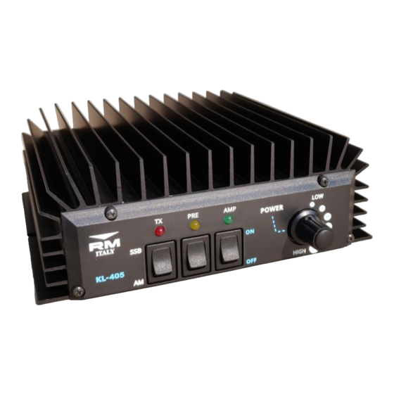
KL405
HF 10m Linear Amplifier
Before using this product please read carefully
10m Amateur Band, (1.8-30MHz with LPF)
SSB,CW,AM, FM, (All narrowband modes)
2x RM SD1446 Transistor
22A
13.8VDC+/- 1V 30A
3x12A (5x20mm Fast Blow Glass Fuse)
1-10W max (All modes)
180W max
1.1—1.5:1
2.5:1
Ver 1.0 Jul. 2020
Advertisement

Related Manuals for RM Italy KL405


Summary of Contents for RM Italy KL405
- Page 1 KL405 HF 10m Linear Amplifier Ver 1.0 Jul. 2020 Specifications: Operation Frequency: 10m Amateur Band, (1.8-30MHz with LPF) Modulation Types: SSB,CW,AM, FM, (All narrowband modes) Transistor: 2x RM SD1446 Transistor Max I/P Current: Power Supply: 13.8VDC+/- 1V 30A Input Fuse (Internal):...
- Page 2 Quick Start Guide: A more complete guide to the installation is featured later Connect the RTX input connector to transceiver with 50 Ohm patch cable Connect the ANT Output of the Amplifier to SWR Bridge / Wattmeter (If required), and then the An- tenna (50 Ohm load Impedance) Connect the Amplifier DC power Cable to a suit- able 13.8VDC (±...
-
Page 3: Front / Rear Panel Description
Front / Rear Panel Description Front Panel Receive Pre-Amplifier ON / OFF Switch Amplifier ON / OFF Switch Input Attenuator 6 position, (For output power adjustment). AM / SSB Switch Pre Amplifier ON LED Amplifier ON LED TX indicator LED Rear Panel RTX SO239 RF input connector DC Input power connector. - Page 4 Installation: Unpack the amplifier from it’s shipping carton and inspect for any signs of damage. The amplifier should be installed (either fixed or mobile installation), in a place that allows good ventilation and provides a suitable base to support it. Failure to allow for reasonable ventilation will cause the amplifier to overheat and damage may occur.
- Page 5 The installation location must also provide a suitable ground system both for RF and the AC power supply, (if used). This is very important safety requirement for any radio trans- mission equipment but as power increases becomes increasingly important. A good RF ground will also help to prevent any returned RF from causing problems with the equip- ment.
- Page 6 Mode: The KL405 may be used for all of the common narrow band transmission modes such as SSB, CW,AM,FM, SSTV and data modes etc. RX Preamplifier: The KL405 is fitted with an RX preamplifier, that when activated can help to increase the received signal level.
- Page 7 The KL405 features an input attenuator that may be used to reduce the output of the amplifier if the drive radio does not have the facility to reduce its output power.
- Page 9 KL405 Broadband use: The KL405 is designed for operation on the 10m Amateur radio band, from 28.000MHz to 29.700MHz however the amplifer has useful gain covering all of the bands from 160m to 10m, (See the diagram ‘Gain vs Frequency’ on the previous page). The amplifier does not feature Low...
- Page 10 KL405 Schematic Diagram...
- Page 12 Attention: The use of Linear Amplifiers are controlled by specific laws within the country of use. These laws must be known to the user and are entirely the responsibility of the user. The manufacturer declines any responsibility from unlawful use. Warranty: This product is covered by a 24 month warranty commencing from the date of purchase.
Need help?
Do you have a question about the KL405 and is the answer not in the manual?
Questions and answers