
Related Manuals for RM Italy BLA 350


Summary of Contents for RM Italy BLA 350
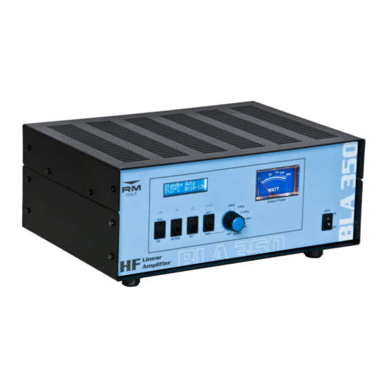
- Page 1 Amplificatore Lineare per bande HF a stato solido Solid-State HF Linear Power Amplifier BLA 350 Manuale Utente User Manual Costruzioni Elettroniche S.n.c. http://www.rmitaly.com...
- Page 2 Un uso attento e corretto vi farà apprezzare le "performance" del BLA 350 per molti anni senza nessun intervento tecnico.
-
Page 3: Table Of Contents
2. Indice – Index Introduzione – Introduction ..........................2 Indice – Index ..............................3 Specifiche, precauzioni - Specifications, Caution .................... 5 Descrizione parte Anteriore - Front panel description ..................6 Descrizione parte Posteriore - Rear panel description ..................7 Italiano ................................7 6.1 Rimozione dall'imballo ed ispezione ......................7 6.2 Procedura d'installazione ..........................7 6.3 Connessione alla rete ..........................7... - Page 4 English Precaution ...........................12 16.1 Removal from packaging and inspection ....................12 16.2 Installation ...........................12 16.3 Connection to AC supply.........................12 16.4 Antenna ...........................12 16.5 GROUND ...........................12 16.6 WARNING ...........................12 OPERATION ...........................12 17.1 CW Operation ...........................12 17.2 Initial Settings ...........................12 17.3 Standby ...........................13 17.3.1 MENU ...........................13 17.3.1.1 ALC Setting......................13 17.3.1.1.1 Adjust ALC ....................13...
- Page 5 3. SPECIFICHE – SPECIFICATIONS Frequenza - Frequency : 1.5 ~ 30 MHz all amateur bands including WARC bands Modi - Mode: AM, FM, SSB, CW, RTTY Potenza di pilotaggio - RF Drive: 12W typ. (14W max.) Potenza d'uscita Media – Average Output Power: 300W CW (typ.) ±1dB Guadagno –...
-
Page 6: Descrizione Parte Anteriore - Front Panel Description
Descrizione parte anteriore – Front panel description Italiano 6.1 Rimozione dall'imballo e Ispezione Rimuovere, con molta attenzione, il BLA 350 dal proprio Precauzioni imballo, controllare che il lineare non abbia nessun segno Display LCD LCD Display Visualizza i parametri di funzionamento... -
Page 7: Descrizione Parte Posteriore - Rear Panel Description
Descrizione connessioni e dati di targa Connections and technical data visibile di danni. possibile attivare da menù un circuito VOX interno al BLA 350 Agire delicatamente su ogni controllo per verificare che abbiano che fornisce il segnale necessario, per un miglior controllo della un normale funzionamento. -
Page 8: Antenna
Posizionare i comandi del BLA 350 nel seguente modo (fare riferimento al paragrafo 4): 6.4 ANTENNA MAIN ON/OFF ......OFF Il BLA 350 è costruito per l'uso con antenne che presentano un Standby/ON .........OFF carico resistivo di 50 sulla frequenza di lavoro, in caso di uso LPF ...........indifferente AUTO/MANUAL ......AUTO... -
Page 9: Int. Vox
7.3.1.4 SSB Delay 7.4 OPERATE Commutando l'interruttore Standby/ON (\) su ON si entra in modalità Operate ed il BLA 350 si prepara ad esprimere tutta la sua potenza. 7.4.1 Default setting In questo menù è possibile variare le impostazioni della Per avere un uso immediato dell'amplificatore è... -
Page 10: Comandi
Il display visualizzerà: potenza. 8.1 OVER Input Power Se la potenza di ingresso all'amplificatore supera i 13W lampeggia l'indicazione rossa dell'indicatore WARNING (e) e sul display viene scritto Power TRX >13W. Nella prima riga è visualizzato lo stato dell'amplificatore e l'impostazione della gestione filtri. - Page 11 anomalie, in questo caso se il rapporto di onde proprio insindacabile giudizio se effettuare al riparazione presso supera 3,0:1 il funzionamento potrebbe uscire dai la propria sede. Le spese di spedizione da e verso il laboratorio limiti di sicurezza, viene emesso un segnale audio, si rimarranno a carico del cliente.
-
Page 12: Removal From Packaging And Inspection
Chapter 5. The ALC output from the transceiver connects to connecting cables and if necessary return to a authorised the ALC input (^) of the BLA 350 (refer to Chapter 17.3.1.1 for service centre for testing. Do not subject the amplifier to... -
Page 13: Alc Setting
Power/ON Standby/ON Any Position AUTO/MANUAL AUTO 17.3 Standby This menu allows the unit of temperature to be changed on the display. Switch the POWER switch to ON ( par.4), The LCD display 17.3.1.2.1 Celsius will illuminate([) , the analogue panel meter will illuminate (b). Selection of temperature in European units. -
Page 14: Monitoring The Amplifier Operation
17.3.1.6 Dimmer mode. 17.4.3 Controls The front panel features several user controls. These should only be operated when the amplifier is not in transmission. 17.4.3.1 Stby/ON (\) Switches the amplifier between Standby (Stby) and It is possible to adjust the brightness of the LCD back Operate (ON) modes. - Page 15 Any work to protect the amplifier from excessive dissipation in this case. undertaken for the warranty must be carried out by RM Italy or The amplifier operates at it’s best when the VSWR is below an authorised RM Italy service centre.
- Page 16 Menu' ALC Setup Now adjust ALC Level then OK Temp Celsius ¬ Fahrenheit Int VOX Disabled ¬ Enabled SSB Delay 0 ms 100 ms 250 ms 500 ms ¬ 750 ms 1000 ms Fan Speed Quiet mode ON – OFF Max Speed Man.
- Page 17 -17-...
- Page 18 -18-...
- Page 19 -19-...
-
Page 20: Repair Form
BLA 350 REPAIR FORM BLA 350 Model Serial number …........ date …....Amplifier settings at the moment of Fault Transceiver …........…....................... Antenna …........…....................... PTT connection? ALC connection? Was the power output of the transceiver set to the maximum level? If not set to maximum power, what is the maximum value? …....…...........
Need help?
Do you have a question about the BLA 350 and is the answer not in the manual?
Questions and answers
My MLA 350 seems to lock up and not transmit when the drive is applied. There is no warning message, and the power level never exceeded nine watts of drive.